Important Diagrams: Electricity | Science Class 10 PDF Download
| Table of contents |
|
| Important symbols related to electric circuits |
|
| Electric Circuit |
|
| Representation of series and parallel connections |
|
| Ohm's law (V=IR) |
|

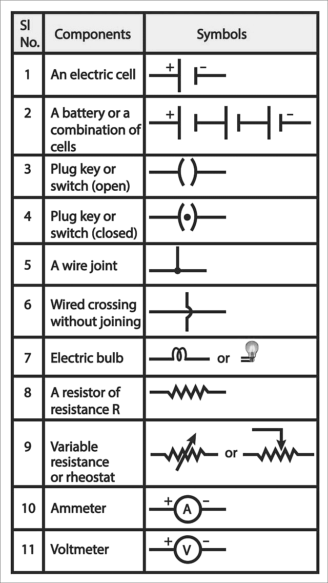
Important symbols related to electric circuits
In electric circuits, several important symbols represent components:
- Battery: A pair of long and short parallel lines (positive and negative terminals).
- Resistor: A zigzag line.
- Capacitor: Two parallel lines with a small gap between them.
- Switch: A break in a line with an open or closed gap.
- Bulb: A circle with a cross inside.
- Wire: A straight line.
- Ammeter: A circle with an "A" inside, measuring current.
- Voltmeter: A circle with a "V" inside, measuring voltage.
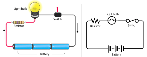
Electric Circuit
A system of conducting elements that are designed to conduct electric current for a particular purpose is known as an electric circuit. An electric circuit consists of a source of electrical energy; elements that either transform, dissipate, or store this energy; connecting wires. To prevent power overload, circuits often include a fuse or circuit breakers.
 Electric Circuit
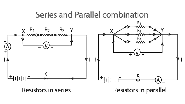
Representation of series and parallel connections
In a series connection, components are connected end-to-end, and the current flows through each one in a single path. If one component fails, the whole circuit is broken. In a parallel connection, components are connected across the same two points, creating multiple paths for current. If one component fails, others continue to work. Series circuits share the same current, while parallel circuits share the same voltage across each component.
Ohm's law (V=IR)
Ohm's Law states that the current flowing through a conductor is directly proportional to the voltage across it and inversely proportional to its resistance. It is mathematically represented as: V=I×R
Where:
- V is the voltage (in volts),
- I is the current (in amperes),
- R is the resistance (in ohms).
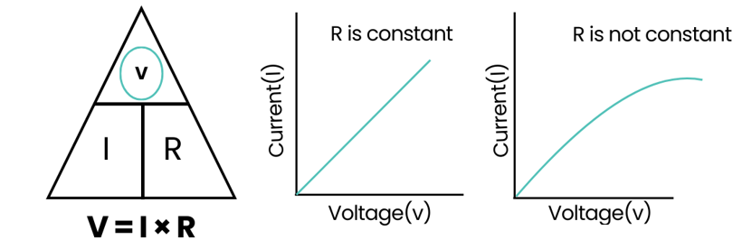 Graphical Representation
|
80 videos|569 docs|80 tests
|
FAQs on Important Diagrams: Electricity - Science Class 10
| 1. What are the basic symbols used in electric circuit diagrams? |  |
| 2. How do you represent series and parallel connections in electric circuits? | |
| 3. What is Ohm's Law and how is it applied in electric circuits? | |
| 4. Can you explain the significance of Ohm's Law in real-world electrical applications? | |
| 5. What are common mistakes to avoid when working with electric circuit diagrams? | |


Important Diagrams: Electricity | Science Class 10
,Exam
,Sample Paper
,Important questions
,practice quizzes
,Semester Notes
,Summary
,Objective type Questions
,MCQs
,shortcuts and tricks
,Free
,Viva Questions
,video lectures
,Important Diagrams: Electricity | Science Class 10
,ppt
,Extra Questions
,past year papers
,study material
,mock tests for examination
,Important Diagrams: Electricity | Science Class 10
,Previous Year Questions with Solutions
;


Important Diagrams: Electricity Free PDF Download
Importance of Important Diagrams: Electricity
Important Diagrams: Electricity Notes
Important Diagrams: Electricity Class 10 Questions
Study Important Diagrams: Electricity on the App
|
© EduRev
|
Education Revolution
|


|


