Introduction on Synchronous Machines


A synchronous machine is an alternating-current rotating machine whose speed under steady-state conditions is directly determined by the supply frequency and is therefore proportional to the frequency of the current in its armature.
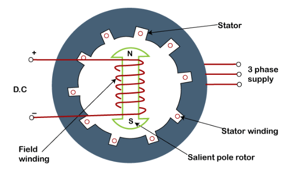 Diagram of Synchronous Machine
- The magnetic field produced by the stator currents rotates at the synchronous speed, and the magnetic field produced by the rotor field current also rotates at the synchronous speed; a steady torque results when the two fields remain locked in space. For this reason such machines are called synchronous machines - they operate at constant speed determined by the supply frequency under steady state conditions.
- Polyphase synchronous generators (alternators) are the most common large machines used to produce electric power in power systems, e.g., steam-turbine and hydroelectric units used in the grid.
- Because the rotor runs at the synchronous speed of the stator field, synchronous motors are used where a constant-speed drive is required; variable speed can be obtained using a suitable frequency changer (for example, an inverter).
- The reactive power exchange of a synchronous machine can be controlled by changing the magnitude of the rotor field current. Unloaded synchronous machines used chiefly for reactive power control and power-factor correction are known as synchronous condensers; in large sizes they are often more economical than static equipment.
- Synchronous machines can operate both as generators and as motors. Several synchronous generators commonly operate in parallel at a power station and share the load. A generator carrying little or no active load may be left running (floating) on the system as an unloaded synchronous machine rather than being shut down.
- Modern large synchronous generators commonly have ratings of several hundred MVA; machines of still larger ratings are used in major power stations.
Try yourself: What are large polyphase synchronous generators called?
Construction of Synchronous Machines
The typical synchronous machine has a three-phase armature winding on the stator and a direct-current (d.c.) field winding on the rotor.
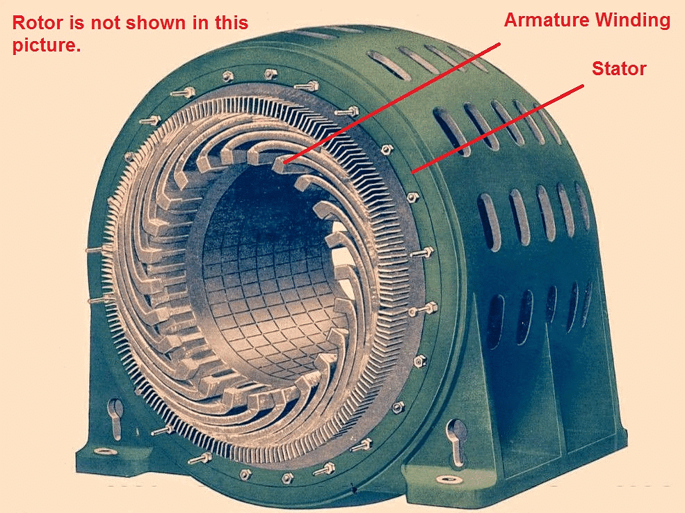
Stator
- The stator is the stationary part of the machine and is assembled from sheet-steel laminations with slots on the inner periphery to accommodate the armature conductors.
- A three-phase armature (stator) winding is placed in these slots. The armature winding on alternators is normally connected in star (Y) form and the neutral is usually grounded for safety and system protection.
- The stator is designed to carry large alternating currents; insulation, cooling passages and mechanical support are provided to suit the machine rating.
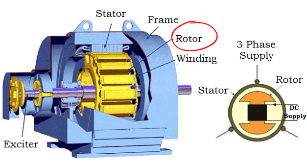
Rotor
The rotor carries the field winding. The field winding is supplied from a d.c. source through slip rings and brushes (or via brushless/rotating rectifiers) so that a steady rotor flux is produced.
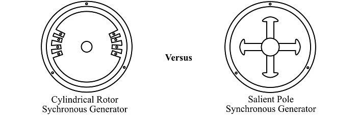
Rotor construction is of two principal types:
- Salient (projecting) pole type
- Non-salient (cylindrical or turbo) pole type
Try yourself: Rotor is the stationary part of the machine and is made up of permanent magnets.
Salient Pole Type
In the salient pole rotor, individual projecting poles are bolted or otherwise fixed to a large circular steel frame that is mounted on the shaft.
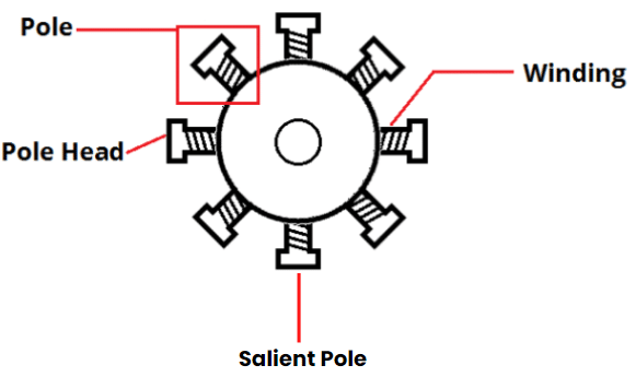 Salient Pole Rotor
- Each pole carries a field winding and the pole windings are connected so that adjacent poles have opposite polarity when the field current flows.
- Salient pole rotors are used in low-speed machines (typically 120-400 r.p.m.), for example in hydroelectric generators driven by water turbines.
- Reasons for using salient-pole construction at low speeds:
- Large pole projections provide the required pole arc and magnetic flux for low-speed machines where many poles are needed to obtain a given frequency.
- Salient pole rotors have large diameters and short axial lengths, which is suitable where a large number of poles is required and mechanical stresses at low speeds are manageable.
- Limitations:
- At high speeds projecting poles cause excessive windage losses and noise.
- Salient pole assemblies are mechanically less robust at high speeds and cannot sustain the centrifugal forces of high-speed operation.
Non-Salient Pole (Cylindrical) Type
In the non-salient (cylindrical) construction, the rotor is a smooth forged steel cylinder with slots in which the field windings are embedded. The pole regions are not visibly projecting from the rotor surface.
- Thefield coils are placed in slots in the rotor surface and are connected to the d.c. supply via slip rings (or through a brushless exciter arrangement).
- The flux distribution around the air gap is nearly sinusoidal, producing a good e.m.f. waveform in the stator.
- Non-salient rotors are used for high-speed turboalternators (driven by steam turbines) operating typically at 1500 r.p.m. (4-pole) or 3000 r.p.m. (2-pole) for a 50 Hz system. For 50 Hz the highest synchronous speed is 3000 r.p.m. (2 poles), the next is 1500 r.p.m. (4 poles).
- Turboalternators generally have small diameter and long axial length and carry fewer poles (commonly 2 or 4 poles).
Classification According to Form of Excitation
1. Brush (Slip-Ring) Excitation Systems
- The rotor field winding requires d.c. excitation, which is commonly supplied by an exciter mounted on the same shaft as the main machine. The exciter may be a small self-contained d.c. generator.
- The d.c. output of the exciter is conducted to the rotor field via two slip rings and brushes.
- In some large, slow-speed machines the main exciter may be driven and controlled by a pilot exciter (which may be self-excited or a permanent magnet machine) to ensure reliable excitation control.
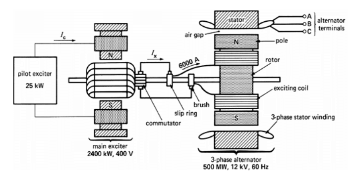 Brushes excitation system for a Synchronous Machine
2. Brushless Excitation Systems
Brushless excitation eliminates brushes and slip rings by using a rotating rectifier assembly. An ac rotating exciter produces an ac voltage which is rectified by the shaft-mounted rectifiers and fed directly to the rotor field.
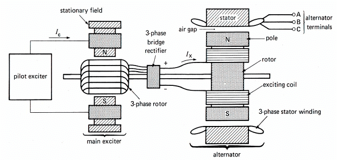 Brushless excitation system for a Synchronous Machine
3. Static Excitation Systems
- Static systems use stationary power electronics (transformers, rectifiers, reactors) to supply d.c. to the field winding. They are common in small alternators and in systems where rapid control of the field is required.
- An external d.c. source or an initial excitation from the system is necessary to start static excitation.
Advantages of Stationary Armature
The standard arrangement places the three-phase armature on the stationary stator and the d.c. field on the rotor. The main advantages are:
- (i) Stationary windings are much easier to insulate for high voltages because they are not subject to centrifugal stress.
- (ii) The stationary armature can be connected directly to external high-voltage transmission lines without the need for large, unreliable slip rings and brushes.
- (iii) Only two slip rings and brushes are required to feed the rotor field current; because the field current is relatively small, these slip rings and brushes are light and reliable.
- (iv) The rotor can be made mechanically simple and robust, allowing higher peripheral speeds and greater power output for a given size.
Cooling
- Synchronous machines, particularly large ones, carry very large currents (a well-designed armature current density may be of the order of 10 A/mm2), and the magnetic core is often heavily loaded and partially saturated in places.
- Electrical and magnetic loadings generate heat that must be removed efficiently to avoid damage and to maintain performance.
- The method of cooling influences machine design and may include forced air, water cooling, or gaseous coolants such as hydrogen and helium in very large machines.
Damper Bars
- In addition to the two principal windings (the three-phase armature and the d.c. field), many synchronous rotors include damper bars (also called amortisseur windings) embedded in the pole faces or in the rotor surface.
- Damper bars form a cage similar to the squirrel-cage of an induction motor.
- When the rotor speed departs from synchronous speed (for example during transients), currents induced in the damper bars produce damping torque that opposes oscillations and helps restore synchronism.
- Damper bars also provide a means of starting for synchronous motors: during starting they act as an induction rotor, producing torque until the machine approaches synchronous speed, when the field is energised to pull the rotor into synchronism.
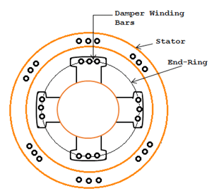 Salient Pole Rotor showing the field winding and damper bars
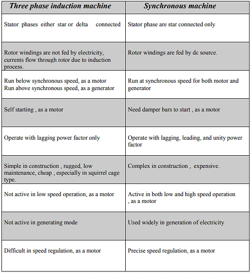
Differences between Three-Phase Induction Machines and Synchronous Machines
Key Relations and Operating Principles
- Synchronous speed Ns (in r.p.m.) for a given supply frequency f (Hz) and number of poles P:Ns = (120 × f) / P
This shows that for a fixed frequency the rotor speed is fixed by the number of poles.
- Induced emf per phase in a sinusoidally distributed winding can be written in basic form as:E = 4.44 × f × Φm × N
where Φm is the maximum flux per pole and N is number of turns per phase. This is a standard form for sinusoidal machines (alternators).
- Power-angle (synchronising) relation (simplified, lossless model):P = (3 × Vt × E) / Xs × sin δ
where Vt is terminal phase voltage, E is internal induced phase emf, Xs is synchronous reactance, and δ is the torque (power) angle between internal emf E and terminal voltage Vt. This relation explains how the developed power depends on the angle δ and on excitation.
- Armature reaction: flux produced by armature currents distorts and/or weakens the main field in the air gap; its effect depends on load power factor and on field excitation.
Starting Methods of Synchronous Motors (brief)
- Use of damper bars (induction starting): the rotor starts as an induction motor and is brought near synchronous speed; the d.c. field is then switched on (or synchronised) to pull the rotor into synchronism.
- Use of an auxiliary (pony) motor to accelerate the machine to near-synchronous speed before excitation.
- Use of a frequency changer or variable frequency drive (inverter) to accelerate and synchronise the rotor at the required speed.
- Use of forced synchronisation procedures (e.g., controlled field application) in conjunction with speed control to achieve safe locking into synchronism.
Applications
- Large synchronous generators in power stations for bulk electric power generation (steam, gas and hydro turbine driven alternators).
- Synchronous motors for constant-speed industrial drives where precise speed regulation is required (pumps, compressors, fans at fixed speed).
- Synchronous condensers (over-excited synchronous motors running unloaded) for reactive power control and power-factor improvement in transmission and distribution systems.
- Voltage regulation and system stability support in large power systems through excitation control and synchronous reactance management.
Frequently Asked Questions (FAQs)
Q.1. What is synchronous condenser?
An over-excited synchronous motor operating on no load, used for the improvement of power factor, is called a synchronous condenser because, like a capacitor, it supplies leading reactive current to the system.
Q.2. State the characteristic features of synchronous motor.
- The motor is not inherently self-starting (unless a starting device or damper bars are provided).
- The speed of operation is always synchronised with the supply frequency irrespective of load (provided synchronism is maintained).
- The motor can operate at any power factor - leading, lagging or unity - by adjusting the field excitation.
Q.3. In what way synchronous motor is different from other motors?
- All electric motors produce torque by interaction of magnetic fields; however, a synchronous motor obtains torque through magnetic locking between the rotating stator field and the steady d.c. field on the rotor.
- The rotor of a synchronous motor runs at an exact synchronous speed determined by supply frequency and number of poles, whereas induction motor speed varies slightly with load (slip).
Q.4. Why a synchronous motor is a constant speed motor?
A synchronous motor operates by magnetic locking between the rotor field and the rotating stator field. The speed of the rotating stator field is directly proportional to the supply frequency, so when the rotor is pulled into synchronism it runs at this fixed synchronous speed.
Q.5. How can the synchronous motor be used as a synchronous condenser?
A synchronous motor is run with over-excitation so that it draws a leading reactive current from the supply. This leading reactive power compensates the lagging reactive demand of other loads, improving the overall power factor of the system. In this role the machine functions similarly to a capacitor bank and is called a synchronous condenser.
FAQs on Introduction on Synchronous Machines
| 1. What is the construction of synchronous machines? |  |
| 2. How are synchronous machines classified according to the form of excitation? | |
| 3. What are the advantages of a stationary armature in synchronous machines? | |
| 4. How does the excitation of synchronous machines affect their operation? | |
| 5. What are the main differences between separately excited and self-excited synchronous machines? | |


 | Explore Courses for Electrical Engineering (EE) exam |
 | Get EduRev Notes directly in your Google search |