Active Elements: Network Theory | Network Theory (Electric Circuits) - Electrical Engineering (EE) PDF Download
When a network element or circuit element has the ability to deliver electrical energy or to produce power gain in the circuit, then the element is called an active element.
In other words, a circuit element for which the slope of its characteristics curve at any point is negative then the element is called an active element.
Active Elements are the network elements that deliver power to other elements present in an electric circuit. So, active elements are also called as sources of voltage or current type.
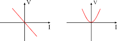
Types of Sources:
We can classify these sources into the following two categories:
- Independent Sources
- Dependent Sources
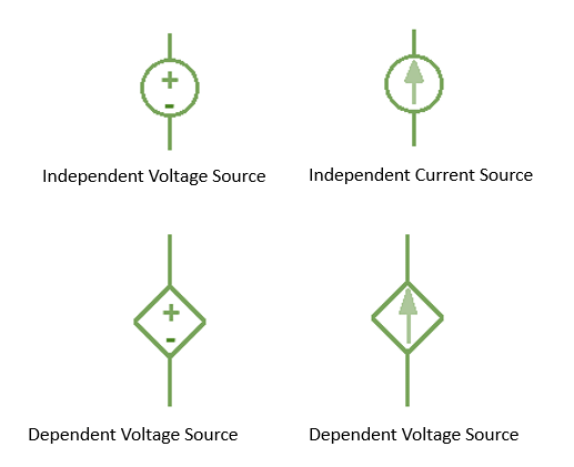
Independent Sources
Independent Sources
As the name suggests, independent sources produce fixed values of voltage or current and these are not dependent on any other parameter.
Independent sources can be further divided into the following two categories:
- Independent Voltage Sources
- Independent Current Sources
(a) Independent Voltage Sources
- An independent voltage source produces a constant voltage across its two terminals. This voltage is independent of the amount of current that is flowing through the two terminals of voltage source.
Independent ideal voltage source and its V-I characteristics are shown in the following figure.
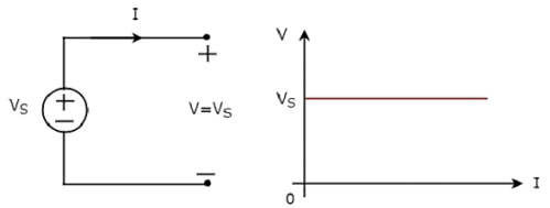
- The V-I characteristics of an independent ideal voltage source is a constant line, which is always equal to the source voltage (VS) irrespective of the current value (I). So, the internal resistance of an independent ideal voltage source is zero Ohms.
- Hence, the independent ideal voltage sources do not exist practically, because there will be some internal resistance.
Independent practical voltage source and its V-I characteristics are shown in the following figure.
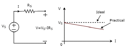
- There is a deviation in the V-I characteristics of an independent practical voltage source from the V-I characteristics of an independent ideal voltage source. This is due to the voltage drop across the internal resistance (RS) of an independent practical voltage source.
(b) Independent Current Sources
- An independent current source produces a constant current. This current is independent of the voltage across its two terminals.
Independent ideal current source and its V-I characteristics are shown in the following figure.
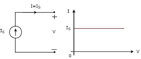
- The V-I characteristics of an independent ideal current source is a constant line, which is always equal to the source current (IS) irrespective of the voltage value (V). So, the internal resistance of an independent ideal current source is infinite ohms.
- Hence, the independent ideal current sources do not exist practically, because there will be some internal resistance.
Independent practical current source and its V-I characteristics are shown in the following figure.
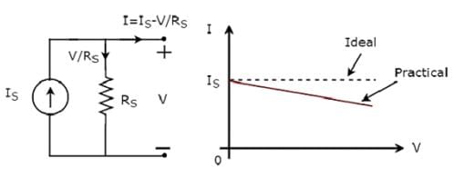 There is a deviation in the V-I characteristics of an independent practical current source from the V-I characteristics of an independent ideal current source. This is due to the amount of current flows through the internal shunt resistance (RS) of an independent practical current source.
Dependent Sources
As the name suggests, dependent sources produce the amount of voltage or current that is dependent on some other voltage or current. Dependent sources are also called as controlled sources. Dependent sources can be further divided into the following two categories:- Dependent Voltage Sources
- Dependent Current Sources
(a) Dependent Voltage Sources
A dependent voltage source produces a voltage across its two terminals. The amount of this voltage is dependent on some other voltage or current.
Hence, dependent voltage sources can be further classified into the following two categories:
- Voltage Dependent Voltage Source (VDVS)
- Current Dependent Voltage Source (CDVS)
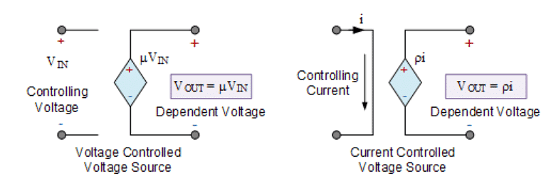
Dependent voltage sources are represented with the signs ‘+’ and ‘-’ inside a diamond shape. The magnitude of the voltage source can be represented outside the diamond shape.
(b) Dependent Current Sources
A dependent current source produces a current. The amount of this current is dependent on some other voltage or current. Hence, dependent current sources can be further classified into the following two categories:
- Voltage Dependent Current Source (VDCS)
- Current Dependent Current Source (CDCS)
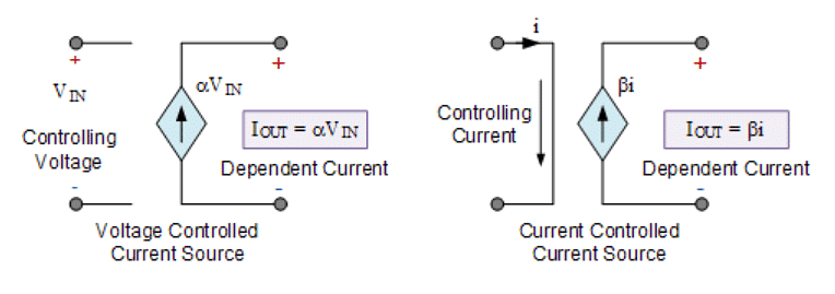
Dependent current sources are represented with an arrow inside a diamond shape. The magnitude of the current source can be represented outside the diamond shape.
We can observe these dependent or controlled sources in equivalent models of transistors.
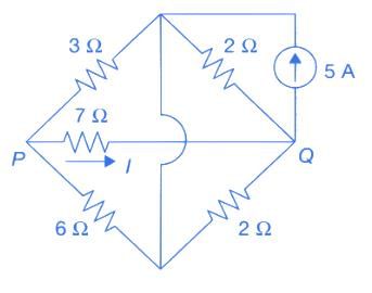
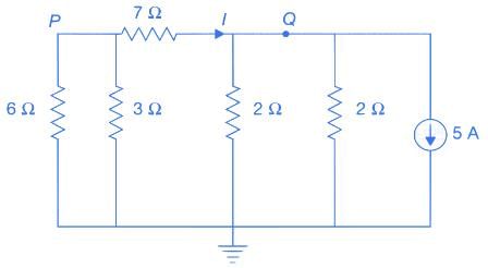
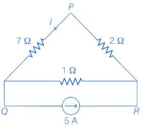
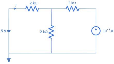
The current I flowing through the 7Ω resistor between P and Q (rounded off to one decimal place) is ______ A
Source Transformation Technique
We know that there are two practical sources, namely, voltage source and current source. We can transform (convert) one source into the other based on the requirement, while solving network problems.
The technique of transforming one source into the other is called as source transformation technique. Following are the two possible source transformations:
- Practical voltage source into a practical current source
- Practical current source into a practical voltage source
Practical Voltage Source into a Practical Current Source
The transformation of practical voltage source into a practical current source is shown in the following figure: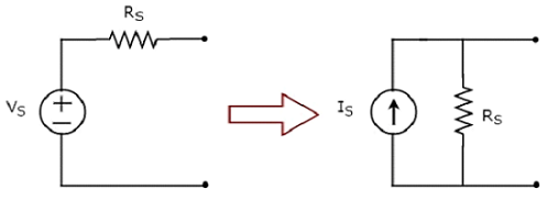
Practical voltage source consists of a voltage source (VS) in series with a resistor (RS). This can be converted into a practical current source as shown in the figure. It consists of a current source (IS) in parallel with a resistor (RS).
The value of IS will be equal to the ratio of VS and RS. Mathematically, it can be represented as
Practical Current Source into a Practical Voltage Source
The transformation of practical current source into a practical voltage source is shown in the following figure: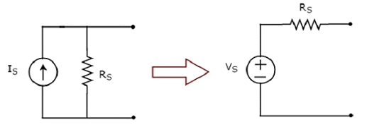
- Practical current source consists of a current source (IS) in parallel with a resistor (RS). This can be converted into a practical voltage source as shown in the figure.
- It consists of a voltage source (VS) in series with a resistor (RS).
- The value of VS will be equal to the product of IS and RS. Mathematically, it can be represented as VS = ISRS
Another type of Active Elements:
Some active elements are different types of transistors, generators, batteries , independent sources, Op Amps,etc
|
73 videos|139 docs|62 tests
|
FAQs on Active Elements: Network Theory - Network Theory (Electric Circuits) - Electrical Engineering (EE)
| 1. What are independent sources in electrical engineering? |  |
| 2. Can you explain what dependent sources are in network theory? |  |
| 3. How can the source transformation technique be used in electrical engineering? |  |
| 4. How can a practical voltage source be transformed into a practical current source? |  |
| 5. How can a practical current source be transformed into a practical voltage source? |  |


