Study Notes For Synchronous Machines - 1

Synchronous Machines
A synchronous machine is an electromechanical device that converts energy from one form to another by interaction between a magnetic field and an electric circuit, operating with alternating current (AC). Its principal feature is that the rotor speed is locked to the rotating magnetic field produced by the stator; hence it runs at a definite speed called the synchronous speed.
- Synchronous machines are widely used as alternating-current generators (alternators) in power stations, as constant-speed motors where precise speed is required, and as devices for power-factor correction in electrical networks.
- They are normally three-phase machines, though single-phase versions exist for special applications.
- Whether used as a generator or a motor, a synchronous machine operates at the synchronous speed determined by the supply frequency and the number of poles.
 Example of Synchronous Machines
- A synchronous machine always runs at a constant speed called the synchronous speed, provided it remains locked (in step) with the rotating stator field.

- Synchronous machines can be classified by the location of their field and armature windings into two broad arrangements: the stationary-field (or rotating-armature) type and the rotating-field type.
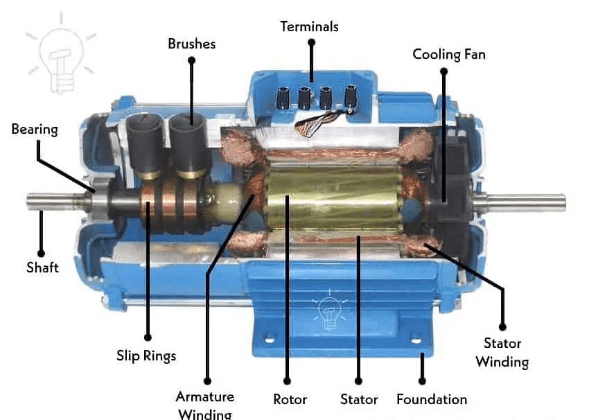
Stationary-field Synchronous Machine
- In this construction the field system (poles) is mounted on the stator (stationary member) and is magnetized either by permanent magnets or by direct current (DC).
- The armature winding (three-phase) is mounted on the rotor and its terminals are brought out through slip-rings and brushes. This arrangement is limited to small ratings (typically up to a few kVA) because of insulation and brush current limitations.
Rotating-field Synchronous Machine
- In the common rotating-field arrangement the field winding is on the rotor and the armature winding is on the stator. The stator supplies three-phase voltage directly to the external network without brushes.
- The rotor field winding is excited by DC current. Excitation is provided either by slip-rings and brushes (external excitation) or by an exciter/diode bridge on the rotor (brushless excitation).
- This rotating-field type is used universally for medium and large machines because it avoids large currents through brushes and allows high power output.
Synchronous Motor and Generator
- A synchronous generator (alternator) produces an alternating emf of constant frequency determined by the rotor speed and number of poles.
- A synchronous motor runs at synchronous speed and can operate with leading, lagging, or unity power factor depending on the rotor excitation; this allows synchronous motors to be used for power-factor correction.
- A synchronous motor running with no mechanical load and suitably excited is called a compensator. When overexcited it supplies reactive power (behaves like a capacitor); when underexcited it absorbs reactive power (behaves like an inductor).
Types of Synchronous Machines
According to the arrangement of the field and armature windings, synchronous machines are classified as:
- Rotating-armature type (stationary field)
- Rotating-field type (stationary armature)
Rotating-Armature Type
- The armature winding is on the rotor and the field is on the stator.
- Generated currents are taken out via slip-rings and brushes.
- Insulation and brush current transmission limits restrict this type to small machines; a common application is as the main exciter for large alternators.
Rotating-Field Type
- The armature winding is on the stator and the field winding is on the rotor.
- Field current is supplied by the exciter through two slip-rings or by brushless arrangements; armature current goes directly to the load without brushes.
- This arrangement is used for virtually all medium and high-power synchronous machines.
According to field shape, synchronous machines are also classified as:
- Cylindrical-rotor (non-salient pole)
- Salient-pole
Cylindrical-Rotor Machines
- Cylindrical rotors are used for high-speed machines such as steam-turbine driven alternators (often two-pole machines).
- The rotor has a small diameter-to-length ratio to limit mechanical stresses caused by centrifugal forces at high speed.
Salient-Pole Machines
- Salient-pole construction is used for low-speed machines (for example, hydro-turbine driven alternators) and many synchronous motors.
- These machines have projecting poles with field coils wound on the pole faces and usually a large diameter-to-length ratio.
- A damper winding (a short-circuited squirrel-cage winding) is typically embedded in the pole faces to aid starting of synchronous motors and improve transient stability.
Basic Operation of the Synchronous Machine
The stator (armature) of a three-phase synchronous machine has distributed windings placed in slots around the stator core. When a balanced three-phase voltage is applied to a properly distributed three-phase winding, the resulting magnetomotive force (MMF) is a rotating MMF of constant magnitude.
- The rotating MMF produces a rotating flux that links the rotor. If the rotor carries a DC field, the rotor poles align and lock with the rotating flux so that the rotor rotates at the same speed as the rotating stator field.
- The speed of the rotating field is the synchronous speed, given by:
Synchronous speed:
Ns = 120 f / P
where f is the electrical frequency (Hz), P is the number of poles, and Ns is in revolutions per minute (rpm).

The developed (unwrapped) view of a multi-pole stator winding shows how each phase occupies slots and how coils run alternately under north and south poles. Different phases are displaced by 120 electrical degrees so that the combined MMF is a rotating vector.
Schematic winding configurations for a two-pole generator commonly used are:
- Two parallel circuits per phase.
- Two series-connected circuits per phase.
- Coil placement in slots may be such that some slots contain coils of only one phase while others contain coils of two phases.
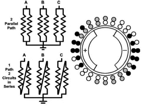 Schematic View of Two-Pole Generator
No-Load Operation
- If the stator terminals are connected to an infinite bus, the stator sees a balanced three-phase voltage V1; the resulting stator MMF (Fs) produces a stator flux φs that rotates at synchronous speed.
- If the rotor field winding carries no DC current (no excitation), the rotor produces no torque and the stator flux alone magnetizes the machine; the induced counter emf (E1) in the armature exactly opposes the applied voltage V1 (neglecting losses), so the armature current is zero or very small.
- If small DC excitation is applied to the rotor but no mechanical torque is on the shaft, rotor excitation partly supplies the flux required for E1, reducing φs; this is the under-excited condition from the stator viewpoint.
Motor Operation
- If an external (braking) torque is applied to the rotor, the rotor tends to fall behind the rotating stator MMF. To maintain synchronism the armature current changes so that the electromagnetic torque develops to balance the applied torque.
- When the machine is under-excited the stator current phasor shifts so that the machine draws reactive power (lagging or leading depending on convention). When over-excited the machine supplies reactive power.
- If the applied braking torque is increased beyond a certain limit the rotor cannot remain locked to the stator field and the machine will pull out of step (stall). The maximum steady torque occurs when the torque-angle δ equals π/2 electrical radians.
- The torque capability depends on the magnitudes of air-gap fluxes from stator and rotor; overexcited machines can deliver greater mechanical output than underexcited ones.
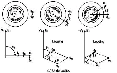 Phasor Diagram of Underexcited Synchronous Machine
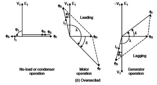 Phasor Diagram of Overexcited Synchronous Machine
The instantaneous active power absorbed by the motor from the network (per phase) is:
Active power = V1 × I1 × cosϕ1
Generator Operation
- When a positive mechanical torque is applied to the rotor (prime mover), the rotor flux leads the stator flux by torque-angle δ and the machine delivers active power to the network. The stator currents change accordingly to maintain the new steady state.
- An under-excited generator (field weak) absorbs reactive power from the system (current leads terminal voltage, i.e., leading power factor at terminals), while an over-excited generator supplies reactive power (lagging current at terminals corresponds to supply of vars to the system depending on sign conventions).
- Generators supplying both watts and vars are normally run in an over-excited condition so they can deliver required reactive power in addition to active power.
Apparent Power and Power Factor
Two practical limits that restrict the power a machine can deliver are the mechanical torque capability of the shaft and the thermal (heating) limit of the windings. In steady state the thermal limit (heating) usually sets the maximum continuous rating.
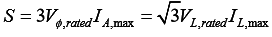
- The maximum allowable armature current - determined by allowable temperature rise in the winding insulation - sets the apparent power rating (kVA) of a synchronous machine.
- The armature heating depends on the magnitude of current regardless of power factor; therefore the rated current determines the kVA rating, not the kW rating.

If the rated terminal voltage is known, the maximum permissible armature current determines the apparent power rating:
Synchronous Machine Ratings
The purpose of machine ratings is to protect equipment from damage and to specify safe operating limits. Typical ratings and nameplate data include terminal voltage, rated speed, apparent power (kVA), rated power factor, field current, frequency and service factor.
- Voltage, speed and frequency: Rated frequency is set by the power system (commonly 50 Hz or 60 Hz; 400 Hz for specialised applications). For a fixed number of poles, only one synchronous speed is possible at the rated frequency.
- If a machine is designed for one frequency and is operated at another, its maximum allowable terminal voltage changes because induced emf Ea = K φ ω; for example, a 60 Hz machine operating at 50 Hz must be derated in voltage to 50/60 (≈ 83.3%) to avoid exceeding flux/voltage limits.

Synchronous Machine Temperature Rating
The maximum permissible temperature rise depends on the insulation class of the winding. Standard insulation classes and the commonly used limits (temperature rise above ambient) are:
- Class A - 60°C above ambient
- Class B - 80°C above ambient
- Class F - 105°C above ambient
- Class H - 125°C above ambient
The higher the insulation class, the greater the allowable temperature rise and the higher the continuous power that can be delivered without damaging the insulation.
Note: Overheating damages insulation and shortens machine life. To allow some margin for applications with uncertain loads, machines are often given a service factor, defined as the ratio of the actual maximum continuous power allowed to the rated plate power. For example, a machine with service factor 1.15 may be operated continuously at 115% of rated load without harm (within manufacturer limits).
Summary
- Synchronous machines run at synchronous speed given by Ns = 120 f / P and are classified by winding arrangement (rotating-armature or rotating-field) and rotor shape (cylindrical or salient-pole).
- Rotating-field machines with stator armature windings are the common form for large machines; field excitation controls reactive power exchange with the system (over-excited → supplies vars; under-excited → absorbs vars).
- Thermal limits set the continuous apparent power rating; insulation class and service factor determine permissible temperature rise and overload capability.
FAQs on Study Notes For Synchronous Machines - 1
| 1. What are the types of synchronous machines? |  |
| 2. How do synchronous machines operate? | |
| 3. What is apparent power and power factor in synchronous machines? | |
| 4. What are the ratings of synchronous machines? | |
| 5. Can synchronous machines be used as both generators and motors? | |


 | Explore Courses for Electrical Engineering (EE) exam |
 | Get EduRev Notes directly in your Google search |