No Load and Blocked Rotor Test | Electrical Machines - Electrical Engineering (EE) PDF Download
| Table of contents |

|
| No Load Test |

|
| Calculations |

|
| Approximate Equivalent Circuit for No-Load Test |

|
| Blocked Rotor Test |

|
| Equivalent Circuit for Blocked Rotor Test |

|
No Load Test
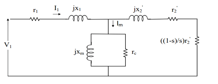
The no load test for an induction machine is like the open circuit test for a transformer. It helps to find the parameters related to the magnetic part (shunt parameters) of the machine's equivalent circuit. In this test, the motor runs without anything connected to its shaft at the rated voltage and frequency. The motor runs close to its synchronous speed, so the slip (how much slower it is than synchronous speed) is almost zero. This makes the rotor's impedance very high, almost like an open circuit.
Because of this, we can simplify the equivalent circuit of the motor. The data we get from this test tells us about the stator and the magnetizing branch of the motor. The setup for the no load test is shown in a diagram. We use readings from voltmeters, ammeters, and wattmeters while the machine is running with no load to find out these parameters.
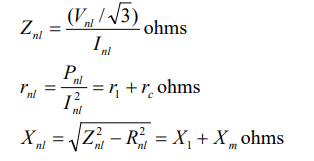
Calculations
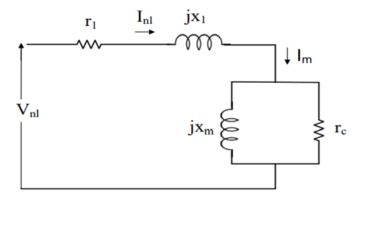
Approximate Equivalent Circuit for No-Load Test
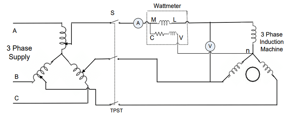
Connection diagram for performing No-load and Blocked Rotor tests on 3 phase Induction machine
 |
Download the notes
No Load and Blocked Rotor Test
|
Download as PDF |
Blocked Rotor Test
The blocked rotor test for an induction machine is like the short circuit test for a transformer. It helps us find out the series parameters of the motor, like its leakage impedances. In this test, the rotor is intentionally stopped from turning, and we apply balanced voltages to the stator terminals at a frequency that is 25% of the rated frequency. We adjust the voltage until we get the rated current flowing through the motor. Under this condition of reduced voltage and rated current, the core loss and the magnetizing part of the current are a very small percentage of the total current. This simplifies the equivalent circuit of the motor.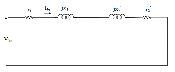
Equivalent Circuit for Blocked Rotor Test
In this test, the slip (how much slower the rotor is moving compared to the magnetic field) is 1, since the rotor is not moving at all. This makes the speed-dependent equivalent resistance almost zero, and the rotor's resistance in the circuit becomes very small.
Because of this, the rotor current becomes much larger than the current in the excitation branch of the circuit, so we can ignore the excitation branch. We measure the voltage and power at the input of the motor during this test.
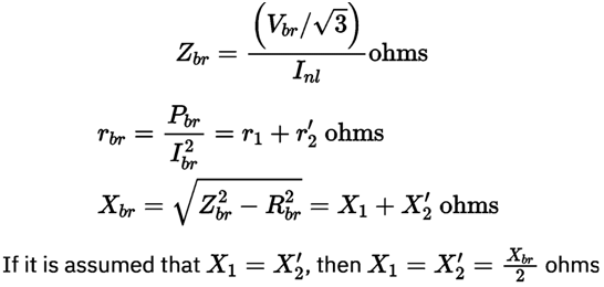
Calculations
|
19 videos|95 docs|25 tests
|

