


All Exams >
Civil Engineering (CE) >
6 Months Preparation for GATE Civil Engg >
All Questions
All questions of Flow Through Pipes for Civil Engineering (CE) Exam
Maximum efficiency of power transmission through pipe is- a)50%
- b)66.67%
- c)75%
- d)100%
Correct answer is option 'B'. Can you explain this answer?
Maximum efficiency of power transmission through pipe is
a)
50%
b)
66.67%
c)
75%
d)
100%

|
Tanishq Nair answered |
Efficiency of Power Transmission through Pipe
Efficiency of power transmission through a pipe can be defined as the ratio of the actual power transmitted to the power supplied.
Factors affecting Efficiency
- Friction losses: Friction between the fluid and the inner surface of the pipe results in energy losses.
- Pipe material and roughness: Smooth pipes reduce friction losses compared to rough pipes.
- Pipe diameter: Larger diameter pipes result in lower friction losses.
Maximum Efficiency
The maximum efficiency of power transmission through a pipe is 66.67%. This is because the remaining 33.33% of the power is lost due to friction losses.
Improving Efficiency
- Using smooth pipes with minimal roughness can reduce friction losses.
- Increasing the pipe diameter can also help in reducing energy losses.
- Proper maintenance of the pipe system can ensure efficient power transmission.
In conclusion, achieving 100% efficiency in power transmission through a pipe is not possible due to unavoidable friction losses. However, by optimizing the pipe material, diameter, and maintenance practices, it is possible to reach a maximum efficiency of 66.67%.

In a sudden contraction, the velocity head changes from 0.5 m to 1.25 m. The coefficient of contraction is 0.66. The head loss in this contraction is- a)0.133 m
- b)0.332 m
- c)0.644 m
- d)0.75 m
Correct answer is option 'B'. Can you explain this answer?
In a sudden contraction, the velocity head changes from 0.5 m to 1.25 m. The coefficient of contraction is 0.66. The head loss in this contraction is
a)
0.133 m
b)
0.332 m
c)
0.644 m
d)
0.75 m

|
Engineers Adda answered |
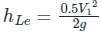
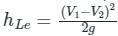
- The head loss in a sudden contraction is calculated using the formula:
Head Loss = (1 - Cc)2 * (V22 - V12)/2g
Given:
- Initial velocity head, V12/2g = 0.5 m
- Final velocity head, V22/2g = 1.25 m
- Cc = 0.66
- Substitute values:
Head Loss = (1 - 0.66)2 * (1.25 - 0.5) = 0.332 m - The correct answer is B: 0.332 m.
In a hydro project, a turbine is mounted in such a way that it acquires a head of 52 m. The water discharge in the feeding penstock with the flow rate of 4000 l/s. If the head loss of 6 m takes place in the penstock and the power of 900 kW is extracted from the turbine, The hydraulic efficiency of the turbine can be considered as 90 %. What should be the residual head loss of the turbine? (Take g = 10 m/s2)- a)12 m
- b)15 m
- c)21 m
- d)52 m
Correct answer is option 'C'. Can you explain this answer?
In a hydro project, a turbine is mounted in such a way that it acquires a head of 52 m. The water discharge in the feeding penstock with the flow rate of 4000 l/s. If the head loss of 6 m takes place in the penstock and the power of 900 kW is extracted from the turbine, The hydraulic efficiency of the turbine can be considered as 90 %. What should be the residual head loss of the turbine? (Take g = 10 m/s2)
a)
12 m
b)
15 m
c)
21 m
d)
52 m
|
|
Anjana Mukherjee answered |
Given:
- Head of the turbine, h = 52 m
- Water discharge in the feeding penstock, Q = 4000 l/s = 4 m³/s
- Head loss in the penstock, h_loss = 6 m
- Power extracted from the turbine, P = 900 kW
- Hydraulic efficiency of the turbine, η = 90%
- Acceleration due to gravity, g = 10 m/s²
To find:
The residual head loss of the turbine.
Solution:
1. Convert the water discharge from liters per second to cubic meters per second:
1 liter = 0.001 cubic meters
Therefore, Q = 4000 * 0.001 = 4 m³/s
2. Calculate the net head available at the turbine:
Net head = Total head - Head loss
Net head = 52 m - 6 m = 46 m
3. Calculate the hydraulic power output of the turbine:
Hydraulic Power = ρ * g * Q * Net head
Where ρ is the density of water.
Assuming the density of water as ρ = 1000 kg/m³,
Hydraulic Power = 1000 * 10 * 4 * 46 = 1840000 W = 1840 kW
4. Calculate the actual power output of the turbine:
Actual Power = Hydraulic Power * Hydraulic Efficiency
Actual Power = 1840 kW * 0.90 = 1656 kW
5. Calculate the residual head loss:
Residual head loss = Total head - Net head
Residual head loss = 52 m - 46 m = 6 m
Therefore, the residual head loss of the turbine is 6 m. Hence, option (c) is correct.
Assertion: The hydraulic power transmitted by a pipe through a certain distance by means of water under pressure will be maximum when the loss of head due to friction over this distance is one-third of the total head supplied.
Reason: The average velocity of flow should be less than the critical velocity which corresponds to the laminar flow. - a)Both A and R are individually true and R is the correct explanation of A
- b)Both A and R are individually true but R is not the correct explanation of A
- c)A is true but R is false
- d)A is false but R is true
Correct answer is option 'B'. Can you explain this answer?
Assertion: The hydraulic power transmitted by a pipe through a certain distance by means of water under pressure will be maximum when the loss of head due to friction over this distance is one-third of the total head supplied.
Reason: The average velocity of flow should be less than the critical velocity which corresponds to the laminar flow.
Reason: The average velocity of flow should be less than the critical velocity which corresponds to the laminar flow.
a)
Both A and R are individually true and R is the correct explanation of A
b)
Both A and R are individually true but R is not the correct explanation of A
c)
A is true but R is false
d)
A is false but R is true

|
Pioneer Academy answered |
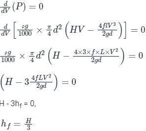
For Assertion:
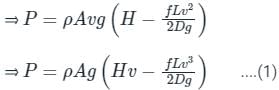
If we are neglecting the entry and exit loss through the pipe and considering the friction loss only through the pipe, then net Power transmitted by the pipe,
⇒ P = ρ × Q × g × (H - hf)
Head loss due to friction in pipe,
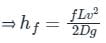
Where,
H = Net head available, v = Velocity through the pipe, L = Length of the pipe, D = Diameter of the pipe, Q = Volume flow rate, f= Darcy friction factor
H = Net head available, v = Velocity through the pipe, L = Length of the pipe, D = Diameter of the pipe, Q = Volume flow rate, f= Darcy friction factor
For maximum power transmission through the pipe,
⇒ dP / dv = 0
By using equation (1),
⇒ hf = H/3
⇒ The hydraulic power transmitted by a pipe through a certain distance by means of water under pressure will be maximum when the loss of head due to friction over this distance is one-third of the total head supplied.
For Reason:
A critical Reynolds number is determined as a limit where the laminar flow changes to turbulent flow. If the calculated Re is greater than the critical Reynolds number Rec, the flow regime is turbulent; otherwise, the flow regime is laminar. The velocity corresponding to the critical Reynolds number is called the critical velocity. For laminar flow, the critical Reynolds number is 2300.
We calculate the Reynolds number by putting the velocity as average velocity in the formula,
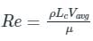
Lc = Characteristic length, Vavg = The average velocity of the flow, μ = Dynamic viscosity of the fluid,, ρ = Density of the fluid,
⇒ The average velocity of flow should be equal to the critical velocity which corresponds to the laminar flow.
⇒ The average velocity of flow should be equal to the critical velocity which corresponds to the laminar flow.
The power transmitted through a pipe is maximum when the loss of head due to friction is given by (H = head supplied)- a)H/4
- b)H/3
- c)H/2
- d)2H/3
Correct answer is option 'B'. Can you explain this answer?
The power transmitted through a pipe is maximum when the loss of head due to friction is given by (H = head supplied)
a)
H/4
b)
H/3
c)
H/2
d)
2H/3
|
|
Pioneer Academy answered |
The power transmitted through a pipe is maximum when the loss of head due to friction is given by (H = head supplied),
hf = H/3
Power transmission through pipes:
hf = H/3
Power transmission through pipes:
- Power is transmitted through pipes by flowing water or other liquids through them.
- Power transmitted through pipes will be dependent over the following factors as mentioned here.
- Rate of flow through the pipe.
- Total head available at the end of the pipe
Now we will consider a tank with which a pipe AB is connected. Let us consider the following terms from figure
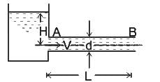
L = Length of the pipe, D = Diameter of the pipe, H = Total head available at the inlet of the pipe, V= Velocity of flow in the pipe, hf = Loss of head due to friction, f = Co-efficient of friction
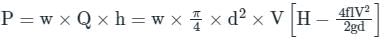
Power transmitted at the outlet of the pipe can be determined by:
P = γQHnet

Condition for maximum transmission of power:
Now we will find here the condition for maximum transmission of power and it could be secured by differentiating the equation of power transmitted at the outlet of the pipe.
L = Length of the pipe, D = Diameter of the pipe, H = Total head available at the inlet of the pipe, V= Velocity of flow in the pipe, hf = Loss of head due to friction, f = Co-efficient of friction
Power transmitted at the outlet of the pipe can be determined by:
P = γQHnet
Condition for maximum transmission of power:
Now we will find here the condition for maximum transmission of power and it could be secured by differentiating the equation of power transmitted at the outlet of the pipe.
In case of power transmission through pipes, maximum efficiency is- a)25%
- b)66.66%
- c)33.3%
- d)50%
Correct answer is option 'B'. Can you explain this answer?
In case of power transmission through pipes, maximum efficiency is
a)
25%
b)
66.66%
c)
33.3%
d)
50%
|
|
Sanvi Kapoor answered |
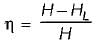
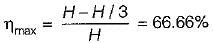
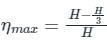
The efficiency of power transmission is given by

Here, H = head available at the inlet, hf = frictional head loss
For maximum efficiency
HL = H/3
We get
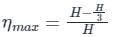
ηmax = 66.66%
Here, H = head available at the inlet, hf = frictional head loss
For maximum efficiency
HL = H/3
We get
ηmax = 66.66%
The head loss due to friction in a pipe of 1 m diameter and 1.5 km long when water is flowing with a velocity of 1 m/s is
(Darcy’s friction factor f = 0.02 and acceleration due to gravity g = 10 m/s2)- a)1.5 m
- b)0.5 m
- c)1 m
- d)2 m
Correct answer is option 'A'. Can you explain this answer?
The head loss due to friction in a pipe of 1 m diameter and 1.5 km long when water is flowing with a velocity of 1 m/s is
(Darcy’s friction factor f = 0.02 and acceleration due to gravity g = 10 m/s2)
(Darcy’s friction factor f = 0.02 and acceleration due to gravity g = 10 m/s2)
a)
1.5 m
b)
0.5 m
c)
1 m
d)
2 m
|
|
Sanya Agarwal answered |
Concept:
Head loss due to friction is given by:

d = diameter of pipe, f = friction factor, L = length of pipe, and v = velocity of flow
Calculation:
Given:
d = 1 m, L = 1.5 km = 1500 m, v = 1 m/s, f = 0.02, g = 10 m/s2
Head loss due to friction is
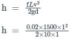
h = 1.5 m
Head loss due to friction is given by:
d = diameter of pipe, f = friction factor, L = length of pipe, and v = velocity of flow
Calculation:
Given:
d = 1 m, L = 1.5 km = 1500 m, v = 1 m/s, f = 0.02, g = 10 m/s2
Head loss due to friction is
h = 1.5 m
Minor losses in a piping system are- a)Less than the friction losses
- b)Due to the viscous stresses
- c)Assumed to vary linearly with the velocity
- d)Found by using loss coefficients
Correct answer is option 'D'. Can you explain this answer?
Minor losses in a piping system are
a)
Less than the friction losses
b)
Due to the viscous stresses
c)
Assumed to vary linearly with the velocity
d)
Found by using loss coefficients
|
|
Sanya Agarwal answered |
Minor loses caused by the disruption of the flow due to the installation of appurtenances, such as valves, bends, and other fittings.
- Minor losses are usually expressed in terms of the loss coefficient KL also called the resistant coefficient and it is defined as,

where KL = loss coefficient, HL = loss of head, V = velocity of fluid
- In some cases, the minor losses may be greater than the major losses, for example, in a system where several turns and valves in a short distance.
Following are some minor losses which occur in pipe flow:
- Loss of energy due to sudden enlargement
- Loss of energy due to sudden contraction
- Loss of energy at the entrance of the pipe
- Loss of energy at the exit from pipe
- Loss of energy in Bends and Pipe Fittings
Maximum efficiency of transmission of power through a pipe is- a)25%
- b)66.66%
- c)33.3%
- d)50%
Correct answer is option 'B'. Can you explain this answer?
Maximum efficiency of transmission of power through a pipe is
a)
25%
b)
66.66%
c)
33.3%
d)
50%
|
|
Nayanika Yadav answered |
Efficiency of power transmission is given by
For maximum efficiency

We get
For maximum efficiency
We get
A fluid of dynamic viscosity 2 × 10⁻⁵ kg/ms and density 1 kg/m3 flows with an average velocity of 1 m/s through a long duct of rectangular (25 mm × 15 mm) cross-section. Assuming laminar flow, the pressure drop (in Pa) in the fully developed region per meter length of the duct is ___________
Correct answer is between '1.75,1.9'. Can you explain this answer?
A fluid of dynamic viscosity 2 × 10⁻⁵ kg/ms and density 1 kg/m3 flows with an average velocity of 1 m/s through a long duct of rectangular (25 mm × 15 mm) cross-section. Assuming laminar flow, the pressure drop (in Pa) in the fully developed region per meter length of the duct is ___________

|
Sameer Verma answered |
The unit of dynamic viscosity is typically expressed in Pascal-seconds (Pa·s) or poise (P). However, you have not provided the units for the given dynamic viscosity value of 2. Please provide the units so that I can accurately answer your question.
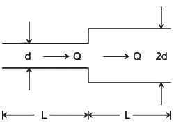
Two pipelines of equal length are connected in series. The diameter of the second pipe is two times that of the first pipe, the ratio of head loss between the first and second pipe is- a)1 : 32
- b)32 : 1
- c)1 : 8
- d)1 : 4
Correct answer is option 'B'. Can you explain this answer?
Two pipelines of equal length are connected in series. The diameter of the second pipe is two times that of the first pipe, the ratio of head loss between the first and second pipe is
a)
1 : 32
b)
32 : 1
c)
1 : 8
d)
1 : 4
|
|
Sanvi Kapoor answered |
Concept:
When two pipelines are connected in series, the total discharge in each pipe will be the same as individual discharges at each pipe to be connected in series
The discharge through the equivalent pipe,
Qtotal = Q1 = Q2
The total head is equal to the sum of head losses at each individual pipe htotal = h1 + h2
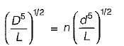
The darcy wisback factor is given as,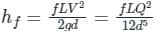
Here, nothing is mentioned the friction factor for both the pipes which are connected in series so here we need to assume that f is the same for each pipe.
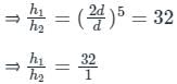
⇒ hf ∝ 1 / d5
Calculation:
Given:
d1 = d, d2 = 2d
Therefore,

When two pipelines are connected in series, the total discharge in each pipe will be the same as individual discharges at each pipe to be connected in series
The discharge through the equivalent pipe,
Qtotal = Q1 = Q2
The total head is equal to the sum of head losses at each individual pipe htotal = h1 + h2
The darcy wisback factor is given as,
Here, nothing is mentioned the friction factor for both the pipes which are connected in series so here we need to assume that f is the same for each pipe.
⇒ hf ∝ 1 / d5
Calculation:
Given:
d1 = d, d2 = 2d
Therefore,
Major energy losses occur due to:- a)Bend in pipe
- b)Pipe fitting’s
- c)Expansion of pipes
- d)Friction
Correct answer is option 'D'. Can you explain this answer?
Major energy losses occur due to:
a)
Bend in pipe
b)
Pipe fitting’s
c)
Expansion of pipes
d)
Friction
|
|
Sanvi Kapoor answered |
There are generally two types of losses that occur in a pipe flow problem:
- Major loss: Major head loss occurs due to friction, which is given by:
- hf = flv2 / 2gd
- Where f = friction factor = 64Re
- Minor head loss: Minor head loss occurs due to:
- Sudden enlargement
- Sudden contraction
- Due to pipe bends
- head loss at the entrance and exit of pipe etc.
Loss of head at the exit of a pipe is given as ________.- a)V3/2g
- b)V3/g
- c)V2/g
- d)V2/2g
Correct answer is option 'D'. Can you explain this answer?
Loss of head at the exit of a pipe is given as ________.
a)
V3/2g
b)
V3/g
c)
V2/g
d)
V2/2g
|
|
Sanya Agarwal answered |
Minor head losses:
- Head loss at entry
- Head loss due to expansion
- Head loss at exit

For a circular pipe with diameter D and having laminar flow, the head loss due to friction is ________.- a)directly proportional to D4
- b)inversely proportional to D4
- c)directly proportional to D2
- d)inversely proportional to D2
Correct answer is option 'B'. Can you explain this answer?
For a circular pipe with diameter D and having laminar flow, the head loss due to friction is ________.
a)
directly proportional to D4
b)
inversely proportional to D4
c)
directly proportional to D2
d)
inversely proportional to D2
|
|
Sanvi Kapoor answered |
Laminar flow through a circular pipe:
In a constant diameter pipe, the pressure drops uniformly along the pipe length (except for the entrance region)
∵ we know that the average velocity through a circular pipe;
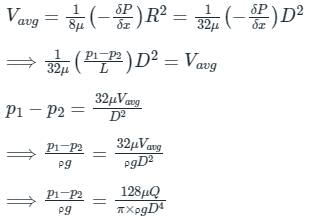
Now, ΔP = ρ g Hl
Putting ΔP, from the above equation, we get
Hl ∝ 1 / D4
From the above expression, it is clear that hydraulic gradient is inversely proportional to D4
In a constant diameter pipe, the pressure drops uniformly along the pipe length (except for the entrance region)
∵ we know that the average velocity through a circular pipe;
Now, ΔP = ρ g Hl
Putting ΔP, from the above equation, we get
Hl ∝ 1 / D4
From the above expression, it is clear that hydraulic gradient is inversely proportional to D4
The frictional resistance for fluids in motion is- a)proportional to the velocity in laminar flow and to the square of the velocity in turbulent flow
- b)proportional to the square of the velocity in laminar flow and to the velocity in turbulent flow
- c)proportional to the velocity in both laminar flow and turbulent flow
- d)proportional to the square of the velocity in both laminar flow and turbulent flow
Correct answer is option 'A'. Can you explain this answer?
The frictional resistance for fluids in motion is
a)
proportional to the velocity in laminar flow and to the square of the velocity in turbulent flow
b)
proportional to the square of the velocity in laminar flow and to the velocity in turbulent flow
c)
proportional to the velocity in both laminar flow and turbulent flow
d)
proportional to the square of the velocity in both laminar flow and turbulent flow
|
|
Anjana Mukherjee answered |
Understanding Fluid Flow and Frictional Resistance
Fluid flow behavior can be characterized by two distinct regimes: laminar flow and turbulent flow. Each regime exhibits different relationships between frictional resistance and velocity.
Laminar Flow
- In laminar flow, fluid particles move in parallel layers with minimal mixing.
- The frictional resistance is directly proportional to the velocity.
- This means that as the velocity increases, the resistance increases linearly.
- Mathematically, this can be expressed as: Frictional Resistance ∝ Velocity.
Turbulent Flow
- In turbulent flow, the fluid particles move chaotically, creating eddies and vortices.
- The frictional resistance becomes proportional to the square of the velocity.
- This indicates that a small increase in velocity results in a significantly larger increase in resistance.
- Mathematically, this can be expressed as: Frictional Resistance ∝ Velocity².
Conclusion
- The key difference between the two flow types lies in the relationship between frictional resistance and velocity.
- In summary:
- Laminar Flow: Frictional Resistance ∝ Velocity
- Turbulent Flow: Frictional Resistance ∝ Velocity²
This distinction is crucial in civil engineering applications, where understanding fluid dynamics influences design considerations for pipelines, channels, and various hydraulic systems. Option 'A' correctly identifies these relationships, emphasizing the fundamental principles of fluid mechanics.
The condition for power transmission by flow through a pipeline to be maximum is that the loss of head of the flow due to friction throughout the pipeline length is:- a)One-third of the total head at inlet end
- b)One-fourth of the total head at inlet end
- c)Three-fourth of the total head at inlet end
- d)One-half of the total head at inlet end
Correct answer is option 'A'. Can you explain this answer?
The condition for power transmission by flow through a pipeline to be maximum is that the loss of head of the flow due to friction throughout the pipeline length is:
a)
One-third of the total head at inlet end
b)
One-fourth of the total head at inlet end
c)
Three-fourth of the total head at inlet end
d)
One-half of the total head at inlet end
|
|
Pioneer Academy answered |
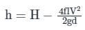
Net available head (h) at the outlet of the pipe is given by:
h = H - hf
Where,
H is the total head at the inlet and hf be the head loss in the transmission.
Power available at the pipe outlet is given by:
For maximum power
dP/dV = 0 → H = 3h
∴ hf = H/3.
h = H - hf
Where,
H is the total head at the inlet and hf be the head loss in the transmission.
Power available at the pipe outlet is given by:
For maximum power
dP/dV = 0 → H = 3h
∴ hf = H/3.
Power transmitted through a pipe is given by
where
w = specific weight of the fluid flowing through pipe
Q = discharge, m3/s- a)wQH
- b)wQHL
- c)wQ(H - HL)
- d)wQ(H + HL)
Correct answer is option 'C'. Can you explain this answer?
Power transmitted through a pipe is given by
where
w = specific weight of the fluid flowing through pipe
Q = discharge, m3/s
where
w = specific weight of the fluid flowing through pipe
Q = discharge, m3/s
a)
wQH
b)
wQHL
c)
wQ(H - HL)
d)
wQ(H + HL)
|
|
Anmol Saini answered |
Power transmitted through a pipe (When HL is frictional head)
P = wQ(H - HL)
P = wQ(H - HL)
Head loss due to friction in water flow through penstock can be minimised by- a)decreasing the diameter of penstock
- b)Increasing the diameter of penstock
- c)Increasing the length of penstock
- d)Increasing the velocity of flow
Correct answer is option 'B'. Can you explain this answer?
Head loss due to friction in water flow through penstock can be minimised by
a)
decreasing the diameter of penstock
b)
Increasing the diameter of penstock
c)
Increasing the length of penstock
d)
Increasing the velocity of flow
|
|
Sanvi Kapoor answered |
The layout of the Hydropower plant is shown below: Components are:

- Reservoir: Reservoirs can be natural (Lake) or Artificial (Dam).
- Penstock: It is a large-diameter pipe that carries water from the water storage system to the turbine.
- Surge tanks: It is a reservoir of water placed near the turbine and is used to avoid the water hammer in the penstock.
- Turbine
- Tailrace
- Generator
Types of head:
- Gross head (HG): It is defined as the head under which a hydropower plant is working or it is the difference between the head race level and tail race level.
- Net head (H): It is the head available with water at the entry to the turbine or it is the head under which the turbine is working.
HG - HF = H; Where HF = Head loss due to friction
According to Darcy's Weisbach equation for head loss in pipes:
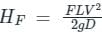 ; where F = Darcy's friction factor = 4f ; where f = friction coefficient
From the above equation, we can see that
HF ∝ L ∝ V2 ∝1D
So, From the above, we can conclude that Head loss due to friction in water flow through the penstock can be minimized by increasing the diameter of the Penstock.
According to Darcy's Weisbach equation for head loss in pipes:
; where F = Darcy's friction factor = 4f ; where f = friction coefficientFrom the above equation, we can see that
HF ∝ L ∝ V2 ∝1D
So, From the above, we can conclude that Head loss due to friction in water flow through the penstock can be minimized by increasing the diameter of the Penstock.
Consider the following statements:
1. Pipe network analysis is normally necessary in analyzing flow in pipes at city water systems,
2. Hardy-cross method of solving pipe network is a method of successive approximations and is not a direct method.
3. The network must satisfy the momentum equation because the flow in each pipe satisfies the head loss equation.
4. Principle of continuity is satisfied in a pipe network..Select the correct statments:- a)1, 2 and 3
- b)2, 3 and 4
- c)1, 3 and 4
- d)1, 2 and 4
Correct answer is option 'B'. Can you explain this answer?
Consider the following statements:
1. Pipe network analysis is normally necessary in analyzing flow in pipes at city water systems,
2. Hardy-cross method of solving pipe network is a method of successive approximations and is not a direct method.
3. The network must satisfy the momentum equation because the flow in each pipe satisfies the head loss equation.
4. Principle of continuity is satisfied in a pipe network..
Select the correct statments:
a)
1, 2 and 3
b)
2, 3 and 4
c)
1, 3 and 4
d)
1, 2 and 4
|
|
Gitanjali Menon answered |
Pipe Network Analysis
Statement 1: Pipe network analysis is normally necessary in analyzing flow in pipes at city water systems.
- Pipe network analysis is an important tool used in hydraulic engineering to determine the flow rates, pressure losses, and head losses in a network of pipes.
- It is particularly important in city water systems where the network can be complex, and the demand for water can be high.
- By analyzing the network, engineers can optimize the design to minimize energy consumption, reduce pipe sizes, and ensure that the pressure and flow requirements are met.
Hardy-Cross Method
Statement 2: Hardy-cross method of solving pipe network is a method of successive approximations and is not a direct method.
- The Hardy-Cross method is a widely used method for solving pipe networks.
- It is an iterative method, which means that the solution is obtained by successive approximations.
- The method involves balancing the head losses around each loop in the network and adjusting the flow rates in each pipe until a solution is reached.
- While the method is not a direct method, it is relatively simple to use, and it can be applied to networks of any size and complexity.
Momentum Equation and Principle of Continuity
Statement 3: The network must satisfy the momentum equation because the flow in each pipe satisfies the head loss equation.
- The momentum equation is a fundamental principle in fluid mechanics that relates the forces acting on a fluid to its mass, velocity, and acceleration.
- In a pipe network, the momentum equation must be satisfied because the flow in each pipe is subject to frictional losses, which cause a loss of momentum.
- The head loss equation, which is used in pipe network analysis, is derived from the momentum equation and is based on the assumption that the flow is steady and incompressible.
- By satisfying the momentum equation, engineers can ensure that the flow rates and pressures in the network are consistent with the physical laws of fluid mechanics.
Statement 4: Principle of continuity is satisfied in a pipe network.
- The principle of continuity is another fundamental principle in fluid mechanics that states that the mass flow rate of a fluid is constant at any given point in a pipe or duct.
- In a pipe network, the principle of continuity must be satisfied because the flow rates at each junction in the network must be balanced.
- The continuity equation, which is used in pipe network analysis, is based on the principle of continuity and is used to calculate the flow rates in each pipe.
- By satisfying the principle of continuity, engineers can ensure that the flow rates in the network are consistent with the physical laws of fluid mechanics.
Conclusion
- In summary, pipe network analysis is an important tool in hydraulic engineering, and the Hardy-Cross method is a widely used method for solving pipe networks.
- The momentum equation and principle of continuity are fundamental principles in fluid mechanics that must be satisfied in a pipe network to ensure that the flow rates and pressures are consistent with the physical laws of fluid mechanics.
Water is pumped through a pipeline to a height of 10 m at the rate of 0.1 m3 /s, friction and other minor losses are 5 m. pumping power required in kW is- a)13.3
- b)14.7
- c)20
- d)9.8
Correct answer is option 'B'. Can you explain this answer?
Water is pumped through a pipeline to a height of 10 m at the rate of 0.1 m3 /s, friction and other minor losses are 5 m. pumping power required in kW is
a)
13.3
b)
14.7
c)
20
d)
9.8
|
|
Sanvi Kapoor answered |
Concept:
Pumping power required to pump water to a height of H against head loss hf is given by :
Power P = γw Q(H + hf)
Whereγw = unit weight of water, Q = Rate of flow, H = Pumping height, hf = friction and other minor losses
Due to losses, total height against which power is required = H + hf
Solution:
Given, Pumping height (H) = 10 m, Total Head Loss (hf) = 5 m, Rate of flow (Q) = 0.1 m3/sec and γw = = 9.81 kN/m3
Pumping Power required to lift water:
P = γw Q(H+hf) = 9.81 × 103 × 0.1 × (10 + 5) = 14.715 × 10³ W
P = 14.715 kW
Therefore pumping power required is 14.715 kW
Water (density = 1000 kg/m3) at ambient temperature flows through a horizontal pipe of uniform cross section at the rate of 1 kg/s. If the pressure drop across the pipe is 100 kPa, the minimum power required to pump the water across the pipe, in watts, is ________
Correct answer is '100'. Can you explain this answer?
Water (density = 1000 kg/m3) at ambient temperature flows through a horizontal pipe of uniform cross section at the rate of 1 kg/s. If the pressure drop across the pipe is 100 kPa, the minimum power required to pump the water across the pipe, in watts, is ________
|
|
Pioneer Academy answered |
Concept:
Power is required to overcome losses, hf
Power = ρQgh
where h = frictional head loss
the frictional head loss will be equal to the pressure difference head
hence ρh = ΔP / ρg
Calculation:
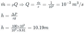
Power = 9810 × 10-3 × 10.19 = 100 W
Power is required to overcome losses, hf
Power = ρQgh
where h = frictional head loss
the frictional head loss will be equal to the pressure difference head
hence ρh = ΔP / ρg
Calculation:
Power = 9810 × 10-3 × 10.19 = 100 W
For a fully–developed flow of water in a pipe having a diameter 10 cm, velocity 0.2 m/s, and kinetic viscosity 10-5 m2/s, what is the value of the Darcy friction factor?- a)6.4
- b)0.032
- c)0.064
- d)0.64
Correct answer is option 'B'. Can you explain this answer?
For a fully–developed flow of water in a pipe having a diameter 10 cm, velocity 0.2 m/s, and kinetic viscosity 10-5 m2/s, what is the value of the Darcy friction factor?
a)
6.4
b)
0.032
c)
0.064
d)
0.64

|
Mrinalini Chavan answered |
Functional system, there are several components that need to be present and working together effectively. These components include:
1. Hardware: This refers to the physical components of the system, such as the computer, server, storage devices, and networking equipment. It is important to have reliable and compatible hardware to ensure the system can perform its functions effectively.
2. Operating System: The operating system is the software that manages and controls the hardware resources of the system. It provides a platform for other software applications to run and facilitates communication between the hardware and software components.
3. Software Applications: These are the programs and applications that perform specific tasks or functions. They can range from basic productivity tools like word processors and spreadsheets to more complex enterprise software systems like customer relationship management (CRM) or enterprise resource planning (ERP).
4. Data: Data is the information that is input, processed, and output by the system. It can be stored locally on the system or accessed remotely through a network. Data should be organized and structured in a way that allows for efficient processing and retrieval.
5. Network: A network is necessary for communication and connectivity between different components of the system. It enables data sharing, remote access, and collaboration. A reliable and secure network infrastructure is essential for a fully functional system.
6. Security: Security measures are crucial to protect the system and its data from unauthorized access, breaches, and threats. This includes implementing firewalls, encryption, access controls, and regular system updates to patch vulnerabilities.
7. User Interface: The user interface allows users to interact with the system and perform tasks. It should be intuitive, user-friendly, and responsive. A well-designed user interface enhances user productivity and satisfaction.
8. Maintenance and Support: Ongoing maintenance and support are necessary to ensure the system continues to function optimally. This includes regular updates, bug fixes, and troubleshooting. Adequate support channels should be in place to address user queries and issues.
All these components need to be integrated and configured properly to create a fully functional system that meets the requirements and objectives of its users.
The power available at the outlet of the pipe carrying water with a rate of flow of Q and an head of H supplied at the entrance of the pipe is
(γ is the specific weight: and hf is the loss of head due to friction)- a)γQ(H - hf)
- b)γQH
- c)γQ(H + hf)
- d)γQH/(H + hf)
Correct answer is option 'A'. Can you explain this answer?
The power available at the outlet of the pipe carrying water with a rate of flow of Q and an head of H supplied at the entrance of the pipe is
(γ is the specific weight: and hf is the loss of head due to friction)
(γ is the specific weight: and hf is the loss of head due to friction)
a)
γQ(H - hf)
b)
γQH
c)
γQ(H + hf)
d)
γQH/(H + hf)
|
|
Sanvi Kapoor answered |
The power transmitted through a pipe is maximum when the loss of head due to friction is given by (H = head supplied),
hf = H/3
Power transmission through pipes:
hf = H/3
Power transmission through pipes:
- Power is transmitted through pipes by flowing water or other liquids through them.
- Power transmitted through pipes will be dependent over the following factors as mentioned here.
- Rate of flow through the pipe.
- Total head available at the end of the pipe
Now we will consider a tank with which a pipe AB is connected. Let us consider the following terms from figure
L = Length of the pipe, D = Diameter of the pipe, H = Total head available at the inlet of the pipe, V= Velocity of flow in the pipe, hf = Loss of head due to friction, f = Co-efficient of friction
Power transmitted at the outlet of the pipe can be determined by:
P = γQHnet
P = ρQgHnet
L = Length of the pipe, D = Diameter of the pipe, H = Total head available at the inlet of the pipe, V= Velocity of flow in the pipe, hf = Loss of head due to friction, f = Co-efficient of friction
Power transmitted at the outlet of the pipe can be determined by:
P = γQHnet
P = ρQgHnet
The minor loss due to sudden contraction is due to- a)flow contraction
- b)expansion of flow after sudden contraction
- c)boundary friction
- d)cavitation
Correct answer is option 'B'. Can you explain this answer?
The minor loss due to sudden contraction is due to
a)
flow contraction
b)
expansion of flow after sudden contraction
c)
boundary friction
d)
cavitation
|
|
Akash Kapoor answered |
In sudden contraction, right after the sudden contraction Ac , a vena contracta is formed; and then, right after, the flow widens again to fill the entire pipe. The region between the wall interior pipe and the vena contracta will be a region of separated flow. The flow pattern after the vena contracta is similar to that after an abrupt enlargement and the loss is caused due to expansion of flow after sudden contraction.
Which of the following is not a minor energy loss?- a)Loss due to sudden enlargement
- b)Loss due to friction
- c)Loss due to entrance of pipe
- d)Loss due to bend in pipe
Correct answer is option 'B'. Can you explain this answer?
Which of the following is not a minor energy loss?
a)
Loss due to sudden enlargement
b)
Loss due to friction
c)
Loss due to entrance of pipe
d)
Loss due to bend in pipe

|
Subhankar Ghoshal answered |
Loss due to friction is not a minor energy loss.
Explanation:
Frictional loss is a major energy loss that occurs when fluid (liquid or gas) flows through a pipe or conduit. It is also known as "major head loss" as it contributes significantly to the overall energy loss in a fluid flow system.
Frictional loss occurs due to the interaction between the flowing fluid and the inner surface of the pipe. As the fluid moves through the pipe, it experiences resistance from the pipe walls, resulting in a loss of energy. This energy loss is primarily attributed to the viscous shear forces between the fluid layers and the pipe surface.
Frictional losses can be calculated using various equations, such as the Darcy-Weisbach equation or the Hazen-Williams equation, depending on the characteristics of the flow and the pipe material. These equations take into account factors such as pipe roughness, flow velocity, pipe diameter, and fluid properties to estimate the frictional losses.
The other options mentioned in the question, i.e., loss due to sudden enlargement, loss due to entrance of pipe, and loss due to bend in the pipe, are all minor energy losses. These losses are typically referred to as "minor head losses" because they occur at specific locations in the flow system and are relatively smaller compared to the frictional loss.
- Loss due to sudden enlargement: When the cross-sectional area of a pipe suddenly increases, the flow undergoes an expansion, resulting in a loss of energy. This loss is due to the conversion of kinetic energy into potential energy as the fluid expands.
- Loss due to entrance of pipe: When fluid enters a pipe, it experiences a contraction at the entrance due to the difference in cross-sectional areas. This contraction causes a localized energy loss.
- Loss due to bend in the pipe: When a fluid flows through a curved section of a pipe, it experiences a change in direction, leading to a loss of energy. This loss is attributed to the generation of secondary flow patterns and increased turbulence.
While these minor losses should not be ignored, they are relatively smaller compared to the frictional loss and can be accounted for using empirical equations or experimental data.
Three identical pipes of length L, diameter D and friction factor f, are connected in parallel between two reservoirs. The size of a pipe of length L and of same friction factor f, equivalent to the above pipes, is- a)D
- b)1.22 D
- c)1.55 D
- d)1.86 D
Correct answer is option 'C'. Can you explain this answer?
Three identical pipes of length L, diameter D and friction factor f, are connected in parallel between two reservoirs. The size of a pipe of length L and of same friction factor f, equivalent to the above pipes, is
a)
D
b)
1.22 D
c)
1.55 D
d)
1.86 D
|
|
Avinash Sharma answered |
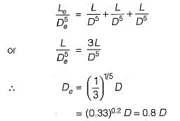
Equivalent pipe for the pipes in parallel:
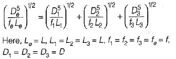
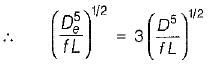
or
or De = 1.5518 D
or
or De = 1.5518 D
The pressure drop for a relatively low Reynolds number flow in a 600 mm diameter, 30 m long pipeline is 70 kPa. What is the wall shear stress?- a)0 Pa
- b)1400 Pa
- c)700 Pa
- d)350 Pa
Correct answer is option 'D'. Can you explain this answer?
The pressure drop for a relatively low Reynolds number flow in a 600 mm diameter, 30 m long pipeline is 70 kPa. What is the wall shear stress?
a)
0 Pa
b)
1400 Pa
c)
700 Pa
d)
350 Pa
|
|
Sanya Agarwal answered |
Concept:
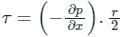
Shear stress at any distance ‘r’ from the center of the pipe is given by.
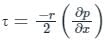
At r = R, i.e. at the, pipe wall, shear stress is maximum and is given by
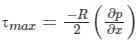
Where, R = Radius of the pipe
∂p / x = Pressure gradient over the length of the pipe.
So, from the above, τ ∝ R
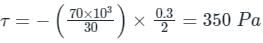
Calculation:
Given:
δp = 70 kPa, r = 300 mm, x = 30 m
Shear stress
Shear stress at any distance ‘r’ from the center of the pipe is given by.
At r = R, i.e. at the, pipe wall, shear stress is maximum and is given by
Where, R = Radius of the pipe
∂p / x = Pressure gradient over the length of the pipe.
So, from the above, τ ∝ R
Calculation:
Given:
δp = 70 kPa, r = 300 mm, x = 30 m
Shear stress
Assertion A: Loss of head at a sudden expansion of a pipe is larger than that at a sudden contraction.
Reason R: Separation of flow occurs at sudden contractionsWhich of the following is correct?- a)A is false but R is true.
- b)A is true but R is false.
- c)Both A and R are true, but R is not a correct explanation of A.
- d)Both A and R are true, and R is the correct explanation of A.
Correct answer is option 'C'. Can you explain this answer?
Assertion A: Loss of head at a sudden expansion of a pipe is larger than that at a sudden contraction.
Reason R: Separation of flow occurs at sudden contractionsWhich of the following is correct?
Reason R: Separation of flow occurs at sudden contractionsWhich of the following is correct?
a)
A is false but R is true.
b)
A is true but R is false.
c)
Both A and R are true, but R is not a correct explanation of A.
d)
Both A and R are true, and R is the correct explanation of A.
|
|
Divya Kulkarni answered |
Assertion A: Loss of head at a sudden expansion of a pipe is larger than that at a sudden contraction.
Reason R: Separation of flow occurs at sudden contractions
The correct answer to this question is option 'C', which states that both Assertion A and Reason R are true, but R is not a correct explanation of A.
Explanation:
Loss of head at a sudden expansion of a pipe:
When the flow of fluid passes through a sudden expansion in a pipe, the velocity of the fluid decreases, resulting in an increase in pressure. This increase in pressure is due to the conversion of kinetic energy into potential energy. The loss of head at a sudden expansion is a result of this pressure increase.
Loss of head at a sudden contraction of a pipe:
When the flow of fluid passes through a sudden contraction in a pipe, the velocity of the fluid increases, resulting in a decrease in pressure. This decrease in pressure is due to the conversion of potential energy into kinetic energy. The loss of head at a sudden contraction is a result of this pressure decrease.
Separation of flow at sudden contractions:
The reason given for Assertion A is that separation of flow occurs at sudden contractions. This means that when the fluid passes through a sudden contraction, there is a tendency for the flow to separate from the pipe walls, leading to disturbances and turbulence in the flow. This separation of flow results in additional energy losses, contributing to the overall loss of head.
Correct explanation:
While it is true that separation of flow occurs at sudden contractions, it is not the only factor contributing to the loss of head at a sudden contraction. The increase in velocity and decrease in pressure also play significant roles in the overall loss of head. Therefore, Reason R is not a correct explanation of Assertion A.
In conclusion, both Assertion A and Reason R are true. However, Reason R is not a correct explanation of Assertion A.
A pipe 100 mm in diameter and 981 m long delivers water at a velocity of 1.0 m/s. The loss of head, when the coefficient of friction in pipe f = 0.0008, is- a)6.4
- b)1.6
- c)3.2
- d)12.8
Correct answer is option 'B'. Can you explain this answer?
A pipe 100 mm in diameter and 981 m long delivers water at a velocity of 1.0 m/s. The loss of head, when the coefficient of friction in pipe f = 0.0008, is
a)
6.4
b)
1.6
c)
3.2
d)
12.8

|
Rhea Dasgupta answered |
Loss of head in a pipe is the energy loss due to friction between the flowing fluid and the pipe walls. It is also known as head loss or pressure loss. In this question, we are given the diameter of the pipe, the length of the pipe, the velocity of the water, and the coefficient of friction. We need to calculate the loss of head.
Loss of Head Formula:
The loss of head in a pipe can be calculated using the Darcy-Weisbach equation:
hL = f * (L / D) * (v^2 / 2g)
where:
hL = loss of head (m)
f = coefficient of friction (dimensionless)
L = length of the pipe (m)
D = diameter of the pipe (m)
v = velocity of the water (m/s)
g = acceleration due to gravity (9.81 m/s^2)
Given Data:
Diameter of the pipe (D) = 100 mm = 0.1 m
Length of the pipe (L) = 981 m
Velocity of the water (v) = 1.0 m/s
Coefficient of friction (f) = 0.0008
Calculation:
Substituting the given values into the loss of head formula:
hL = 0.0008 * (981 / 0.1) * (1.0^2 / 2 * 9.81)
hL = 0.0008 * (9810) * (1.0 / 19.62)
hL = 0.0008 * 500
hL = 0.4 m
Therefore, the loss of head in the pipe is 0.4 m.
Answer:
The correct option is B) 1.6 m.
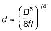
The diameter of the nozzle (d) for maximum transmission of power is given by
Where
D = Diameter of pipe
f = Darcy’s friction factor
l = Length of pipe
- a) d = (D5/8fl)1/2
- b)d = (D5/8fl)1/3
- c)d = (D5/8fl)1/5
- d)d = (D5/8fl)1/4
Correct answer is option 'D'. Can you explain this answer?
The diameter of the nozzle (d) for maximum transmission of power is given by
Where
D = Diameter of pipe
f = Darcy’s friction factor
l = Length of pipe
Where
D = Diameter of pipe
f = Darcy’s friction factor
l = Length of pipe
a)
d = (D5/8fl)1/2
b)
d = (D5/8fl)1/3
c)
d = (D5/8fl)1/5
d)
d = (D5/8fl)1/4

|
Nishanth Banerjee answered |
For maximum power transmission through nozzle:
Nozzle diameter
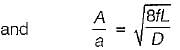
A = area of supply pipe
a = area of Nozzle
Nozzle diameter
A = area of supply pipe
a = area of Nozzle
When flow velocity in a pipe is increased by 10%, the loss of head due to friction increases by- a)21%
- b)25%
- c)5%
- d)11%
Correct answer is option 'A'. Can you explain this answer?
When flow velocity in a pipe is increased by 10%, the loss of head due to friction increases by
a)
21%
b)
25%
c)
5%
d)
11%
|
|
Rohan Singh answered |
Explanation:
When the flow velocity in a pipe is increased by 10%, the loss of head due to friction increases by 21%.
Loss of head due to friction:
Loss of head due to friction in a pipe is given by the Darcy-Weisbach equation:
Where:
- h is the head loss due to friction
- f is the Darcy-Weisbach friction factor
- L is the length of the pipe
- D is the diameter of the pipe
- V is the velocity of the flow
- g is the acceleration due to gravity
Relationship between head loss and velocity:
The head loss due to friction is directly proportional to the square of the velocity of the flow. Therefore, when the flow velocity is increased, the head loss due to friction also increases.
Relationship between head loss and flow velocity:
To determine the relationship between the head loss due to friction and the flow velocity, we can take the derivative of the Darcy-Weisbach equation with respect to the flow velocity.
This equation shows that the rate of change of head loss with respect to flow velocity is directly proportional to the friction factor, length, and diameter of the pipe.
Calculation:
Given that the flow velocity is increased by 10%, we can assume that the friction factor, length, and diameter of the pipe remain constant. Therefore, the rate of change of head loss with respect to flow velocity remains the same.
Let's say the initial head loss due to friction is h1, and the final head loss due to friction is h2.
Using the relationship between the two equations, we can determine the relationship between h1 and h2.
This shows that when the flow velocity is increased by 10%, the head loss due to friction increases by 10%.
However, the question states that the head loss due to friction increases by 21%. This means that there must be some other factors contributing to the increase in head loss, such as changes in pipe roughness or additional fittings in the pipe.
When the flow velocity in a pipe is increased by 10%, the loss of head due to friction increases by 21%.
Loss of head due to friction:
Loss of head due to friction in a pipe is given by the Darcy-Weisbach equation:
h = f (L/D) (V^2/2g)
Where:
- h is the head loss due to friction
- f is the Darcy-Weisbach friction factor
- L is the length of the pipe
- D is the diameter of the pipe
- V is the velocity of the flow
- g is the acceleration due to gravity
Relationship between head loss and velocity:
The head loss due to friction is directly proportional to the square of the velocity of the flow. Therefore, when the flow velocity is increased, the head loss due to friction also increases.
Relationship between head loss and flow velocity:
To determine the relationship between the head loss due to friction and the flow velocity, we can take the derivative of the Darcy-Weisbach equation with respect to the flow velocity.
dh/dV = f (L/D) V/g
This equation shows that the rate of change of head loss with respect to flow velocity is directly proportional to the friction factor, length, and diameter of the pipe.
Calculation:
Given that the flow velocity is increased by 10%, we can assume that the friction factor, length, and diameter of the pipe remain constant. Therefore, the rate of change of head loss with respect to flow velocity remains the same.
Let's say the initial head loss due to friction is h1, and the final head loss due to friction is h2.
dh1/dV = f (L/D) V/g
dh2/dV = f (L/D) (1.1V)/g
Using the relationship between the two equations, we can determine the relationship between h1 and h2.
(dh2/dV) / (dh1/dV) = (f (L/D) (1.1V)/g) / (f (L/D) V/g)
(dh2/dV) / (dh1/dV) = 1.1
This shows that when the flow velocity is increased by 10%, the head loss due to friction increases by 10%.
However, the question states that the head loss due to friction increases by 21%. This means that there must be some other factors contributing to the increase in head loss, such as changes in pipe roughness or additional fittings in the pipe.
Three identical pipes of lenght L, diameter D and friction factor f, are connected in series between two reservoirs. The size of a pipe of length L and of the same friction factor f, equivalent to above pipeline, is- a)0.5 D
- b)0.8 D
- c)0.9 D
- d)D
Correct answer is option 'B'. Can you explain this answer?
Three identical pipes of lenght L, diameter D and friction factor f, are connected in series between two reservoirs. The size of a pipe of length L and of the same friction factor f, equivalent to above pipeline, is
a)
0.5 D
b)
0.8 D
c)
0.9 D
d)
D
|
|
Rajdeep Nambiar answered |
When the flow is such that one third of the static head is consumed in pipe friction, the power delivered by the given pipeline will be:- a)Zero
- b)Unity
- c)Same as always
- d)Maximum
Correct answer is option 'D'. Can you explain this answer?
When the flow is such that one third of the static head is consumed in pipe friction, the power delivered by the given pipeline will be:
a)
Zero
b)
Unity
c)
Same as always
d)
Maximum
|
|
Sanvi Kapoor answered |
Efficiency of power transmission is given by

For maximum efficiency
HL = H/3
We get
ηmax = 66.66%
Hence when the flow is such that one third of the static head is consumed in pipe friction, the power delivered by the given pipeline will be maximum.
For maximum efficiency
HL = H/3
We get
ηmax = 66.66%
Hence when the flow is such that one third of the static head is consumed in pipe friction, the power delivered by the given pipeline will be maximum.
The frictional resistance for fluids in motion is- a)inversely proportional to the square of the surface area of contact
- b)inversely proportional to the surface area of contact
- c)proportional to the square of the surface area of contact
- d)proportional to the surface area of contact
Correct answer is option 'D'. Can you explain this answer?
The frictional resistance for fluids in motion is
a)
inversely proportional to the square of the surface area of contact
b)
inversely proportional to the surface area of contact
c)
proportional to the square of the surface area of contact
d)
proportional to the surface area of contact
|
|
Sanvi Kapoor answered |
According to the laws of fluid friction, the frictional resistance is proportional to the surface area of contact for both laminar and turbulent flows.
Which one of the following is a major loss?- a)frictional loss
- b)shock loss
- c)entry loss
- d)exit loss
Correct answer is option 'A'. Can you explain this answer?
Which one of the following is a major loss?
a)
frictional loss
b)
shock loss
c)
entry loss
d)
exit loss
|
|
Sanvi Kapoor answered |
The major loss for the flflow through the pipes is due to the frictional resistance between adjacent fluid layers sliding over each other. All other losses are considered to be minor losses.
The pressure head loss experienced by fluid flow due to friction in a pipe reduces with- a)Increased length of pipe
- b)Increased diameter of pipe
- c)Decreased length of pipe
- d)Both b and c
Correct answer is option 'D'. Can you explain this answer?
The pressure head loss experienced by fluid flow due to friction in a pipe reduces with
a)
Increased length of pipe
b)
Increased diameter of pipe
c)
Decreased length of pipe
d)
Both b and c
|
|
Sanya Agarwal answered |
Frictional Head Loss in Pipe
- Frictional energy loss per length of the pipe depends on the flow velocity, pipe length, pipe diameter, and a friction factor based on the roughness of the pipe, and whether the flow is laminar or turbulent (i.e. the Reynolds number of the flow).
- The total energy of the fluid conserves as a consequence of the law of conservation of energy.
- In reality, the head loss due to friction results in an equivalent increase in the internal energy (increase in temperature) of the fluid.
- The most common equation used to calculate frictional head losses in a tube or pipet is the Darcy–Weisbach equation (head loss form).
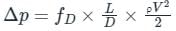
where Δp = pressure loss, fD = darcy friction factor, L = length of pipe, D = hydraulic diameter, V = fluid flow average velocity, ρ = fluid density.
As head loss or pressure loss due to friction in the pipe is
- Directly proportional to the length of the pipe
- Inversely proportional to the diameter of the pipe.
Hence the reduction in length and increase in diameter of the pipe will reduce frictional head or pressure loss.

In network of pipes- a)the head loss around each elementary circuit must be zero
- b)the head loss in all circuits in the same
- c)the elevation of H.G.L is assumed for each junction
- d)elementary circuits are replaced by equivalent pipes
Correct answer is option 'A'. Can you explain this answer?
In network of pipes
a)
the head loss around each elementary circuit must be zero
b)
the head loss in all circuits in the same
c)
the elevation of H.G.L is assumed for each junction
d)
elementary circuits are replaced by equivalent pipes
|
|
Rounak Saini answered |
Head Loss in Network of Pipes
Head loss is a reduction in the total head (pressure) of a fluid as it flows through a network of pipes. To ensure efficient flow and pressure distribution in a network of pipes, certain considerations must be taken into account. These considerations include:
Elementary Circuits
An elementary circuit is a closed loop of pipes that starts and ends at the same point. In a network of pipes, the head loss around each elementary circuit must be zero. This means that the head loss in the circuit is the same as the head gain, resulting in no net loss of head. If the head loss around an elementary circuit is not zero, it can lead to an imbalance in the network, causing flow problems.
Equivalent Pipes
Elementary circuits can be replaced by equivalent pipes to simplify calculations. An equivalent pipe is a single pipe that has the same head loss as the elementary circuit it replaces. By replacing all the elementary circuits with equivalent pipes, the network can be reduced to a single pipe system, making it easier to calculate the head loss and flow rate.
Elevation of H.G.L
The H.G.L (hydraulic grade line) is an imaginary line that represents the pressure of the fluid in the network of pipes. The elevation of the H.G.L is assumed for each junction in the network to ensure that the flow is consistent throughout the system. This assumption helps to avoid problems with pressure imbalances and flow disruptions.
Head Loss in All Circuits
While the head loss around each elementary circuit must be zero, the head loss in all circuits in the network may not be the same. This is because different circuits may have different lengths, diameters, and fittings, resulting in varying head losses. However, the overall head loss in the network must be within an acceptable range to ensure efficient flow and pressure distribution.


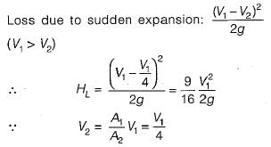
On which of the factors does the co-efficent of bend in a pipe depend?- a)angle of bend and radius of curvature of the bend
- b)angle of bend and radius of the pipe
- c)radius of curvature of the bend and pipe
- d)radius of curvature of the bend and pipe and angle of bend
Correct answer is option 'D'. Can you explain this answer?
On which of the factors does the co-efficent of bend in a pipe depend?
a)
angle of bend and radius of curvature of the bend
b)
angle of bend and radius of the pipe
c)
radius of curvature of the bend and pipe
d)
radius of curvature of the bend and pipe and angle of bend
|
|
Sanvi Kapoor answered |
The co-efficent of bend in a pipe depends on all the three parameters – radius of curvature of the bend, diameter (radius) of the pipe and angle of bend.
A pipe has a welt rounded entrance from a reservoir. If the head loss at the entrance is expressed a the value of K would be about
- a)0.02
- b)0.2
- c)0.5
- d)1.0
Correct answer is option 'A'. Can you explain this answer?
A pipe has a welt rounded entrance from a reservoir. If the head loss at the entrance is expressed a the value of K would be about
the value of K would be abouta)
0.02
b)
0.2
c)
0.5
d)
1.0
|
|
Anjali Datta answered |
Head loss for well rounded entrance as compared to sharp cornered entrance is very small.
 The length of a pipe of 15 cm diameter 2fif {f = 0.03) equivalent to this loss is
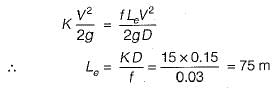
Two pipe systems in series are said to be equivalent when- a)the average diameter in both systems is the same. .
- b)the discharge under the same heacj is same in both systems,
- c)the average friction factor in both systems is the same.
- d)total length of the pipe is the same in both the systems.
Correct answer is option 'B'. Can you explain this answer?
Two pipe systems in series are said to be equivalent when
a)
the average diameter in both systems is the same. .
b)
the discharge under the same heacj is same in both systems,
c)
the average friction factor in both systems is the same.
d)
total length of the pipe is the same in both the systems.
|
|
Sahana Choudhary answered |
Equivalent Two Pipe Systems in Series
The question is related to the concept of equivalent two pipe systems in series. Let's discuss the correct answer, which is option 'B.'
Discharge under the Same Head in Both Systems
When two pipe systems are in series, they are said to be equivalent when the discharge under the same head is the same in both systems. This means that the flow rate of the fluid in both systems is the same when the pressure head is the same.
Reasoning
The reason behind this is that when two pipe systems are in series, the flow rate of the fluid remains constant, and the head loss is distributed between the two systems. Therefore, the discharge under the same head should be the same in both systems.
Other Options
The other options mentioned in the question are not correct because:
- Option 'A' - The average diameter of the pipe does not determine the equivalence of the two pipe systems in series because the diameter of the pipe affects the flow rate and head loss, which can be different in both systems.
- Option 'C' - The average friction factor of the pipe also affects the head loss, which can be different in both systems.
- Option 'D' - The total length of the pipe also affects the head loss, which can be different in both systems.
Conclusion
In conclusion, when two pipe systems are in series, they are said to be equivalent when the discharge under the same head is the same in both systems. This indicates that the flow rate of the fluid is the same in both systems when the pressure head is the same.
At a sudden expansion in a horizontal pipe- a)total energy line rises in the direction of flow
- b)velocity head increasing in the direction of flow
- c)H.G.L rises in the direction of flow
- d)T.E.L is below H.G.L
Correct answer is option 'C'. Can you explain this answer?
At a sudden expansion in a horizontal pipe
a)
total energy line rises in the direction of flow
b)
velocity head increasing in the direction of flow
c)
H.G.L rises in the direction of flow
d)
T.E.L is below H.G.L
|
|
Amar Desai answered |
Expansion in a Horizontal Pipe and the Effect on Energy Lines
When fluid flows through a pipe, it possesses different forms of energy, including pressure energy, kinetic energy, and potential energy. The fluid's total energy can be defined as the sum of these three energies. The energy lines illustrate the distribution of total energy along the pipe's length, while the hydraulic grade line (H.G.L) represents the pressure energy distribution.
At a sudden expansion in a horizontal pipe, the flow area increases, causing a change in the fluid's velocity and pressure distribution, resulting in the following effects:
H.G.L rises in the direction of flow
The hydraulic grade line (H.G.L) represents the pressure energy distribution, and it is a measure of the pressure head of the fluid. At a sudden expansion, the flow area increases, causing a decrease in the fluid's velocity and an increase in its pressure. This increase in pressure causes the H.G.L to rise in the direction of flow.
Total energy line rises in the direction of flow
The total energy line (T.E.L) represents the sum of all three forms of energy, including pressure, kinetic, and potential energies. At a sudden expansion, the flow area increases, causing a decrease in the fluid's velocity and an increase in pressure. This increase in pressure causes the T.E.L to rise in the direction of flow.
Velocity head decreasing in the direction of flow
The velocity head is the kinetic energy of the fluid per unit weight. At a sudden expansion, the flow area increases, causing a decrease in the fluid's velocity. This decrease in velocity causes the velocity head to decrease in the direction of flow.
Conclusion
In conclusion, at a sudden expansion in a horizontal pipe, the flow area increases, causing a decrease in the fluid's velocity and an increase in its pressure. This increase in pressure causes the H.G.L and T.E.L to rise in the direction of flow, while the velocity head decreases in the direction of flow.
In a pipeline, the H.G.L is above the pipe center line in the longitudinal section at point A and below the pipe center line at another point B.
From this it can be inferred that- a)negative pressure prevails at A and positive pressure prevails at B.
- b)positive pressure prevails at A and negative pressure prevails at B.
- c)positive pressure prevails at both A and B.
- d)negative pressure,prevails at both A and B
Correct answer is option 'B'. Can you explain this answer?
In a pipeline, the H.G.L is above the pipe center line in the longitudinal section at point A and below the pipe center line at another point B.
From this it can be inferred that
From this it can be inferred that
a)
negative pressure prevails at A and positive pressure prevails at B.
b)
positive pressure prevails at A and negative pressure prevails at B.
c)
positive pressure prevails at both A and B.
d)
negative pressure,prevails at both A and B

|
Bibek Mukherjee answered |
Explanation:
The given statement indicates that the hydraulic gradient line (H.G.L) is above the pipe center line at point A and below the pipe center line at point B. From this information, we can infer that:
1. Definition of H.G.L
The hydraulic gradient line (H.G.L) represents the total energy line in a pipeline. It is the line connecting the static head and the velocity head of the fluid in the pipeline.
2. Pressure Variation
When the H.G.L is above the pipe center line, it indicates that the pressure is negative or less than atmospheric pressure. Similarly, when the H.G.L is below the pipe center line, it indicates that the pressure is positive or greater than atmospheric pressure.
3. Point A
As per the given statement, the H.G.L is above the pipe center line at point A. Therefore, the pressure at point A is negative or less than atmospheric pressure.
4. Point B
On the other hand, the H.G.L is below the pipe center line at point B. Therefore, the pressure at point B is positive or greater than atmospheric pressure.
5. Conclusion
Hence, from the above observations, we can conclude that positive pressure prevails at point A and negative pressure prevails at point B. Therefore, the correct answer is option 'B'.
In summary, the given statement indicates the variation in pressure along a pipeline, based on the position of the hydraulic gradient line (H.G.L) relative to the pipe center line. It highlights the importance of the H.G.L in determining the pressure distribution in a pipeline.
Friction factor in Darcy’s Weisbach formula is ________.- a)4F'
- b)8F'L
- c)10F'V2
- d)5F'
Correct answer is option 'A'. Can you explain this answer?
Friction factor in Darcy’s Weisbach formula is ________.
a)
4F'
b)
8F'L
c)
10F'V2
d)
5F'
|
|
Sanvi Kapoor answered |
Darcy Weisbach Equation for friction losses in circular pipe:
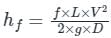
where,
L = length of the pipe, D = diameter of the circular pipe, V = mean velocity of the flow, f = Darcy’s friction factor = 4 × F’, F’ = coefficient of friction, hf = head loss due to friction
For Laminar Flow
Friction Fcator
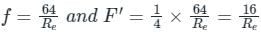
For Turbulent flow

where,
L = length of the pipe, D = diameter of the circular pipe, V = mean velocity of the flow, f = Darcy’s friction factor = 4 × F’, F’ = coefficient of friction, hf = head loss due to friction
For Laminar Flow
Friction Fcator
For Turbulent flow
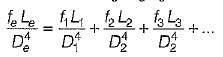
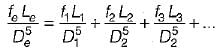
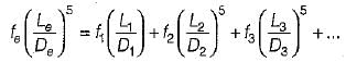
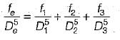


Chapter doubts & questions for Flow Through Pipes - 6 Months Preparation for GATE Civil Engg 2025 is part of Civil Engineering (CE) exam preparation. The chapters have been prepared according to the Civil Engineering (CE) exam syllabus. The Chapter doubts & questions, notes, tests & MCQs are made for Civil Engineering (CE) 2025 Exam. Find important definitions, questions, notes, meanings, examples, exercises, MCQs and online tests here.
Chapter doubts & questions of Flow Through Pipes - 6 Months Preparation for GATE Civil Engg in English & Hindi are available as part of Civil Engineering (CE) exam.
Download more important topics, notes, lectures and mock test series for Civil Engineering (CE) Exam by signing up for free.
6 Months Preparation for GATE Civil Engg
488 videos|1261 docs|878 tests
|
|
© EduRev
|
Education Revolution
|


|


Signup to see your scores
go up
within 7 days!
within 7 days!
Takes less than 10 seconds to signup