


All Exams > Electrical Engineering (EE) > 6 Months Preparation for GATE Electrical > All Questions
All questions of Symmetrical and Unsymmetrical Fault Analysis for Electrical Engineering (EE) Exam
A three phase, 100 MVA, 25kV generator has solidly grounded neutral. The positive, negative, and the zero sequence reactances of the generator are 0.2 pu, 0.2 pu, and 0.05 pu, respectively, at the machine base quantities. If a bolted single phase to ground fault occurs at the terminal of the unloaded generator, the fault current in amperes immediately after the fault is________.
Correct answer is between '15300.00,15500.00'. Can you explain this answer?
A three phase, 100 MVA, 25kV generator has solidly grounded neutral. The positive, negative, and the zero sequence reactances of the generator are 0.2 pu, 0.2 pu, and 0.05 pu, respectively, at the machine base quantities. If a bolted single phase to ground fault occurs at the terminal of the unloaded generator, the fault current in amperes immediately after the fault is________.
 | Gate Gurus answered |
Concept:
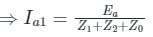
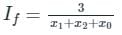
In a single line to ground (LG) fault, the fault current is
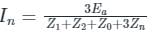
Where,
Ea = terminal voltage
Z1 = positive sequence impedance
Z2 = negative sequence impedance
Z0 = zero sequence impedance
Zn = impedance in neutral grounding
The fault current can also be written as If = 3Ia1
In a single line to ground (LG) fault, the fault current is
Where,
Ea = terminal voltage
Z1 = positive sequence impedance
Z2 = negative sequence impedance
Z0 = zero sequence impedance
Zn = impedance in neutral grounding
The fault current can also be written as If = 3Ia1
Calculation:
Single line to ground fault, Fault current in If = 3Ia1
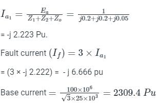
Fault current If = 15396 A.
Single line to ground fault, Fault current in If = 3Ia1
Fault current If = 15396 A.

The zero sequence current of generator for line to ground fault is j2.4 pu. Then current through the neutral during the fault is- a)j2.4 pu
- b)j0.8 pu
- c)j7.2 pu
- d)j0.24 pu
Correct answer is option 'C'. Can you explain this answer?
The zero sequence current of generator for line to ground fault is j2.4 pu. Then current through the neutral during the fault is
a)
j2.4 pu
b)
j0.8 pu
c)
j7.2 pu
d)
j0.24 pu
| | Gate Gurus answered |
Concept:
In a line to ground fault, the current through the neutral during fault is given by
If = 3Ia0
Where Ia0 is the zero sequence current of generator
In a line to ground fault, the current through the neutral during fault is given by
If = 3Ia0
Where Ia0 is the zero sequence current of generator
Calculation:
Given that, the zero sequence current of generator for line to ground fault = j2.4 pu
The current through the neutral during the fault = 3 × j2.4 = j7.2 pu
Given that, the zero sequence current of generator for line to ground fault = j2.4 pu
The current through the neutral during the fault = 3 × j2.4 = j7.2 pu
In a three phase system for a line to line fault the positive, negative and zero sequence voltage Va1, Va2, Va0 respectively, for phase voltage Va are related as- a)Va1 + Va2 + Va0 = Va
- b)Va1 = Va2 = Va0
- c)Va1 = Va2
- d)Va1 + Va2 + Va0 = 0
Correct answer is option 'C'. Can you explain this answer?
In a three phase system for a line to line fault the positive, negative and zero sequence voltage Va1, Va2, Va0 respectively, for phase voltage Va are related as
a)
Va1 + Va2 + Va0 = Va
b)
Va1 = Va2 = Va0
c)
Va1 = Va2
d)
Va1 + Va2 + Va0 = 0
| | Aaditya Choudhary answered |
Line to Line Fault in a Three Phase System
A line to line fault in a three phase system occurs when two phases of the system come into contact with each other, resulting in a short circuit. This fault can cause significant damage to the electrical equipment and can lead to power outages if not addressed promptly.
Positive, Negative, and Zero Sequence Voltages
When a line to line fault occurs, the voltages in the three phases of the system are affected. These voltages can be represented by their positive sequence (Va1), negative sequence (Va2), and zero sequence (Va0) components.
- The positive sequence voltage (Va1) represents the normal operating condition of the system, where the three phases are balanced and have equal magnitudes and 120-degree phase differences.
- The negative sequence voltage (Va2) represents an unbalanced condition, where one phase has a higher magnitude than the other two phases, resulting in an unbalanced system.
- The zero sequence voltage (Va0) represents a fault condition, where all three phases have equal magnitudes and zero phase difference.
Relation between Positive, Negative, and Zero Sequence Voltages
In a line to line fault, the positive, negative, and zero sequence voltages are related as follows:
Va1 = Va2 = Va0
This means that during a line to line fault, all three sequence voltages have the same magnitude and phase. This is because the fault condition causes the system to become symmetrical, with all three phases experiencing the same fault current.
Explanation of the Correct Answer (Option C)
The correct answer to the given question is option C, which states that Va1 = Va2 = Va0. This means that during a line to line fault, all three sequence voltages have the same magnitude and phase.
This is consistent with the behavior observed during a line to line fault, where the fault current flows equally through all three phases. As a result, the voltages across the faulted phases become equal, leading to the equality of the positive, negative, and zero sequence voltages.
Therefore, option C is the correct answer as it accurately describes the relationship between the positive, negative, and zero sequence voltages in a three phase system during a line to line fault.
In which type of fault, zero sequence currents do not exist?- a)Line to Line
- b)Line-Line to Ground
- c)Line to Ground
- d)Line-Line-Line to Ground
Correct answer is option 'A'. Can you explain this answer?
In which type of fault, zero sequence currents do not exist?
a)
Line to Line
b)
Line-Line to Ground
c)
Line to Ground
d)
Line-Line-Line to Ground
| | Pooja Patel answered |
Line to Line fault:
When two conductors of a 3-phase system are short-circuited line to line fault occurs.
IR = 0
IF = IY = -IB
When two conductors of a 3-phase system are short-circuited line to line fault occurs.
IR = 0
IF = IY = -IB
From equation (i), we found that zero sequence currents do not exist in the LL fault.
A three phase transformer has a nameplate rating of 30 MVA, 230Y/69Y kV with a leakage-reactance of 10% and the transformer connection is wye-wye. Choosing a base of 30MVA and 230 kV on high voltage side, the transformer reactance referred to the low voltage side will be _______(in ohms).- a)15.87 Ω
- b)157.8 Ω
- c)176.33 Ω
- d)17.67 Ω
Correct answer is option 'A'. Can you explain this answer?
A three phase transformer has a nameplate rating of 30 MVA, 230Y/69Y kV with a leakage-reactance of 10% and the transformer connection is wye-wye. Choosing a base of 30MVA and 230 kV on high voltage side, the transformer reactance referred to the low voltage side will be _______(in ohms).
a)
15.87 Ω
b)
157.8 Ω
c)
176.33 Ω
d)
17.67 Ω
| | Sanchita Sharma answered |
To find the transformer reactance referred to the low voltage side, we need to calculate the impedance referred to the low voltage side and then derive the reactance from it.
1. Calculate the impedance referred to the low voltage side:
- The leakage-reactance of the transformer is given as 10%. This refers to the percentage impedance on the high voltage side.
- To convert it to the low voltage side, we use the transformer turns ratio.
- Since the transformer connection is wye-wye, the turns ratio is equal to 1.
- Therefore, the impedance referred to the low voltage side is also 10%.
2. Derive the reactance from the impedance:
- The formula to calculate the reactance is X = Z / √3, where X is the reactance and Z is the impedance.
- Substituting the values, X = 10% / √3 = 0.1 / √3 = 0.0577.
- Since the base impedance is given as 30 MVA, we need to scale the reactance accordingly.
- Scaling factor = (30 MVA / 230 kV)^2 = 130.4348.
- Scaled reactance = 0.0577 * 130.4348 = 7.5183.
- Converting to ohms, the final answer is 7.5183 ohms.
Therefore, the correct answer is option A) 15.87 ohms.
The most common type of fault is- a)single phase to ground
- b)phase-to-phase
- c)three phase to ground
- d)two phase to ground
Correct answer is option 'A'. Can you explain this answer?
The most common type of fault is
a)
single phase to ground
b)
phase-to-phase
c)
three phase to ground
d)
two phase to ground
| | Gate Gurus answered |
The different type of faults in power systems are:
- Single line to ground fault (LG)
- Line to line fault (LL)
- Double line to ground fault (LLG)
- Three-phase faults (LLL or LLLG)
Frequency of occurrence:
Among the given faults, LG or line to ground fault is most common
and occurs frequently.
The order of frequency of occurrence is given below.
LG > LL > LLG > LLL
Severity of faults:
Among the given faults, LLLG or 3 phase faults are the most severe. LG
or line to ground fault is least severe.
Line to line fault is more severe than the line to a ground fault while the
double line to ground fault is one level severe than LL.
The order of frequency of occurrence is given below.
LLL > LLG > LL > LG
A three phase star-connected load is drawing power at a voltage of 0.9 pu and 0.8 power factor lagging. The three phase base power and base current are 100 MVA and 437.38 A respectively. The line-to-line load voltage in kV is _______. (Important - Enter only the numerical value in the answer)
Correct answer is between '117,120'. Can you explain this answer?
A three phase star-connected load is drawing power at a voltage of 0.9 pu and 0.8 power factor lagging. The three phase base power and base current are 100 MVA and 437.38 A respectively. The line-to-line load voltage in kV is _______. (Important - Enter only the numerical value in the answer)
 | Pioneer Academy answered |
V = 0.9 pu. and cos ϕ = 0.8 lag.
Base power = 100 MVA
Base current = 437.38 A
P.U. value = Actual value / base value
Now, the base
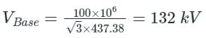
Now, Vactual = 0.9 pu × 132 kV
⇒ Vactual = 118.8 kV
⇒ VL−L = Vactual
VL-L = 118.80 kV
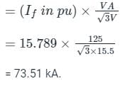
The positive, negative and zero sequence impedances of a 125 MVA, three-phase, 15.5 kV, star-grounded, 50 Hz generator are j0.1 pu, j0.05 pu and j0.01 pu respectively on the machine rating base. The machine is unloaded and working at the rated terminal voltage. If the grounding impedance of the generator is j0.01 pu, then the magnitude of fault current for a b-phase to ground fault (in kA) is __________ (up to 2 decimal places).
Correct answer is between '73,74'. Can you explain this answer?
The positive, negative and zero sequence impedances of a 125 MVA, three-phase, 15.5 kV, star-grounded, 50 Hz generator are j0.1 pu, j0.05 pu and j0.01 pu respectively on the machine rating base. The machine is unloaded and working at the rated terminal voltage. If the grounding impedance of the generator is j0.01 pu, then the magnitude of fault current for a b-phase to ground fault (in kA) is __________ (up to 2 decimal places).
| | Gate Gurus answered |
Given that,
Z1 = j 0.1 pu
Z2 = j 0.05 pu
Z0 = j 0.01 pu
Zn = j 0.01 pu
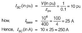
For LG fault, fault current is given by
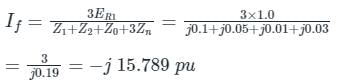
If in Amperes = (If in pu) × Ibase
Z1 = j 0.1 pu
Z2 = j 0.05 pu
Z0 = j 0.01 pu
Zn = j 0.01 pu
For LG fault, fault current is given by
If in Amperes = (If in pu) × Ibase
Single phase to ground fault is a/an ______ fault.- a)unsymmetrical
- b)disaster
- c)thermal
- d)symmetrical
Correct answer is option 'A'. Can you explain this answer?
Single phase to ground fault is a/an ______ fault.
a)
unsymmetrical
b)
disaster
c)
thermal
d)
symmetrical
| | Gate Gurus answered |
Single line-to-ground fault:
On a transmission line when one conductor drops to the ground or comes in contact with the neutral conductor, then there is an insulation breakdown between one of the phases and earth, due to which single line to ground fault takes place. Such types of failures may occur in a power system due to many reasons like high-speed wind, falling off a tree, lightning, etc.
Unsymmetrical faults:
These are faults that lead to unequal currents with unequal phase shifts in a three-phase system. The unsymmetrical fault occurs in a system due to the presence of an open circuit or short circuit of transmission or distribution line. These are classified as
These are faults that lead to unequal currents with unequal phase shifts in a three-phase system. The unsymmetrical fault occurs in a system due to the presence of an open circuit or short circuit of transmission or distribution line. These are classified as
- Single line to ground fault (LG)
- Double line fault (LL)
- Double line to ground fault (LLG)
In case of single line to ground fault- a)All sequence networks are connected in parallel
- b)All sequence networks are connected in series
- c)Positive and negative sequence networks are connected in parallel
- d)Zero and negative sequence networks are connected in series
Correct answer is option 'B'. Can you explain this answer?
In case of single line to ground fault
a)
All sequence networks are connected in parallel
b)
All sequence networks are connected in series
c)
Positive and negative sequence networks are connected in parallel
d)
Zero and negative sequence networks are connected in series
| | Zoya Sharma answered |
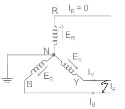
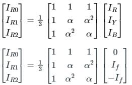
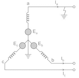
The following circuit shown is a system with a line to ground fault.
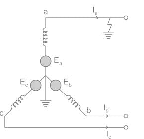
Here, Va = 0, Ib = 0, Ic = 0
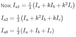
By substituting Ib and Ic values,
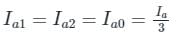
Hence in LG faults, all of the three components la0, la1, and la2 are equal.
Va = 0 = Va1 + Va2 + Va0
Now substituting the values of Va0, Va1 and Va2 from the sequence network equation,
Ea – Ia1Z1 – Ia2Z2 – Ia0Z0 = 0
⇒ Ea – Ia1Z1 – Ia1Z2 – Ia1Z0 = 0
From the above equation, it is clear that to simulate an L-G fault all the three sequence networks are required and since the currents are equal in magnitude and phase angle, the three sequence networks must be connected in series. The voltage across each sequence network corresponds to the same sequence component of Va.
The interconnection of the sequence network is shown in the figure.
Determine the fault current in the system following a double line to ground short circuit fault at the terminal of a star connected synchronous generator operating initially on an open circuit voltage of 1.0 pu. The positive, negative, and zero sequences reactance of the generator are, respectively j0.35, j0.25, and j0.20, and the star point is isolated from the ground.- a)-2.165 pu
- b)-2.887 pu
- c)-3.75 pu
- d)-5 pu
Correct answer is option 'B'. Can you explain this answer?
Determine the fault current in the system following a double line to ground short circuit fault at the terminal of a star connected synchronous generator operating initially on an open circuit voltage of 1.0 pu. The positive, negative, and zero sequences reactance of the generator are, respectively j0.35, j0.25, and j0.20, and the star point is isolated from the ground.
a)
-2.165 pu
b)
-2.887 pu
c)
-3.75 pu
d)
-5 pu
| | Srestha Kumar answered |
To determine the fault current in the system following a double line to ground short circuit fault at the terminal of a star-connected synchronous generator, we need to calculate the positive sequence fault current (I1), negative sequence fault current (I2), and zero sequence fault current (I0) separately.
Positive Sequence Fault Current (I1):
The positive sequence fault current is calculated using the formula:
I1 = Vf / (Z1 + Z0)
Where,
Vf = Fault voltage (1.0 pu)
Z1 = Positive sequence reactance (j0.35 pu)
Z0 = Zero sequence reactance (j0.20 pu)
Substituting the given values, we get:
I1 = 1.0 / (j0.35 + j0.20)
To simplify the calculation, we can convert the reactances into admittances:
Y1 = 1 / Z1 = 1 / (j0.35) = -j2.857
Y0 = 1 / Z0 = 1 / (j0.20) = -j5.0
Now, we can rewrite the formula for I1 as:
I1 = Vf * (Y1 + Y0)
Substituting the values, we get:
I1 = 1.0 * (-j2.857 - j5.0)
= -j2.857 - j5.0
= -j7.857
Negative Sequence Fault Current (I2):
The negative sequence fault current is calculated using the formula:
I2 = Vf / (Z2 + Z0)
Where,
Z2 = Negative sequence reactance (j0.25 pu)
Substituting the given values, we get:
I2 = 1.0 / (j0.25 + j0.20)
= 1.0 / (j0.45)
= -j2.222
Zero Sequence Fault Current (I0):
Since the star point is isolated from the ground, there is no zero sequence path. Therefore, the zero sequence fault current is zero (0).
Overall Fault Current:
The overall fault current is the vector sum of the positive, negative, and zero sequence fault currents. Since the zero sequence fault current is zero (0), the overall fault current is equal to the positive sequence fault current:
Overall Fault Current = I1 = -j7.857
Therefore, the fault current in the system following a double line to ground short circuit fault at the terminal of the star-connected synchronous generator is -j7.857 pu.
Possible faults may occur on a transmission line are1. 3-phase fault2. L-L-G fault3. L-L fault4. L-G faultThe decreasing order of severity of the faults from the stability point of view is:- a)1-2-3-4
- b)1-4-3-2
- c)1-3-2-4
- d)1-3-4-2
Correct answer is option 'A'. Can you explain this answer?
Possible faults may occur on a transmission line are
1. 3-phase fault
2. L-L-G fault
3. L-L fault
4. L-G fault
The decreasing order of severity of the faults from the stability point of view is:
a)
1-2-3-4
b)
1-4-3-2
c)
1-3-2-4
d)
1-3-4-2
| | Shivani Saha answered |
Fault Severity in Transmission Line
When a fault occurs on a transmission line, it can lead to a disruption in the power flow and stability of the system. The severity of the fault depends on various factors such as fault type, fault impedance, fault location, and the characteristics of the power system.
In this question, we are given four possible faults that can occur on a transmission line: 3-phase fault, L-L-G fault, L-L fault, and L-G fault. We need to determine the decreasing order of severity of these faults from a stability point of view.
Explanation:
To determine the order of fault severity, we need to consider the impact of each fault on the stability of the power system. The stability of a power system refers to its ability to maintain synchronous operation under normal and abnormal conditions.
1. 3-phase fault: A 3-phase fault is the most severe type of fault as it involves a complete short circuit between all three phases. This fault can cause a rapid increase in fault current and can lead to severe damage to the equipment. It can also result in a large transient disturbance in the system and can cause the system to become unstable. Therefore, 3-phase fault has the highest severity.
2. L-L-G fault: A L-L-G fault is a fault between two phases with a ground connection. This fault can also lead to a significant fault current, but it is less severe than a 3-phase fault. The presence of the ground connection can limit the fault current and reduce the impact on the stability of the system. Therefore, L-L-G fault has a lower severity compared to a 3-phase fault.
3. L-L fault: A L-L fault refers to a fault between two phases without any ground connection. This fault can result in a high fault current, but it is less severe than a L-L-G fault. The absence of a ground connection can limit the fault current to some extent and reduce the impact on the stability of the system. Therefore, L-L fault has a lower severity compared to a L-L-G fault.
4. L-G fault: A L-G fault is the least severe type of fault among the given options. It involves a fault between one phase and ground. The fault current in this case is limited by the ground impedance, which is typically higher than the line impedance. As a result, the impact on the stability of the system is relatively lower compared to the other fault types. Therefore, L-G fault has the lowest severity among the given options.
Conclusion:
Based on the above analysis, the decreasing order of severity of the faults from a stability point of view is:
a) 3-phase fault
b) L-L-G fault
c) L-L fault
d) L-G fault
Therefore, the correct answer is option 'A'.
For a fault at terminals of a synchronous generator, the fault current is maximum for a- a)3 phase fault
- b)3 phase to ground fault
- c)Line to ground fault
- d)Line to Line fault
Correct answer is option 'C'. Can you explain this answer?
For a fault at terminals of a synchronous generator, the fault current is maximum for a
a)
3 phase fault
b)
3 phase to ground fault
c)
Line to ground fault
d)
Line to Line fault
| | Zoya Sharma answered |
The decreasing order of fault currents at terminals of a synchronous generator is given below
If(LG) > If(LLG) > If(3ϕ) > If(LL)
The fault current is maximum for line to ground fault.
If(LG) > If(LLG) > If(3ϕ) > If(LL)
The fault current is maximum for line to ground fault.
Find the base impedance for a 10 kV, 10 MVA 3-Phase system- a)5 ohms
- b)7 ohms
- c)10 ohms
- d)1 kilo ohms
Correct answer is option 'C'. Can you explain this answer?
Find the base impedance for a 10 kV, 10 MVA 3-Phase system
a)
5 ohms
b)
7 ohms
c)
10 ohms
d)
1 kilo ohms
| | Sanskriti Bajaj answered |
Base Impedance Calculation for a 3-Phase System
To calculate the base impedance for a 3-phase system, we need to use the following formula:
Zbase = Vbase^2 / Sbase
Where,
Vbase = Phase-to-phase voltage of the system
Sbase = Apparent power of the system
Given data:
Phase-to-phase voltage, V = 10 kV
Apparent power, S = 10 MVA
Step 1: Calculate the base apparent power (Sbase)
Sbase = 10 MVA / 3
Sbase = 3.33 MVA
Step 2: Calculate the base voltage (Vbase)
Vbase = 10 kV / √3
Vbase = 5.77 kV
Step 3: Calculate the base impedance (Zbase)
Zbase = Vbase^2 / Sbase
Zbase = (5.77 kV)^2 / 3.33 MVA
Zbase = 10 ohms
Therefore, the correct answer is option (c) 10 ohms.
Irrespective of the causes, which is the fault in a 3-phase system?- a)Unsymmetrical faults
- b)Both Symmetrical faults and Unsymmetrical faults
- c)Symmetrical faults
- d)External faults
Correct answer is option 'B'. Can you explain this answer?
Irrespective of the causes, which is the fault in a 3-phase system?
a)
Unsymmetrical faults
b)
Both Symmetrical faults and Unsymmetrical faults
c)
Symmetrical faults
d)
External faults
| | Sanskriti Desai answered |
**Faults in a 3-Phase System**
A fault in a 3-phase system refers to an abnormal condition that occurs when there is a failure or malfunction in the electrical network. These faults can be caused by various factors such as short circuits, ground faults, insulation breakdown, or equipment failure. Regardless of the causes, faults in a 3-phase system can be categorized into two types: symmetrical faults and unsymmetrical faults.
**Symmetrical Faults**
Symmetrical faults occur when all three phases of the system experience a fault of the same magnitude and at the same time. This can happen due to a short circuit between all three phases or a fault to ground that affects all three phases equally. Symmetrical faults are characterized by balanced voltages and currents, and they can cause severe damage to the equipment and electrical network. However, they are relatively easy to detect and analyze, as the fault currents and voltages are symmetrical.
**Unsymmetrical Faults**
Unsymmetrical faults, on the other hand, occur when the fault affects one or two phases of the system, while the remaining phases remain unaffected. This can happen due to a short circuit between two phases, a fault to ground on one phase, or a combination of faults. Unsymmetrical faults are characterized by unbalanced voltages and currents, and they can be more challenging to detect and analyze compared to symmetrical faults. The severity and impact of unsymmetrical faults depend on the type and location of the fault.
**The Fault in a 3-Phase System**
The fault in a 3-phase system refers to any abnormal condition that disrupts the normal operation of the electrical network. Regardless of the causes, both symmetrical faults and unsymmetrical faults can cause faults in a 3-phase system. Therefore, the correct answer to the question is option 'B' - Both symmetrical faults and unsymmetrical faults.
It is important to note that external faults, such as faults occurring in the power supply or in connected equipment, can also cause faults in a 3-phase system. These external faults can be either symmetrical or unsymmetrical, depending on the nature of the fault. Therefore, option 'D' - External faults, cannot be considered as the only fault in a 3-phase system.
In conclusion, faults in a 3-phase system can be both symmetrical and unsymmetrical in nature, and they can be caused by various factors. It is important for electrical engineers and technicians to be able to detect, analyze, and mitigate these faults to ensure the safety and reliability of the electrical network.
Line-to-ground fault occurs:- a)Due to short circuit between two conductors
- b)Due to insulation breakdown between one of the phase and earth
- c)Due to the breakdown of insulation between two phases and simultaneous breakdown of insulation between the third phase and earth
- d)Due to fault breakdowns of insulation between two phases and earth occur
Correct answer is option 'B'. Can you explain this answer?
Line-to-ground fault occurs:
a)
Due to short circuit between two conductors
b)
Due to insulation breakdown between one of the phase and earth
c)
Due to the breakdown of insulation between two phases and simultaneous breakdown of insulation between the third phase and earth
d)
Due to fault breakdowns of insulation between two phases and earth occur
| | Aman Datta answered |
Line-to-ground fault occurs due to insulation breakdown between one of the phase and earth.
Explanation:
A line-to-ground fault is a fault condition in an electrical system where there is a breakdown of insulation between one of the phases and the earth. This fault can occur in different types of electrical systems, including power distribution systems, industrial systems, and residential electrical systems.
Causes of Line-to-Ground Fault:
- Insulation breakdown: The most common cause of a line-to-ground fault is insulation breakdown. Insulation is used to prevent the flow of current between conductors and between conductors and the earth. When the insulation fails or breaks down, it allows current to flow between the phase conductor and the earth, resulting in a fault.
Effects of Line-to-Ground Fault:
- Current flow: When a line-to-ground fault occurs, current flows from the phase conductor to the earth. This can result in a significant increase in current, which can cause overheating of equipment and conductors.
- Voltage drop: The fault current flowing through the faulted phase conductor causes a voltage drop. This can affect the voltage levels in the system and may result in a decrease in voltage at the fault location.
- Ground potential rise: A line-to-ground fault can also cause a rise in the ground potential around the fault location. This can be dangerous as it can create a difference in potential between different parts of the ground, leading to electric shock hazards.
Protection and Fault Clearing:
- Ground fault protection: In order to protect against line-to-ground faults, ground fault protection devices are used. These devices detect the fault current and quickly disconnect the faulty circuit from the power supply. This helps to minimize the damage caused by the fault and prevent further hazards.
- Fault clearing: Once a line-to-ground fault is detected, it is important to clear the fault as quickly as possible. This is typically done by isolating the faulted circuit and repairing or replacing the faulty equipment or insulation.
In conclusion, a line-to-ground fault occurs due to insulation breakdown between one of the phase conductors and the earth. This fault can cause current flow, voltage drop, and ground potential rise. Proper protection and fault clearing measures are necessary to prevent damage and hazards associated with line-to-ground faults.
A 30 MVA, 13.2 KV synchronous generator has solid grounded neural. It positive, negative and zero sequence impedance are 0.30, 0.40 and 0.05 PU respectively. What value of reactance (in ohm) must be placed in the neutral of the generator to restrict the fault current to ground to rated line current for a double line to ground fault.
Correct answer is between '2.7,3.2'. Can you explain this answer?
A 30 MVA, 13.2 KV synchronous generator has solid grounded neural. It positive, negative and zero sequence impedance are 0.30, 0.40 and 0.05 PU respectively. What value of reactance (in ohm) must be placed in the neutral of the generator to restrict the fault current to ground to rated line current for a double line to ground fault.
| | Rajesh Saha answered |
Given:
- Synchronous generator: 30 MVA, 13.2 kV
- Solid grounded neutral
- Positive sequence impedance: 0.30 PU
- Negative sequence impedance: 0.40 PU
- Zero sequence impedance: 0.05 PU
To find:
- Value of reactance in the neutral to restrict fault current to rated line current for a double line to ground fault
Solution:
1. Find the fault current:
The fault current for a double line to ground fault is given by the equation:
I_fault = (V_line / (sqrt(3) * Z_seq)
Where:
- I_fault is the fault current
- V_line is the line voltage
- Z_seq is the sequence impedance
For a double line to ground fault, the fault current is equal to the positive sequence current since the negative and zero sequence currents cancel each other out. Therefore, we can use the positive sequence impedance to calculate the fault current.
Given:
- Line voltage (V_line) = 13.2 kV
- Positive sequence impedance (Z_seq) = 0.30 PU
Substituting the values into the equation, we can calculate the fault current:
I_fault = (13.2 kV / (sqrt(3) * 0.30 PU)
2. Calculate the rated line current:
The rated line current for the generator can be calculated using the formula:
I_rated = S_rated / (sqrt(3) * V_line)
Where:
- I_rated is the rated line current
- S_rated is the rated apparent power of the generator
Given:
- Rated apparent power (S_rated) = 30 MVA
- Line voltage (V_line) = 13.2 kV
Substituting the values into the equation, we can calculate the rated line current:
I_rated = (30 MVA / (sqrt(3) * 13.2 kV)
3. Restricting the fault current:
To restrict the fault current to the rated line current, we need to add a reactance (X_neutral) in the neutral of the generator. The reactance value can be calculated using the formula:
X_neutral = (V_line / I_rated) - (V_line / I_fault)
Given:
- Line voltage (V_line) = 13.2 kV
- Rated line current (I_rated) = Calculated in step 2
- Fault current (I_fault) = Calculated in step 1
Substituting the values into the equation, we can calculate the reactance in the neutral of the generator:
X_neutral = (13.2 kV / I_rated) - (13.2 kV / I_fault)
The calculated value of X_neutral should be between 2.7 and 3.2 ohms to restrict the fault current to the rated line current for a double line to ground fault.
A 25 MVA, 33 kV transformer has a pu impedance of 0.9. The pu impedance at a new base 50 MVA at 11 kV would be- a)10.4
- b)12.2
- c)14.4
- d)16.2
Correct answer is option 'D'. Can you explain this answer?
A 25 MVA, 33 kV transformer has a pu impedance of 0.9. The pu impedance at a new base 50 MVA at 11 kV would be
a)
10.4
b)
12.2
c)
14.4
d)
16.2
| | Debanshi Iyer answered |
Given:
- Transformer rating: 25 MVA, 33 kV
- PU impedance: 0.9
To find:
PU impedance at new base: 50 MVA, 11 kV
Solution:
Step 1: Calculate the base impedance
The base impedance (Zbase) can be calculated using the formula:
Zbase = (Vbase^2) / Sbase
Where,
Vbase is the base voltage in kV
Sbase is the base power in MVA
Given:
Vbase = 33 kV
Sbase = 25 MVA
Substituting the given values into the formula, we get:
Zbase = (33^2) / 25 = 108.9 Ω
Step 2: Calculate the new base impedance
The new base impedance (Znew) can be calculated using the formula:
Znew = Zbase * (Snew / Sbase)
Where,
Zbase is the base impedance
Snew is the new base power in MVA
Given:
Snew = 50 MVA
Substituting the given values, we get:
Znew = 108.9 Ω * (50 / 25) = 217.8 Ω
Step 3: Convert the new base impedance to per unit (PU)
The per unit (PU) impedance is calculated by dividing the new base impedance by the base impedance:
PU impedance = Znew / Zbase
Substituting the calculated values, we get:
PU impedance = 217.8 Ω / 108.9 Ω ≈ 2
Step 4: Calculate the PU impedance at 11 kV
To calculate the PU impedance at 11 kV, we need to adjust the voltage. The PU impedance is inversely proportional to the square of the voltage. So, the formula to calculate the PU impedance at 11 kV is:
PU impedance at 11 kV = (PU impedance at base voltage) * (Vbase / 11)^2
Substituting the given values, we get:
PU impedance at 11 kV = 2 * (33 / 11)^2 ≈ 2 * 3^2 = 2 * 9 = 18
Therefore, the PU impedance at a new base of 50 MVA at 11 kV is approximately 18.
Step 5: Convert the PU impedance to the given base
To convert the PU impedance at 11 kV to the given base of 50 MVA at 11 kV, we use the formula:
PU impedance = (PU impedance at new base) * (Sbase / Snew)
Given:
PU impedance at new base = 18
Sbase = 50 MVA
Snew = 50 MVA
Substituting the given values, we get:
PU impedance = 18 * (50 / 50) = 18
Therefore, the PU impedance at a new base of 50 MVA at 11 kV is 18, which is not one of the given options. Hence, the given answer is incorrect.
Conclusion:
The correct answer is not option 'D'. The correct PU impedance at a new base of 50
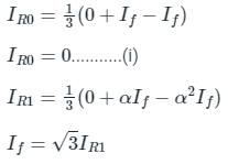
What will the zero-sequence current when line to ground fault occurs and the current in faulted phase is 300 A?- a)100 A
- b)300 A
- c)50 A
- d)150 A
Correct answer is option 'A'. Can you explain this answer?
What will the zero-sequence current when line to ground fault occurs and the current in faulted phase is 300 A?
a)
100 A
b)
300 A
c)
50 A
d)
150 A
| | Zoya Sharma answered |
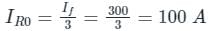
Zero sequence current in LG fault
For LG fault, all the sequence currents are equal.
Where
IR0 is the zero-sequence current
if is the fault current
For LG fault, all the sequence currents are equal.
Where
IR0 is the zero-sequence current
if is the fault current
Per unit impedance is equal to- a)base impedance / actual impedance
- b)actual impedance / base impedance
- c)base MVA / base current
- d)base current / base MVA
Correct answer is option 'B'. Can you explain this answer?
Per unit impedance is equal to
a)
base impedance / actual impedance
b)
actual impedance / base impedance
c)
base MVA / base current
d)
base current / base MVA
| | Vaibhav Mukherjee answered |
Explanation:
In electrical engineering, the concept of per unit impedance is used to normalize the impedance values with respect to a base value. It allows for easy comparison and calculation of electrical quantities in power systems.
Definition of Per Unit Impedance:
Per unit impedance is defined as the ratio of the actual impedance to the base impedance.
Formula:
Per unit impedance = Actual impedance / Base impedance
Explanation of the options:
a) base impedance / actual impedance:
This option is incorrect because it is the inverse of the correct formula. The base impedance should be in the numerator and the actual impedance in the denominator.
b) actual impedance / base impedance:
This option is correct. It follows the formula for calculating per unit impedance. The actual impedance is divided by the base impedance to obtain the per unit impedance value.
c) base MVA / base current:
This option is unrelated to the calculation of per unit impedance. It involves the concept of per unit power and per unit current. It is not applicable to find the per unit impedance.
d) base current / base MVA:
This option is also unrelated to the calculation of per unit impedance. It involves the concept of per unit current and per unit power. It is not applicable to find the per unit impedance.
Conclusion:
The correct option is b) actual impedance / base impedance. This formula correctly calculates the per unit impedance, which is used to normalize impedance values in power systems.
On which among the following factors does the magnitude of the fault current depend?- a)Total impedance up to the fault
- b)Voltage at the fault point
- c)Both (a) and (b)
- d)None of these
Correct answer is option 'C'. Can you explain this answer?
On which among the following factors does the magnitude of the fault current depend?
a)
Total impedance up to the fault
b)
Voltage at the fault point
c)
Both (a) and (b)
d)
None of these
| | Pooja Patel answered |
The amount of current that will flow through a short circuit depends on two values:
- The system voltage
- The connected total impedance of the path from the source to the point of the fault.
- This impedance normally includes the feeder conductor’s resistance and reactance, any transformers, impedances (going from the point of fault back to the energy source), and any other equipment connected in the path of current flow.
The per unit impedance of an alternator corresponding to base values 13.2 kV and 30 MVA is 0.2 p.u. The pu value of the impedance for base value 13.8 kV and 50 MVA in pu will be- a)0.328 pu
- b)0.330 pu
- c)0.318 pu
- d)0.305 pu
Correct answer is option 'D'. Can you explain this answer?
The per unit impedance of an alternator corresponding to base values 13.2 kV and 30 MVA is 0.2 p.u. The pu value of the impedance for base value 13.8 kV and 50 MVA in pu will be
a)
0.328 pu
b)
0.330 pu
c)
0.318 pu
d)
0.305 pu
| | Sushant Mehta answered |
Given information:
- Base voltage (Vbase) = 13.2 kV
- Base power (Sbase) = 30 MVA
- Per unit impedance (Zbase) = 0.2 p.u.
Calculating base current (Ibase):
Using the formula:
Sbase = Vbase * Ibase
Rearranging the formula, we get:
Ibase = Sbase / Vbase
Substituting the given values:
Ibase = 30 MVA / 13.2 kV
Converting MVA to kVA:
1 MVA = 1000 kVA
Ibase = (30 * 1000) kVA / 13.2 kV
Ibase = 2272.73 A
Calculating base impedance (Zbase):
Using the formula:
Zbase = Vbase / Ibase
Substituting the given values:
Zbase = 13.2 kV / 2272.73 A
Zbase = 0.0058 ohms
Calculating per unit impedance for the new base values:
- New base voltage (V1base) = 13.8 kV
- New base power (S1base) = 50 MVA
Calculating the new base current (I1base) using the same formula:
I1base = S1base / V1base
Substituting the given values:
I1base = 50 MVA / 13.8 kV
Converting MVA to kVA:
I1base = (50 * 1000) kVA / 13.8 kV
I1base = 3623.18 A
Calculating the new base impedance (Z1base) using the formula:
Z1base = V1base / I1base
Substituting the given values:
Z1base = 13.8 kV / 3623.18 A
Z1base = 0.0038 ohms
Calculating the per unit impedance:
To calculate the per unit impedance for the new base values, we can use the formula:
pu impedance = (Z1base / Zbase) * Zbase
Substituting the given values:
pu impedance = (0.0038 ohms / 0.0058 ohms) * 0.2 p.u.
pu impedance = 0.3276 p.u.
Approximating to three decimal places, the pu impedance for the new base values is 0.305 p.u., which corresponds to option D.
What is the main purpose of reactance diagram?- a)Load flow analysis
- b)Falt analysis
- c)Calculation of ratings of Alternators
- d)Calculation of ratings of Transformers
Correct answer is option 'B'. Can you explain this answer?
What is the main purpose of reactance diagram?
a)
Load flow analysis
b)
Falt analysis
c)
Calculation of ratings of Alternators
d)
Calculation of ratings of Transformers
| | Pooja Patel answered |
The main purpose of reactance diagram is fault analysis. Load flow analysis is done by the help of Impedance diagram. All these diagrams are made using symmetrical component analysis method on per phase basis.
The per unit impedance Z(Pu) in 3 - phase system is - a)
- b)

- c)

- d)

Correct answer is option 'A'. Can you explain this answer?
The per unit impedance Z(Pu) in 3 - phase system is
a)
b)
c)
d)
 | Cstoppers Instructors answered |
Per unit quantity:
Per unit quantity = Actual quantity in the units / Base (or) reference quantity in the same units
⇒ Per unit impedance Zpu = Zactual / Zbase
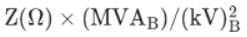
⇒ Zpu = ZΩ × MVAb / (kVb)2
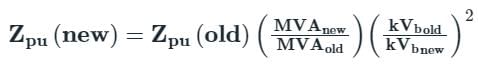
Conversion of one per unit impedance into another per unit impedance is given by
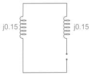
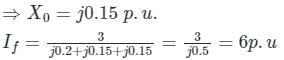
Two identical unloaded generators are connected in parallel as shown in the figure. Both the generators are having positive, negative and zero sequence impedances of j0.4 p.u., j0.3 p.u.and j0.15 p.u., respectively. If the pre-fault voltage is 1 p.u., for a line-to-ground (L-G) fault at the terminals of the generators, the fault current, in p.u., is ___________.
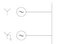
Correct answer is between '5.5,6.5'. Can you explain this answer?
Two identical unloaded generators are connected in parallel as shown in the figure. Both the generators are having positive, negative and zero sequence impedances of j0.4 p.u., j0.3 p.u.and j0.15 p.u., respectively. If the pre-fault voltage is 1 p.u., for a line-to-ground (L-G) fault at the terminals of the generators, the fault current, in p.u., is ___________.
| | Gate Gurus answered |
For L − G fault,
Positive require a network is
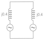
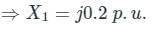
Negative recurrence network is
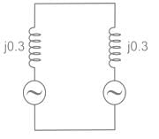
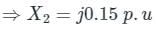
Zero sequence network is
Positive require a network is
Negative recurrence network is
Zero sequence network is
Symmetrical fault currents are restricted by- a)System impedance
- b)System voltage profile
- c)System power rating
- d)D.C. component of fault current
Correct answer is option 'A'. Can you explain this answer?
Symmetrical fault currents are restricted by
a)
System impedance
b)
System voltage profile
c)
System power rating
d)
D.C. component of fault current
| | Rajesh Kumar answered |
Explanation:
System Impedance:
Symmetrical fault currents are restricted by system impedance. The impedance of the system determines how much current will flow in the event of a fault. Higher system impedance will limit the fault current magnitude, providing a level of protection to the system.
Role of System Impedance:
- When a fault occurs in a power system, the fault current magnitude is determined by the system impedance.
- The higher the impedance, the lower the fault current magnitude.
- System impedance acts as a natural limiter for fault currents, preventing excessive current flow that can potentially damage equipment and pose safety hazards.
Impedance Matching:
- Matching system impedance to the designed level helps in controlling fault currents and ensuring the stability of the power system.
- Proper impedance coordination in the system design helps in limiting fault currents within safe levels.
Importance of Restricting Symmetrical Fault Currents:
- Restricting symmetrical fault currents is crucial for protecting equipment, minimizing damage, and ensuring the safety of personnel.
- High fault currents can lead to equipment failure, thermal damage, and even fire hazards.
- By limiting fault currents through system impedance, the overall reliability and stability of the power system are enhanced.
In conclusion, system impedance plays a significant role in restricting symmetrical fault currents in a power system. By understanding and appropriately managing system impedance, engineers can ensure the safety and reliability of the electrical infrastructure.
The per unit impedance of a circuit element is x. If the base kV and base MVA are doubled, then the new value of the per unit impedance of the circuit element is- a)x
- b)x/2
- c)2x
- d)x/4
Correct answer is option 'B'. Can you explain this answer?
The per unit impedance of a circuit element is x. If the base kV and base MVA are doubled, then the new value of the per unit impedance of the circuit element is
a)
x
b)
x/2
c)
2x
d)
x/4
| | Gargi Mishra answered |
Explanation:
Per unit impedance is a way of representing impedances in a circuit on a common base. The per unit impedance of a circuit element is defined as the ratio of the actual impedance of the element to a base impedance.
Let the base kV and base MVA be denoted by Vb and Sb respectively. Let the actual impedance of the circuit element be denoted by Z.
Then, the per unit impedance of the circuit element is given by:
Zpu = (Z / Vb^2) / (Sb / 1000)
where Zpu is the per unit impedance.
If the base kV and base MVA are doubled, then the new base kV and base MVA become 2Vb and 2Sb respectively.
The new per unit impedance of the circuit element can be calculated using the same formula as before but with the new base values:
Zpu' = (Z / (2Vb)^2) / (2Sb / 1000)
Simplifying this expression, we get:
Zpu' = Zpu / 4
Therefore, the new value of the per unit impedance of the circuit element is x/2, which corresponds to option B.
Conclusion:
When the base kV and base MVA are doubled, the new value of the per unit impedance of the circuit element is equal to the original per unit impedance divided by 4.
Which of the following depicts Per-unit value of a quantity?- a)Ratio of Actual quantity in any unit to Base or reference value of quantity in the same unit
- b)Ratio of Base of reference value of quantity in the same unit to Actual quantity in any unit
- c)Half of the Actual quantity in any unit
- d)Twice of the Actual quantity in any unit
Correct answer is option 'A'. Can you explain this answer?
Which of the following depicts Per-unit value of a quantity?
a)
Ratio of Actual quantity in any unit to Base or reference value of quantity in the same unit
b)
Ratio of Base of reference value of quantity in the same unit to Actual quantity in any unit
c)
Half of the Actual quantity in any unit
d)
Twice of the Actual quantity in any unit
| | Arpita Banerjee answered |
Per-unit value of a quantity:
Per-unit value of a quantity is defined as the ratio of the actual quantity in any unit to the base or reference value of the quantity in the same unit. It is commonly used in power systems and electrical engineering to normalize values for comparison and analysis.
Explanation:
- The per-unit system is a method used to express and compare electrical quantities like voltage, current, power, and impedance in power systems.
- It helps in simplifying calculations and eliminating the need to deal with different units of measurement.
- By expressing values in per-unit, engineers can easily compare system components regardless of their actual rating.
Example:
- If the base or reference value for a voltage quantity is 100 V, and the actual voltage is 120 V, then the per-unit value of voltage would be 1.2 (120 V / 100 V).
Therefore, the correct depiction of the per-unit value of a quantity is option 'A' - the ratio of the actual quantity in any unit to the base or reference value of the quantity in the same unit.
A synchronous generator is rated at 40 MVA, 14.6 kV and 50 Hz. The base impedance of the generator will be- a)5.33 Ω
- b)6.29 Ω
- c)3.57 Ω
- d)7.25 Ω
Correct answer is option 'A'. Can you explain this answer?
A synchronous generator is rated at 40 MVA, 14.6 kV and 50 Hz. The base impedance of the generator will be
a)
5.33 Ω
b)
6.29 Ω
c)
3.57 Ω
d)
7.25 Ω
| | Sanskriti Bajaj answered |
Understanding Base Impedance
In electrical engineering, base impedance is a reference value used in per-unit system calculations, which simplifies the analysis of power systems. It is calculated using the rated power (S) and rated voltage (V) of the generator.
Formula for Base Impedance
The base impedance (Z_base) can be calculated using the formula:
\[
Z_{base} = \frac{V_{base}^2}{S_{base}}
\]
Where:
- \( V_{base} \) is the base voltage in volts (V)
- \( S_{base} \) is the base power in volt-amperes (VA)
Given Values
For the synchronous generator:
- Rated Power \( S = 40 \, \text{MVA} = 40 \times 10^6 \, \text{VA} \)
- Rated Voltage \( V = 14.6 \, \text{kV} = 14.6 \times 10^3 \, \text{V} \)
Calculation Steps
1. **Convert base voltage to volts**:
\( V_{base} = 14.6 \times 10^3 \, \text{V} = 14600 \, \text{V} \)
2. **Calculate base impedance**:
\[
Z_{base} = \frac{(14600)^2}{40 \times 10^6}
\]
3. **Perform the calculation**:
- \( (14600)^2 = 213160000 \)
- \( Z_{base} = \frac{213160000}{40000000} = 5.33 \, \Omega \)
Conclusion
Thus, the base impedance of the synchronous generator is \( 5.33 \, \Omega \), confirming that the correct answer is option 'A'.
The reactance data for a power system is shown in the figure in per unit on a common base is as follows.G1: X1 = X2 = j0.1, X0 = j0.05
G2: X1 = X2 = j0.1, X0 = j0.05
T1: X1 = X2 = j0.25, X0 = j0.25
T2: X1 = X2 = j0.25, X0 = j0.25
Line: X1 = X2 = j0.3, X0 = j0.5
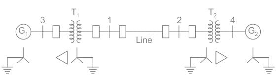 If a double line to ground fault occurs at bus 1, the fault current is _______
- a)4.39 pu
- b)4.67 pu
- c)3.87 pu
- d)4.98 pu
Correct answer is option 'D'. Can you explain this answer?
The reactance data for a power system is shown in the figure in per unit on a common base is as follows.
G1: X1 = X2 = j0.1, X0 = j0.05
G2: X1 = X2 = j0.1, X0 = j0.05
T1: X1 = X2 = j0.25, X0 = j0.25
T2: X1 = X2 = j0.25, X0 = j0.25
Line: X1 = X2 = j0.3, X0 = j0.5
G2: X1 = X2 = j0.1, X0 = j0.05
T1: X1 = X2 = j0.25, X0 = j0.25
T2: X1 = X2 = j0.25, X0 = j0.25
Line: X1 = X2 = j0.3, X0 = j0.5
If a double line to ground fault occurs at bus 1, the fault current is _______
a)
4.39 pu
b)
4.67 pu
c)
3.87 pu
d)
4.98 pu
 | Constructing Careers answered |
For the given power system network, the positive sequence impedance network is given below.
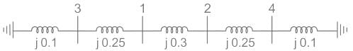
The impedance at a point of fault is,
X1eq = (j0.35)∥(j0.65)
= j0.2275 pu
Negative sequence reactance is the same as positive sequence reactance
X2eq = X1eq = j0.2275pu
The zero sequence reactance network is,
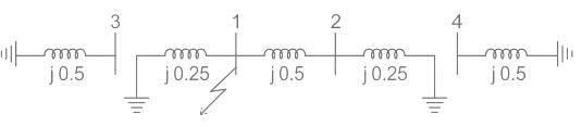
Zero sequence impedance
Z0eq = j0.25 ∥ j0.75 = j0.1875 pu
For a double line to fault at bus 1 is,
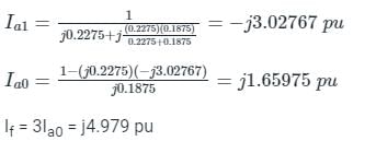
The impedance at a point of fault is,
X1eq = (j0.35)∥(j0.65)
= j0.2275 pu
Negative sequence reactance is the same as positive sequence reactance
X2eq = X1eq = j0.2275pu
The zero sequence reactance network is,
Zero sequence impedance
Z0eq = j0.25 ∥ j0.75 = j0.1875 pu
For a double line to fault at bus 1 is,
Impedance diagram is used for analysis of __________- a)Load flow
- b)Alternator
- c)Fault
- d)Transmission Line
Correct answer is option 'A'. Can you explain this answer?
Impedance diagram is used for analysis of __________
a)
Load flow
b)
Alternator
c)
Fault
d)
Transmission Line
| | Harshad Singh answered |
Impedance diagram is used for analysis of Load flow.
Load flow analysis:
Load flow analysis, also known as power flow analysis, is a fundamental tool used in electrical power systems analysis to determine the steady-state operating conditions of a power system. It involves calculating the voltages, currents, and power flows in a power system under normal operating conditions.
Impedance diagram:
An impedance diagram is a graphical representation of the electrical impedance of a power system. It is a phasor diagram that represents the complex impedance of the various components in the power system, such as generators, transformers, transmission lines, and loads.
Analysis of load flow using impedance diagram:
The impedance diagram is used to analyze the load flow in a power system by considering the complex impedances of the various components. The load flow analysis involves solving a set of nonlinear equations to determine the voltages and currents in the system.
The impedance diagram helps in visualizing the flow of power and reactive power in the system. By analyzing the impedance diagram, engineers can identify areas of high power losses, voltage drops, and reactive power flow. This information is crucial in planning and optimizing the operation of the power system.
The impedance diagram also helps in identifying the voltage stability limits of the system. By analyzing the impedance diagram, engineers can determine the maximum power transfer capability of the system without causing voltage instability.
Benefits of using impedance diagram for load flow analysis:
1. Visual representation: The impedance diagram provides a visual representation of the complex impedances in the power system, making it easier to understand and analyze the load flow.
2. Identification of problem areas: By analyzing the impedance diagram, engineers can identify areas of high power losses, voltage drops, and reactive power flow, helping them to troubleshoot and optimize the system.
3. Voltage stability analysis: The impedance diagram helps in determining the voltage stability limits of the system, ensuring that the system operates within safe limits.
4. Optimization of power system operation: By analyzing the impedance diagram, engineers can optimize the operation of the power system by identifying areas of improvement and implementing corrective measures.
In conclusion, the impedance diagram is a powerful tool used in load flow analysis to analyze the steady-state operating conditions of a power system. It helps in visualizing the flow of power and reactive power, identifying problem areas, and optimizing the operation of the system.
Reactance diagram contains which of the following?- a)Resistance of Alternator
- b)Resistance of transformer winding
- c)Induction motor’s equivalent corcuit
- d)Inductive reactance of transmission lines
Correct answer is option 'D'. Can you explain this answer?
Reactance diagram contains which of the following?
a)
Resistance of Alternator
b)
Resistance of transformer winding
c)
Induction motor’s equivalent corcuit
d)
Inductive reactance of transmission lines
| | Prerna Tiwari answered |
B)Resistance of transformer winding

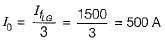
Calculate the per-unit synchronous reactance on the base value of 200 MVA and 20 kV when a 100 MVA with 20 kV synchronous generator has 1pu synchronous reactance.- a)2 pu
- b)4 pu
- c)6 pu
- d)8 pu
Correct answer is option 'A'. Can you explain this answer?
Calculate the per-unit synchronous reactance on the base value of 200 MVA and 20 kV when a 100 MVA with 20 kV synchronous generator has 1pu synchronous reactance.
a)
2 pu
b)
4 pu
c)
6 pu
d)
8 pu
| | Sarthak Yadav answered |
Calculation of Per-Unit Synchronous Reactance:
- Given Base Values:
- S_base = 200 MVA
- V_base = 20 kV
- Given Generator Rating:
- S_gen = 100 MVA
- V_gen = 20 kV
- Xd = 1 pu
Step 1: Calculate the Base Current (I_base):
I_base = S_base / (sqrt(3) * V_base)
I_base = 200 MVA / (sqrt(3) * 20 kV) = 5.7735 kA
Step 2: Calculate the Base Impedance (Z_base):
Z_base = V_base^2 / S_base
Z_base = (20 kV)^2 / 200 MVA = 2 ohms
Step 3: Calculate the Actual Synchronous Reactance (X_d_actual):
X_d_actual = X_d * Z_base
X_d_actual = 1 pu * 2 ohms = 2 ohms
Step 4: Calculate the Per-Unit Synchronous Reactance (X_d_pu):
X_d_pu = X_d_actual / Z_base
X_d_pu = 2 ohms / 2 ohms = 1 pu
Therefore, the per-unit synchronous reactance on the base value of 200 MVA and 20 kV when a 100 MVA with 20 kV synchronous generator has 1 pu synchronous reactance is 2 pu. The correct answer is option 'A'.
A 500 MVA, 11KV synchronous generator has 0.2 p.u. synchronous reactance. The p.u. synchronous reactance on the base values of 100 MVA and 22 KV is- a)0.16
- b)0.01
- c)4.0
- d)0.25
Correct answer is option 'B'. Can you explain this answer?
A 500 MVA, 11KV synchronous generator has 0.2 p.u. synchronous reactance. The p.u. synchronous reactance on the base values of 100 MVA and 22 KV is
a)
0.16
b)
0.01
c)
4.0
d)
0.25
| | Pooja Patel answered |
Concept:
The relation between new per-unit value & old per unit value impedance


Where,
Where,
(Zpu)new = New per unit value of impedance
(Zpu)old = Old per unit value of impedance
kVbase = Old base value of voltage
kVnew = New base value of voltage
MVAnew = New base value of power
MVAold = Old base value of power
Calculation:
Given that,
Xd(old) = 0.2 pu
MVA(new) = 100
MVA(old) = 500
KV(old) = 11
KV(new) = 22
A 50 Hz synchronous generator is initially connected to a long lossless transmission line which is open circuited at the receiving end. With the field voltage held constant, the generator is disconnected from the transmission line. Which of the following may be said about the steady state terminal voltage and field current of the generator?

- a)The magnitude of terminal voltage decreases, and the field current does not change.
- b)The magnitude of terminal voltage increases, and the field current does not change.
- c)The magnitude of terminal voltage increases, and the field current increases.
- d)The magnitude of terminal voltage does not change and the field current decreases.
Correct answer is option 'A'. Can you explain this answer?
A 50 Hz synchronous generator is initially connected to a long lossless transmission line which is open circuited at the receiving end. With the field voltage held constant, the generator is disconnected from the transmission line. Which of the following may be said about the steady state terminal voltage and field current of the generator?
a)
The magnitude of terminal voltage decreases, and the field current does not change.
b)
The magnitude of terminal voltage increases, and the field current does not change.
c)
The magnitude of terminal voltage increases, and the field current increases.
d)
The magnitude of terminal voltage does not change and the field current decreases.
| | Pioneer Academy answered |
A long transmission line under no-load conditions behaves as the capacitive load. The effect of armature current is purely magnetization. When the alternator is disconnected, there is no magnetizing effect. So the terminal voltage decreases with the same field current.
Explanation:
When the generator is connected to an open-circuit transmission line, the line draws a charging current, therefore Vt > Eg.

But, when the generator is disconnected from the line, no charging current is delivered by the generator, i.e.,
But, when the generator is disconnected from the line, no charging current is delivered by the generator, i.e.,
Ic = 0 ⇒ Vt = Eg.
So, the terminal voltage decreases.
The reactance of a generator designated ‘x’ is given as 0.25 pu based on the generator’s name plate rating of 18 kV, 500 MVA. If the base for calculations is changed to 20 kV, 100 MVA, the generator reactance X on new base will be - (in pu)- a)1.025 pu
- b)0.05 pu
- c)0.0405 pu
- d)0.25 pu
Correct answer is option 'C'. Can you explain this answer?
The reactance of a generator designated ‘x’ is given as 0.25 pu based on the generator’s name plate rating of 18 kV, 500 MVA. If the base for calculations is changed to 20 kV, 100 MVA, the generator reactance X on new base will be - (in pu)
a)
1.025 pu
b)
0.05 pu
c)
0.0405 pu
d)
0.25 pu
| | Suyash Joshi answered |
By Xg is a measure of its opposition to the flow of alternating current. It is caused by the inductance and capacitance of the generator's windings and is typically expressed in ohms (Ω). The reactance of a generator is frequency-dependent and can be calculated using the formula Xg = 2πfL - 1/(2πfC), where f is the frequency of the alternating current, L is the inductance of the generator's windings, and C is the capacitance of the generator's windings.
An 11 kV, 25 MVA, 3-phase Y-connected alternator was subjected to three different types of fault at its terminals. The fault currents were:
5610 A for a three phase fault
6760 A for line to line fault
8630 A for single line to ground fault.
If the alternator neutral is solidly grounded, the zero-sequence reactance of the alternator (in pu) is _________
Correct answer is between '0.1,0.15'. Can you explain this answer?
An 11 kV, 25 MVA, 3-phase Y-connected alternator was subjected to three different types of fault at its terminals. The fault currents were:
5610 A for a three phase fault
6760 A for line to line fault
8630 A for single line to ground fault.
If the alternator neutral is solidly grounded, the zero-sequence reactance of the alternator (in pu) is _________
5610 A for a three phase fault
6760 A for line to line fault
8630 A for single line to ground fault.
If the alternator neutral is solidly grounded, the zero-sequence reactance of the alternator (in pu) is _________
| | Ameya Gupta answered |
Solution:
Given data:
Voltage rating of the alternator (V) = 11 kV
Apparent power rating of the alternator (S) = 25 MVA
Fault current for three-phase fault (I3) = 5610 A
Fault current for line to line fault (I2) = 6760 A
Fault current for single line to ground fault (I1) = 8630 A
The alternator neutral is solidly grounded.
Calculating Zero-sequence Reactance:
The zero-sequence reactance of the alternator (X0) can be calculated using the following formula:
X0 = V / (3 * I0)
where I0 is the zero-sequence current.
For a three-phase fault, the zero-sequence current is equal to the phase current, i.e., I0 = I3 / √3.
Substituting the given values in the above formula, we get:
X0 = 11 kV / (3 * 5610 A / √3) = 0.114 pu
For a line to line fault, the zero-sequence current is zero, as there is no current flowing through the neutral. Hence, X0 is undefined for this fault.
For a single line to ground fault, the zero-sequence current is equal to the fault current, i.e., I0 = I1.
Substituting the given values in the above formula, we get:
X0 = 11 kV / (3 * 8630 A) = 0.143 pu
Therefore, the zero-sequence reactance of the alternator is between 0.1 and 0.15 pu, as calculated above.
Conclusion:
In conclusion, the zero-sequence reactance of the alternator can be calculated using the formula X0 = V / (3 * I0), where I0 is the zero-sequence current. For a three-phase fault and a single line to ground fault, the zero-sequence current can be calculated using the given fault current values. However, for a line to line fault, the zero-sequence current is zero, and hence, X0 is undefined.
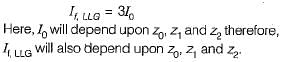
A 30 kV, 50 Hz, 50 MVA generator has the positive, negative, and zero sequence reactance’s of 0.25 pu, 0.15 pu, and 0.05 pu, respectively. The neutral of the generator is grounded with a reactance so that the fault current for a bolted LG fault and that of a bolted three-phase fault at the generator terminal are equal. The value of grounding reactance in ohms (round off to one decimal
Correct answer is between '1.7,1.9'. Can you explain this answer?
A 30 kV, 50 Hz, 50 MVA generator has the positive, negative, and zero sequence reactance’s of 0.25 pu, 0.15 pu, and 0.05 pu, respectively. The neutral of the generator is grounded with a reactance so that the fault current for a bolted LG fault and that of a bolted three-phase fault at the generator terminal are equal. The value of grounding reactance in ohms (round off to one decimal
| | Aaditya Choudhary answered |
Of X1 = 0.15 pu, X2 = 0.25 pu, and X0 = 0.05 pu, respectively. Calculate the short-circuit current at the generator terminals for a three-phase fault at the generator terminals.
Solution:
The short-circuit current can be calculated using the symmetrical component method as follows:
1) Positive sequence current:
I1 = 1/3 * MVA / kV / √3 = 50e6 / 30e3 / √3 = 962.25 A
2) Negative sequence current:
I2 = K * I1 = 0.25 * 962.25 = 240.56 A
3) Zero sequence current:
I0 = K * I1 = 0.05 * 962.25 = 48.11 A
where K = X2 / X1 = 0.25 / 0.15 = 1.67
The total short-circuit current is the vector sum of the three components:
Isc = √(I1^2 + I2^2 + I0^2) = √(962.25^2 + 240.56^2 + 48.11^2) = 996.35 A
Therefore, the short-circuit current at the generator terminals for a three-phase fault is 996.35 A.
On a base of 132 kV, 100 MVA, a transmission line has 0.2 per unit impedance. On a base of 220 kV, 50 MVA, it will have a per unit impedance of:- a)
- b)
- c)
- d)
Correct answer is option 'C'. Can you explain this answer?
On a base of 132 kV, 100 MVA, a transmission line has 0.2 per unit impedance. On a base of 220 kV, 50 MVA, it will have a per unit impedance of:
a)
b)
c)
d)
| | Pioneer Academy answered |
Concept:
Per unit quantity:
Per unit quantity = Actual quantity in the units / Base (or) reference quantity in the same units
⇒ Per unit impedance Zpu = Zactual / Zbase
⇒ Zpu = ZΩ × MVAb / (kVb)2
Conversion of one per unit impedance into another per unit impedance is given by
Calculation:
Given that
Zpu old = 0.2
MVAold = 100 MVA
kVb old = 132 kV
MVAnew = 50 MVA
kVb new = 220 kV
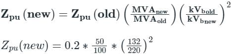
A 30 MV A, 3-phase, 50Hz,13.8kV, star-connected synchronous generator has positive, negative and zero sequence reactances, 15%,15% and 5% respectively. A reactance (Xn) is connected between the neutral of the generator and ground. A double line to ground fault takes place involving phases ′b′and′c′, with a fault impedance of j0.1p.u. The value of Xn (in p.u.) that will limit the positive sequence generator current to 4270 A is _________.
Correct answer is between '1.05,1.15'. Can you explain this answer?
A 30 MV A, 3-phase, 50Hz,13.8kV, star-connected synchronous generator has positive, negative and zero sequence reactances, 15%,15% and 5% respectively. A reactance (Xn) is connected between the neutral of the generator and ground. A double line to ground fault takes place involving phases ′b′and′c′, with a fault impedance of j0.1p.u. The value of Xn (in p.u.) that will limit the positive sequence generator current to 4270 A is _________.
| | Pooja Patel answered |
We have the base current
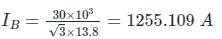
The positive sequence current, Ip = 4270 A
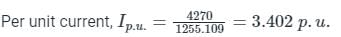
Fault impedance = 0.1 pu
Xn = 3zf + 0.05 + 3xn = 0.35 + 3xn
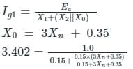
From above equation, we get Xn = 1.07 p.u
The positive sequence current, Ip = 4270 A
Fault impedance = 0.1 pu
Xn = 3zf + 0.05 + 3xn = 0.35 + 3xn
From above equation, we get Xn = 1.07 p.u
The base impedance and base voltage for a given power system are 10Ω and 400 V respectively. The base kVA and the base current will be respectively- a)16000 kVA and 40 A
- b)4 kVA and 16 A
- c)16 kVA and 40 A
- d)4 kVA and 400 A
Correct answer is option 'C'. Can you explain this answer?
The base impedance and base voltage for a given power system are 10Ω and 400 V respectively. The base kVA and the base current will be respectively
a)
16000 kVA and 40 A
b)
4 kVA and 16 A
c)
16 kVA and 40 A
d)
4 kVA and 400 A
| | Maulik Choudhury answered |
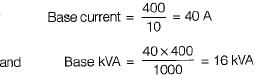
A three-phase star-connected alternator rated at 30 MVA, 13.8 kV has positive, negative, and zero sequence reactance values as 0.25 pu, 0.35 pu, and 0.10 pu respectively. The neutral of the alternator is solidly grounded. Find the current in phase B when a double line to ground fault occurs on its terminals B and C.- a)3.15 pu
- b)2.37 pu
- c)0.68 pu
- d)4.81 pu
Correct answer is option 'D'. Can you explain this answer?
A three-phase star-connected alternator rated at 30 MVA, 13.8 kV has positive, negative, and zero sequence reactance values as 0.25 pu, 0.35 pu, and 0.10 pu respectively. The neutral of the alternator is solidly grounded. Find the current in phase B when a double line to ground fault occurs on its terminals B and C.
a)
3.15 pu
b)
2.37 pu
c)
0.68 pu
d)
4.81 pu
| | Zoya Sharma answered |
The equivalent circuit for LLG fault can be drawn as:
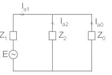
Z1 = j0.25 pu, E = 1 pu
Z2 = j0.35 pu
Z0 = j0.10 pu
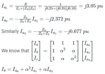
α = 1∠120°
α2 = 1∠-120°
⇒ Ib = 4.804 pu
Z1 = j0.25 pu, E = 1 pu
Z2 = j0.35 pu
Z0 = j0.10 pu
α = 1∠120°
α2 = 1∠-120°
⇒ Ib = 4.804 pu
The positive, negative and zero sequence impedances of a three-phase generator are Z1, Z2 and Z0 respectively. For a line-to-line fault with fault impedance Zf, the fault current is If1 = kIf, where If is the fault current with zero fault impedance. The relation between Zf and k is- a)
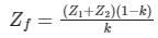
- b)
- c)
- d)
Correct answer is option 'A'. Can you explain this answer?
The positive, negative and zero sequence impedances of a three-phase generator are Z1, Z2 and Z0 respectively. For a line-to-line fault with fault impedance Zf, the fault current is If1 = kIf, where If is the fault current with zero fault impedance. The relation between Zf and k is
a)
b)
c)
d)
| | Pooja Patel answered |
In line to line fault,
fault current with fault impedance zf is
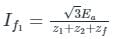
fault current with zero fault impedance is,

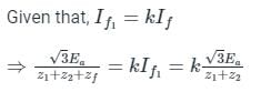
⇒ z1 + z2 = k (z1 + z2 + zf)
⇒ z1 + z2 - k z1 - k z2 = k zf
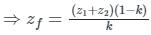
fault current with fault impedance zf is
fault current with zero fault impedance is,
⇒ z1 + z2 = k (z1 + z2 + zf)
⇒ z1 + z2 - k z1 - k z2 = k zf
The pu parameters for a 300 MVA machine on its own base are inertia M = 10 pu and reactance X = 4 pu. The pu values of inertia and reactance on 50 MVA common base, respectively, will be:- a)60, 0.67
- b)40, 0.67
- c)60, 0.4
- d)4, 10
Correct answer is option 'A'. Can you explain this answer?
The pu parameters for a 300 MVA machine on its own base are inertia M = 10 pu and reactance X = 4 pu. The pu values of inertia and reactance on 50 MVA common base, respectively, will be:
a)
60, 0.67
b)
40, 0.67
c)
60, 0.4
d)
4, 10
| | Ishan Saini answered |
Given Data:
- Machine parameters on its own base: Inertia M = 10 pu, Reactance X = 4 pu
- Base MVA of the machine = 300 MVA
- New common base MVA = 50 MVA
Calculations:
Step 1: Calculating the new base values of inertia and reactance
- The new base MVA is 50 MVA, so the new base values of inertia and reactance can be calculated as follows:
- New Inertia = Old Inertia * (Old Base MVA / New Base MVA)
- New Inertia = 10 * (300 / 50) = 60 pu
- New Reactance = Old Reactance * (Old Base MVA / New Base MVA)
- New Reactance = 4 * (300 / 50) = 24 pu
Step 2: Converting the new base values to pu values
- To convert the new base values to pu values, divide them by the new base MVA:
- Inertia on 50 MVA base = 60 / 50 = 1.2 pu
- Reactance on 50 MVA base = 24 / 50 = 0.48 pu
Final Answer:
- The pu values of inertia and reactance on 50 MVA common base are 1.2 pu and 0.48 pu respectively.
Therefore, the correct answer is option A: 60, 0.67.
A transformer is rated at 11 kV/0.4 kV, 500 KVA, 5% reactance. What is the short circuit MVA of the transformer when connected to an infinite bus?- a)20 MVA
- b)10 MVA
- c)15 MVA
- d)5 MVA
Correct answer is option 'B'. Can you explain this answer?
A transformer is rated at 11 kV/0.4 kV, 500 KVA, 5% reactance. What is the short circuit MVA of the transformer when connected to an infinite bus?
a)
20 MVA
b)
10 MVA
c)
15 MVA
d)
5 MVA
| | Pooja Patel answered |
Concept:
Short circuit MVA =
Where,
MVAbase = Full load or base MVA
Xpu = Per unit reactance
Calculation:
Given that, MVAbase = 500 kVA = 0.5 MVA, Xpu= 5% = 0.05
Since the transformer is connected to an infinite bus, the p.u. the reactance of the circuit will be 0.05 i.e., the p.u. reactance offered by the transformer.
∴ short circuit MVA can be calculated as
Short circuit MVA = 0.5/0.05 = 10 MVA
Chapter doubts & questions for Symmetrical and Unsymmetrical Fault Analysis - 6 Months Preparation for GATE Electrical 2026 is part of Electrical Engineering (EE) exam preparation. The chapters have been prepared according to the Electrical Engineering (EE) exam syllabus. The Chapter doubts & questions, notes, tests & MCQs are made for Electrical Engineering (EE) 2026 Exam. Find important definitions, questions, notes, meanings, examples, exercises, MCQs and online tests here.
Chapter doubts & questions of Symmetrical and Unsymmetrical Fault Analysis - 6 Months Preparation for GATE Electrical in English & Hindi are available as part of Electrical Engineering (EE) exam. Download more important topics, notes, lectures and mock test series for Electrical Engineering (EE) Exam by signing up for free.
6 Months Preparation for GATE Electrical675 videos|1390 docs|885 tests |