


All Exams > Electrical Engineering (EE) > 6 Months Preparation for GATE Electrical > All Questions
All questions of DC Machines for Electrical Engineering (EE) Exam
If the DC machine is held constant at 3000 rpm. The DC voltage is 250V and speed is 2950. If the field is held constant with 250V. Is this machine generator or motor?- a)Motor
- b)Generator
- c)None of the mentioned
- d)Any of the mentioned
Correct answer is option 'A'. Can you explain this answer?
If the DC machine is held constant at 3000 rpm. The DC voltage is 250V and speed is 2950. If the field is held constant with 250V. Is this machine generator or motor?
a)
Motor
b)
Generator
c)
None of the mentioned
d)
Any of the mentioned
| | Sravya Khanna answered |
From the speed and emf relation, E = 250*2950/3000
= 245.8 V
This is less than the terminal voltage. Hence it is a motor.
= 245.8 V
This is less than the terminal voltage. Hence it is a motor.

A shunt generator has an induced voltage on open circuit of 127 V. When the machine is on load the terminal voltage is 120 V. The load current if the field resistance be 15 ohm and armature resistance be 15 ohm- a)342 A
- b)350 A
- c)358 A
- d)8 A
Correct answer is option 'A'. Can you explain this answer?
A shunt generator has an induced voltage on open circuit of 127 V. When the machine is on load the terminal voltage is 120 V. The load current if the field resistance be 15 ohm and armature resistance be 15 ohm
a)
342 A
b)
350 A
c)
358 A
d)
8 A
| | Rajeev Menon answered |
Ia*Ra = E-V
= 127 – 120
= 7 V
Ia = 350 A
Ish = 120/15
= 8 A
I = 350 – 8
= 342 A
The voltage drop at brush-commutator contact is variable (1-2V) and dependent of armature current.- a)True
- b)False
Correct answer is option 'B'. Can you explain this answer?
The voltage drop at brush-commutator contact is variable (1-2V) and dependent of armature current.
a)
True
b)
False
 | Sagarika Patel answered |
The voltage drop at brush-commutator contact is variable (1-2V) and independent of armature current.
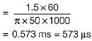
A commutator with a diameter of 50 cm rotates at 1000 rpm. For a brush width of 1.5 cm, the time of commutation is - a)573 μsec
- b)256 msec
- c)625 μsec
- d)448 msec
Correct answer is option 'A'. Can you explain this answer?
A commutator with a diameter of 50 cm rotates at 1000 rpm. For a brush width of 1.5 cm, the time of commutation is
a)
573 μsec
b)
256 msec
c)
625 μsec
d)
448 msec
| | Sanvi Kapoor answered |
Peripheral velocity of commutator is
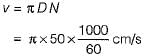
Now, brush width = v x time of commutation
Now, brush width = v x time of commutation
or, time of commutation
The shaft power at the DC Generator is- a)sum of mechanical power and rotational losses
- b)only mechanical losses
- c)no-load losses and mechanical power
- d)any of the mentioned
Correct answer is option 'A'. Can you explain this answer?
The shaft power at the DC Generator is
a)
sum of mechanical power and rotational losses
b)
only mechanical losses
c)
no-load losses and mechanical power
d)
any of the mentioned
 | Swara Dasgupta answered |
Explanation: The shaft power is sum of mechanical power and rotational losses.
correct answer is option A
Inspite of heavy initial investments, dc motors are used due to- a)flexibility and ease of control
- b)lower losses
- c)improved power factor of the system
- d)all of the mentioned
Correct answer is option 'A'. Can you explain this answer?
Inspite of heavy initial investments, dc motors are used due to
a)
flexibility and ease of control
b)
lower losses
c)
improved power factor of the system
d)
all of the mentioned
| | Arya Mukherjee answered |
The control of dc machines is very much simplified when compared to other machines. So this makes it very useful when compared.
The manufacturer has mentioned a medium starting torque and 15% speed regulation. The most appropriate motor for his requirement is- a)dc shunt motor
- b)induction motor
- c)differential motor
- d)none of the mentioned
Correct answer is option 'A'. Can you explain this answer?
The manufacturer has mentioned a medium starting torque and 15% speed regulation. The most appropriate motor for his requirement is
a)
dc shunt motor
b)
induction motor
c)
differential motor
d)
none of the mentioned
| | Uday Saini answered |
The dc shunt motor provides a medium values of the torque.
Centrifugal pumps, fans-blowers use- a)shunt as well as induction motor
- b)only shunt motors
- c)only induction motor
- d)none of the mentioned
Correct answer is option 'A'. Can you explain this answer?
Centrifugal pumps, fans-blowers use
a)
shunt as well as induction motor
b)
only shunt motors
c)
only induction motor
d)
none of the mentioned
| | Yash Patel answered |
Centrifugal pumps, fans-blowers use shunt as well as induction motor.
Mark the possible causes of overheating of commutator in a DC machine.- a)Any of the mentioned
- b)Restricted ventilation
- c)Shorted winding
- d)Overload
Correct answer is option 'A'. Can you explain this answer?
Mark the possible causes of overheating of commutator in a DC machine.
a)
Any of the mentioned
b)
Restricted ventilation
c)
Shorted winding
d)
Overload
| | Lavanya Menon answered |
All the factors can cause the overheating of commutator.
In the hopkinson’s test on two DC machines. Machine A has field current of 1.4A and B has field current of 1.3A. Which machine acts as motor?- a)B
- b)A
- c)A,B
- d)None of the mentioned
Correct answer is option 'A'. Can you explain this answer?
In the hopkinson’s test on two DC machines. Machine A has field current of 1.4A and B has field current of 1.3A. Which machine acts as motor?
a)
B
b)
A
c)
A,B
d)
None of the mentioned
| | Sushant Mukherjee answered |
Correct answer is option A.
Ea/Eb = 1.4/1.3
Ea= 1.077 Eb > Eb
So, the machine will act as motor.
Ea/Eb = 1.4/1.3
Ea= 1.077 Eb > Eb
So, the machine will act as motor.
Which of the following are applied with differential compound motor?- a)Hoist
- b)Cranes
- c)Drilling machines
- d)None of the mentioned
Correct answer is option 'A'. Can you explain this answer?
Which of the following are applied with differential compound motor?
a)
Hoist
b)
Cranes
c)
Drilling machines
d)
None of the mentioned
| | Mahesh Singh answered |
Practically it is never used as the speed can rise very high.
If the electromagnetic torque in a DC shunt-generator is opposite, what can be further concluded?- a)Mechanical power is absorbed by the machine
- b)Mechanical power is delivered by the machine
- c)Electromagnetic torque is in same direction of prime mover
- d)None of the mentioned
Correct answer is option 'A'. Can you explain this answer?
If the electromagnetic torque in a DC shunt-generator is opposite, what can be further concluded?
a)
Mechanical power is absorbed by the machine
b)
Mechanical power is delivered by the machine
c)
Electromagnetic torque is in same direction of prime mover
d)
None of the mentioned
| | Kajal Mukherjee answered |
Introduction:
In a DC shunt-generator, the electromagnetic torque is generated due to the interaction between the magnetic field produced by the field winding and the armature current. This torque is responsible for converting electrical energy into mechanical energy.
Explanation:
When the electromagnetic torque in a DC shunt-generator is opposite, it means that the direction of the torque is opposite to the direction of rotation. This situation indicates that the mechanical power is being absorbed by the machine rather than being delivered.
Reasoning:
To understand why the correct answer is option 'A' (Mechanical power is absorbed by the machine), let's consider the basic principle of operation of a DC shunt-generator.
- A DC shunt-generator consists of a field winding and an armature winding.
- When the field winding is excited with a direct current, it creates a magnetic field in the machine.
- The armature winding is connected to an external mechanical prime mover, such as a turbine or an engine.
- When the armature winding is supplied with a direct current, it produces an armature flux.
- The interaction between the field flux and the armature flux generates an electromagnetic torque.
- This torque causes the armature to rotate, converting electrical energy into mechanical energy.
Now, if the electromagnetic torque is opposite, it means that the torque is acting against the rotation of the machine. This implies that the prime mover has to exert more mechanical power to overcome the opposing torque and keep the machine running.
Since the prime mover is exerting more mechanical power, it indicates that the machine is absorbing mechanical power instead of delivering it. In other words, the machine is acting as a load or a consumer of mechanical power rather than a source of mechanical power.
Conclusion:
Therefore, when the electromagnetic torque in a DC shunt-generator is opposite, it can be concluded that the machine is absorbing mechanical power. This implies that the machine is acting as a load rather than a generator, and the prime mover has to supply additional power to keep the machine running.
The main concern before doing hopkinson’s test for finding efficiency is- a)needs one motor and one generator is that it
- b)ignores iron and stray losses
- c)needs one motor
- d)requires identical shunt machines
Correct answer is option 'D'. Can you explain this answer?
The main concern before doing hopkinson’s test for finding efficiency is
a)
needs one motor and one generator is that it
b)
ignores iron and stray losses
c)
needs one motor
d)
requires identical shunt machines
| | Samridhi Bose answered |
It is must that both the machines are identical as required by the calculations.
Most commercial compound dc generator are normally supplied by manufacturers as ______ compounded machines.- a)over
- b)under
- c)level
- d)none of the mentioned
Correct answer is option 'A'. Can you explain this answer?
Most commercial compound dc generator are normally supplied by manufacturers as ______ compounded machines.
a)
over
b)
under
c)
level
d)
none of the mentioned
| | Raghav Nambiar answered |
Most commercial compound dc generator are normally supplied by manufacturers as over compounded.
The most appropriate relation to find efficiency of the generator- a)output/(output + losses)
- b)(output – losses)/input
- c)(output – losses)/(output + losses)
- d)any of the mentioned
Correct answer is option 'A'. Can you explain this answer?
The most appropriate relation to find efficiency of the generator
a)
output/(output + losses)
b)
(output – losses)/input
c)
(output – losses)/(output + losses)
d)
any of the mentioned
| | Dhruv Datta answered |
For a generator the output can be measured and so this expression is used
If the torque is in the direction of rotation, the DC machine acts as- a)generator
- b)motor
- c)amplidyne
- d)any of the mentioned
Correct answer is option 'A'. Can you explain this answer?
If the torque is in the direction of rotation, the DC machine acts as
a)
generator
b)
motor
c)
amplidyne
d)
any of the mentioned
| | Jaya Datta answered |
The electromagnetic torque generated in the dc generator is in the direction in which the prime mover is rotated.It is produced due to the action of armature current and stator field.
The quantities needed to complete retardation test are/is- a)dw/dt and moment of inertia
- b)dw/dt
- c)current
- d)any of the mentioned
Correct answer is option 'A'. Can you explain this answer?
The quantities needed to complete retardation test are/is
a)
dw/dt and moment of inertia
b)
dw/dt
c)
current
d)
any of the mentioned
| | Parth Ghoshal answered |
We need the angular acceleration and the moment of inertia of the machine.
Hoists, cranes and battery powered vehicles use _________ motors in the locomotive.- a)dc series
- b)dc shunt
- c)induction
- d)reluctance
Correct answer is option 'A'. Can you explain this answer?
Hoists, cranes and battery powered vehicles use _________ motors in the locomotive.
a)
dc series
b)
dc shunt
c)
induction
d)
reluctance
| | Gitanjali Deshpande answered |
Hoists, cranes require large starting torque which can be provided by dc series motor.
LAP winding is employed in a dc machine of- a)high current and low voltage rating
- b)low current and high voltage rating
- c)high current and high voltage rating
- d)low current and low voltage rating
Correct answer is option 'A'. Can you explain this answer?
LAP winding is employed in a dc machine of
a)
high current and low voltage rating
b)
low current and high voltage rating
c)
high current and high voltage rating
d)
low current and low voltage rating
| | Malavika Nair answered |
For LAP winding, number of parallel path = number of poles.
Thus, resistance is less compared to wave winding. Hence, current rating is more and voltage rating is less compared to wave winding.
Thus, resistance is less compared to wave winding. Hence, current rating is more and voltage rating is less compared to wave winding.
Consider a 200V, 25kW, 30A DC machine lap connected with armature resistance of 0.4 ohms. If the machine is later wave wound, then the developed power is- a)25 kW
- b)12.5 kW
- c)20 kW
- d)50 kW
Correct answer is option 'A'. Can you explain this answer?
Consider a 200V, 25kW, 30A DC machine lap connected with armature resistance of 0.4 ohms. If the machine is later wave wound, then the developed power is
a)
25 kW
b)
12.5 kW
c)
20 kW
d)
50 kW
| | Prisha Sen answered |
The power of the machine remains unaltered by the type of connections.
The efficiency in the swineburne’s test can be found.- a)True
- b)False
Correct answer is option 'A'. Can you explain this answer?
The efficiency in the swineburne’s test can be found.
a)
True
b)
False
| | Sanchita Sharma answered |
Because the constant losses are known.
A 24 kW, 250 V, 1600 rpm separately-excited d.c. generator has armature circuit resistance of 0.1Ω. The machine is first run at rated speed and the field winding current is adjusted to give an open circuit voltage of 260 V. Now, when the generator is loaded to deliver its rated current, the speed of the driving motor is found to be 1500 r.p.m. Assuming flux to remain constant, the terminal voltage of the generator under these conditions is- a)250 volt
- b)226 volt
- c)238 volt
- d)234 volt
Correct answer is option 'D'. Can you explain this answer?
A 24 kW, 250 V, 1600 rpm separately-excited d.c. generator has armature circuit resistance of 0.1Ω. The machine is first run at rated speed and the field winding current is adjusted to give an open circuit voltage of 260 V. Now, when the generator is loaded to deliver its rated current, the speed of the driving motor is found to be 1500 r.p.m. Assuming flux to remain constant, the terminal voltage of the generator under these conditions is
a)
250 volt
b)
226 volt
c)
238 volt
d)
234 volt
| | Kajal Mukherjee answered |
We know that,
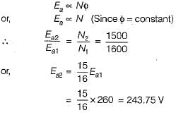
Now, rated armature current is
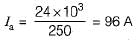
So, the terminal voltage is
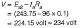
Now, rated armature current is
So, the terminal voltage is
The conductor EMF and current are in _____ direction and developed torque is in _____ for generating mode.- a)same, opposite
- b)same,same
- c)opposite, same
- d)opposite, opposite
Correct answer is option 'A'. Can you explain this answer?
The conductor EMF and current are in _____ direction and developed torque is in _____ for generating mode.
a)
same, opposite
b)
same,same
c)
opposite, same
d)
opposite, opposite
| | Arshiya Basu answered |
The conductor emf and current will be in same direction and the developed torque is in opposite direction for a generator.
A 200 V dc motor has external resistances of Ra and Rf in armature and field circuits respectively. The starting current is reduced when- a)Ra is maximum and Rf minimum
- b)Rf is maximum and Ra minimum
- c)Ra is minimum and Rf minimum
- d)Ra is maximum and Rf maximum
Correct answer is option 'A'. Can you explain this answer?
A 200 V dc motor has external resistances of Ra and Rf in armature and field circuits respectively. The starting current is reduced when
a)
Ra is maximum and Rf minimum
b)
Rf is maximum and Ra minimum
c)
Ra is minimum and Rf minimum
d)
Ra is maximum and Rf maximum
| | Sanjana Chopra answered |
When Ra is maximum and Rf minimum then the current to the armature is reduced. And hence the sparkings are reduced while starting.
The possible assumption is/are made while doing swineburne’s test
(i) mechanical loss constant
(ii) Armature reaction neglected
(iii) Increase- a)(i) and (ii)
- b)(iii) and (i)
- c)(i), (ii), and (iii)
- d)(i)
Correct answer is option 'A'. Can you explain this answer?
The possible assumption is/are made while doing swineburne’s test
(i) mechanical loss constant
(ii) Armature reaction neglected
(iii) Increase
(i) mechanical loss constant
(ii) Armature reaction neglected
(iii) Increase
a)
(i) and (ii)
b)
(iii) and (i)
c)
(i), (ii), and (iii)
d)
(i)
| | Rajesh Kumar answered |
There is decrease in flux due to positive temperature coefficient of resistance in shunt machine.
DC Motor torque depends on- a)geometry
- b)magnetic properties
- c)any of the mentioned
- d)both geometry and magnetic properties of the structure
Correct answer is option 'D'. Can you explain this answer?
DC Motor torque depends on
a)
geometry
b)
magnetic properties
c)
any of the mentioned
d)
both geometry and magnetic properties of the structure
| | Pranjal Datta answered |
The torque will indeed depend on the geometry as well the magnetic materials used in the construction of the dc machine. Though this remains constant with the machine.
A d.c. generator has been provided tappings on the armature winding at intervals of 120 degrees from the side of commutator. The connection will be- a)delta connected alternator
- b)star connected alternator
- c)star connected induction motor
- d)any of the mentioned
Correct answer is option 'A'. Can you explain this answer?
A d.c. generator has been provided tappings on the armature winding at intervals of 120 degrees from the side of commutator. The connection will be
a)
delta connected alternator
b)
star connected alternator
c)
star connected induction motor
d)
any of the mentioned
| | Dipanjan Nambiar answered |
Dc generator if has displaced by 120 degrees physically then it will be act as ac machine.
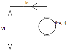
The circuit depicting the equation V=Ea + I*Ra.- a)
- b)
- c)
- d)
Correct answer is option 'A'. Can you explain this answer?
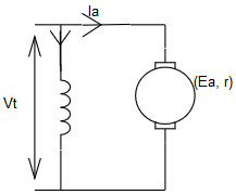
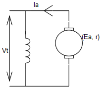
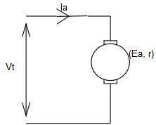
The circuit depicting the equation V=Ea + I*Ra.
a)
b)
c)
d)
| | Ameya Nambiar answered |
This is a motor performance equation.
Long back ago, magnetic casette were in use, having permanent magnet dc motors which had- a)magnets on stator and armature on rotor
- b)magnet on rotor and armature on stator
- c)electronic commutation
- d)all of the mentioned
Correct answer is option 'A'. Can you explain this answer?
Long back ago, magnetic casette were in use, having permanent magnet dc motors which had
a)
magnets on stator and armature on rotor
b)
magnet on rotor and armature on stator
c)
electronic commutation
d)
all of the mentioned
| | Aaditya Choudhary answered |
PMDC motors have field fixed on the stator and rotor has coils.
If the torque induced is zero in the dc machine, it can be said that- a)current is zero
- b)flux can be zero
- c)current or flux=0
- d)any of the mentioned
Correct answer is option 'A'. Can you explain this answer?
If the torque induced is zero in the dc machine, it can be said that
a)
current is zero
b)
flux can be zero
c)
current or flux=0
d)
any of the mentioned
 | Harsh B answered |
The torque at steady state of operation is zero as the emf induced is equal to the source voltage. Also the the very much starting the current will be zero which will not let the emf to get induced.
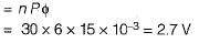
A 6-pole DC machine with lap winding has 300 conductors and a flux per pole of 15 mWb. If the machine is driven at 1800 rpm, then the average EMF induced per conductor will be:- a)3.6 V
- b)2.7 V
- c)9 V
- d)162 V
Correct answer is option 'B'. Can you explain this answer?
A 6-pole DC machine with lap winding has 300 conductors and a flux per pole of 15 mWb. If the machine is driven at 1800 rpm, then the average EMF induced per conductor will be:
a)
3.6 V
b)
2.7 V
c)
9 V
d)
162 V
 | Gate Gurus answered |
Given, speed,
N= 1800 rpm
n = 1800/60 rps = 30 rps
Average emf induced per conductor
N= 1800 rpm
n = 1800/60 rps = 30 rps
Average emf induced per conductor
Swineburne’s test is applicable to those machines in which flux is practically _______- a)constant
- b)linear
- c)non-linear
- d)none of the mentioned
Correct answer is option 'A'. Can you explain this answer?
Swineburne’s test is applicable to those machines in which flux is practically _______
a)
constant
b)
linear
c)
non-linear
d)
none of the mentioned
| | Anshika Khanna answered |
Because the constant losses are known in advance of the test is conducted.
The torque induced beyond the pole shoes in the DC machine is- a)0
- b)2/pi *phi *i
- c)4/pi *phi *i
- d)none of the mentioned
Correct answer is option 'A'. Can you explain this answer?
The torque induced beyond the pole shoes in the DC machine is
a)
0
b)
2/pi *phi *i
c)
4/pi *phi *i
d)
none of the mentioned
| | Sharmila Kulkarni answered |
The magnetic field vanishes at the pole terminals and thus the cross product with the magnetic field yields zero.
______ test is used for determining the efficiency of a traction motor- a)Field
- b)Retardation
- c)Hopkinson
- d)Swineburne’s
Correct answer is option 'A'. Can you explain this answer?
______ test is used for determining the efficiency of a traction motor
a)
Field
b)
Retardation
c)
Hopkinson
d)
Swineburne’s
| | Prasenjit Yadav answered |
Field test is used for finding efficiency of a traction motor.
Interpoles are used to start the dc motor above the base speed.- a)True
- b)False
Correct answer is option 'B'. Can you explain this answer?
Interpoles are used to start the dc motor above the base speed.
a)
True
b)
False
| | Manoj Chaudhary answered |
Interpoles do not reduce the flux across the windings, hence the speed does not rise above base speed.
The simple rotating loop between pole faces connected to a battery and resistor through a switch, the specifications of this machine are radius = 0.5m, length 1m, resistance = 0.3 ohms and magnitude strength = 0.25T is supplied with 120V. What is the steady state angular velocity at no-load?- a)480 rad/s
- b)960 rad/s
- c)320 rad/s
- d)490 rad/s
Correct answer is option 'A'. Can you explain this answer?
The simple rotating loop between pole faces connected to a battery and resistor through a switch, the specifications of this machine are radius = 0.5m, length 1m, resistance = 0.3 ohms and magnitude strength = 0.25T is supplied with 120V. What is the steady state angular velocity at no-load?
a)
480 rad/s
b)
960 rad/s
c)
320 rad/s
d)
490 rad/s
| | Aman Jain answered |
v = V/(2*r*l*B)
= 120/(2*0.0005*1*0.25)
= 480 rad/s.
= 120/(2*0.0005*1*0.25)
= 480 rad/s.
Most commercial compound dc generator are normally supplied by manufacturers as over compound machines because- a)degree of compounding can be adjusted by diverters acrosss series field
- b)they have ideally best for HVDC
- c)cost effective than shunt
- d)zero percent regulation
Correct answer is option 'A'. Can you explain this answer?
Most commercial compound dc generator are normally supplied by manufacturers as over compound machines because
a)
degree of compounding can be adjusted by diverters acrosss series field
b)
they have ideally best for HVDC
c)
cost effective than shunt
d)
zero percent regulation
| | Abhay Khanna answered |
It is usually over compounded so that degree of compounding can be adjusted by diverters across series field.
Maximum torque in dc series motor is limited by- a)commutation
- b)heating
- c)field control
- d)all of the mentioned
Correct answer is option 'A'. Can you explain this answer?
Maximum torque in dc series motor is limited by
a)
commutation
b)
heating
c)
field control
d)
all of the mentioned
 | Shivam Sharma answered |
Commutation is the process which reduces the induced emf and so the torque.
Assertion (A): Armature resistance control method of speed control of dc motors is wasteful and inefficient.
Reason (R): Large amount of power is wasted in the control resistances, specially in case of shunt motors'.- a)Both A and R are true and R is a correct explanation of A.
- b)Both A and R are true but R is not a correct explanation of A.
- c)A is true but R is false.
- d)A is false but R is true.
Correct answer is option 'A'. Can you explain this answer?
Assertion (A): Armature resistance control method of speed control of dc motors is wasteful and inefficient.
Reason (R): Large amount of power is wasted in the control resistances, specially in case of shunt motors'.
Reason (R): Large amount of power is wasted in the control resistances, specially in case of shunt motors'.
a)
Both A and R are true and R is a correct explanation of A.
b)
Both A and R are true but R is not a correct explanation of A.
c)
A is true but R is false.
d)
A is false but R is true.
| | Dipanjan Nambiar answered |
Assertion (A): Armature resistance control method of speed control of DC motors is wasteful and inefficient.
Reason (R): Large amount of power is wasted in the control resistances, specially in case of shunt motors.
Explanation:
The given assertion and reason state that the armature resistance control method of speed control of DC motors is wasteful and inefficient because a large amount of power is wasted in the control resistances, especially in the case of shunt motors. Let's analyze this statement in detail.
Armature Resistance Control Method:
In the armature resistance control method, the speed of a DC motor is controlled by varying the armature resistance. This is achieved by inserting a variable resistance in series with the armature winding. By changing the resistance, the voltage drop across the armature winding is varied, which in turn affects the motor speed.
Power Loss in Control Resistances:
The control resistances used in the armature resistance control method cause a significant power loss. This power loss happens due to the voltage drop across the resistance and the current flowing through it. The power loss can be calculated using the formula: Power Loss = Voltage Drop * Current.
Shunt Motors:
Shunt motors are a type of DC motors where the field winding is connected in parallel (shunt) with the armature winding. In shunt motors, the armature resistance control method is commonly used for speed control.
Explanation of Assertion and Reason:
The assertion states that the armature resistance control method is wasteful and inefficient. This is because a large amount of power is wasted in the control resistances. The reason provided further explains that this wastage of power is particularly significant in the case of shunt motors.
The armature resistance control method causes power loss due to the voltage drop across the control resistances. This power loss is undesirable as it reduces the overall efficiency of the motor and leads to wastage of energy. In the case of shunt motors, where the armature resistance control method is commonly used, the power loss can be even higher.
Conclusion:
Based on the above explanation, both the assertion and reason are true, and the reason correctly explains the assertion. The armature resistance control method of speed control of DC motors is indeed wasteful and inefficient due to the power loss in the control resistances, especially in the case of shunt motors.
The cogging torque is absent in the permanent magnet dc machine is due to- a)non-magnetic nature of rotor
- b)magnetic nature of rotor
- c)absence of ac supply
- d)any of the mentioned
Correct answer is option 'A'. Can you explain this answer?
The cogging torque is absent in the permanent magnet dc machine is due to
a)
non-magnetic nature of rotor
b)
magnetic nature of rotor
c)
absence of ac supply
d)
any of the mentioned
| | Rahul Chakraborty answered |
It is due to the fact that no field poles are induced in PMDC to create magnetic flux leading to harmonics.
Similarity between Hopkinonson’s and field’s test is that- a)both need 2 similar mechanically coupled motors
- b)both need similar electrically coupled motor
- c)regenerative power
- d)negligible power
Correct answer is option 'A'. Can you explain this answer?
Similarity between Hopkinonson’s and field’s test is that
a)
both need 2 similar mechanically coupled motors
b)
both need similar electrically coupled motor
c)
regenerative power
d)
negligible power
| | Dhruv Datta answered |
The machines have to be mechanically coupled together.
The simple rotating loop between pole faces connected to a battery and resistor through a switch, the specifications of this machine are radius = 0.5m, length 1m, resistance = 0.3 ohms and magnitude strength = 0.25T is supplied with 120V. Suddenly the switch is closed at t=0, what is observed in the circuit?- a)Current will flow but zero induced EMF
- b)Current will not flow and zero induced EMF
- c)Current will not flow but EMF is induced
- d)Current will flow and EMF will also be induced
Correct answer is option 'A'. Can you explain this answer?
The simple rotating loop between pole faces connected to a battery and resistor through a switch, the specifications of this machine are radius = 0.5m, length 1m, resistance = 0.3 ohms and magnitude strength = 0.25T is supplied with 120V. Suddenly the switch is closed at t=0, what is observed in the circuit?
a)
Current will flow but zero induced EMF
b)
Current will not flow and zero induced EMF
c)
Current will not flow but EMF is induced
d)
Current will flow and EMF will also be induced
| | Divya Nair answered |
Introduction:
The given circuit consists of a rotating loop between pole faces that is connected to a battery and resistor through a switch. The specifications of the machine are as follows: radius = 0.5m, length = 1m, resistance = 0.3 ohms, and magnetic field strength = 0.25T. The machine is supplied with 120V. The switch is closed at t=0 and we need to determine what is observed in the circuit.
Explanation:
When the switch is closed, the circuit is completed and a current starts to flow through the loop. Let's analyze the different aspects of the circuit to understand the observed behavior.
Magnetic Field and Loop:
The magnetic field strength is given as 0.25T. When the loop rotates, it cuts through the magnetic field lines and induces an electromotive force (EMF) in the loop. This phenomenon is known as electromagnetic induction.
EMF Induced:
As the loop rotates, the flux through the loop changes, resulting in an induced EMF. According to Faraday's Law of electromagnetic induction, the magnitude of the induced EMF is given by the equation:
EMF = -N * dΦ/dt
Where EMF is the induced electromotive force, N is the number of turns in the loop, and dΦ/dt is the rate of change of magnetic flux through the loop. In this case, since the loop has only one turn, the equation simplifies to:
EMF = -dΦ/dt
As the switch is closed at t=0, the rate of change of magnetic flux is initially zero. Therefore, the induced EMF at t=0 is also zero.
Current Flow:
The battery connected to the circuit provides a potential difference of 120V. As per Ohm's Law, the current flowing through the circuit is given by the equation:
I = V/R
Where I is the current, V is the potential difference, and R is the resistance. Substituting the given values, we get:
I = 120V / 0.3Ω
I = 400A
Therefore, a current of 400A flows through the circuit.
Conclusion:
Based on the analysis, we can conclude that when the switch is closed at t=0, a current will flow through the circuit but there will be zero induced EMF at that instant. Hence, the correct answer is option 'A': Current will flow but zero induced EMF.
For a universal motor, the rated supply current is 10A giving a rated torque of 100 N-m. If a current of 5A is applied, what will be generated torque vary to?- a)250 N-m
- b)400 N-m
- c)500 N-m
- d)1000 N-m
Correct answer is option 'B'. Can you explain this answer?
For a universal motor, the rated supply current is 10A giving a rated torque of 100 N-m. If a current of 5A is applied, what will be generated torque vary to?
a)
250 N-m
b)
400 N-m
c)
500 N-m
d)
1000 N-m
| | Bibek Saha answered |
The torque is proportional to the square of the current.
So the new torque will be 100*(2^2)= 400 N-m.
So the new torque will be 100*(2^2)= 400 N-m.
Retardation test on DC shunt motor is used for finding _______- a)stray losses
- b)copper losses
- c)friction losses
- d)iron losses
Correct answer is option 'A'. Can you explain this answer?
Retardation test on DC shunt motor is used for finding _______
a)
stray losses
b)
copper losses
c)
friction losses
d)
iron losses
| | Ritika Sarkar answered |
Retardation test is used for finding the stray losses.
Consider the following statements about the field windings used for various types of dc machines:
1. For dc shunt machines, large number of turns of small cross-section are used.
2. For dc series machine, small number of turns of large cross-section are used.
3. For dc compound machine, both shunt (thick wire) and series (thin wire) field windings are used.
Out of the above statements the correct statements is/are:- a)3 only
- b)1,2 and 3
- c)1 and 2 only
- d)None of these
Correct answer is option 'C'. Can you explain this answer?
Consider the following statements about the field windings used for various types of dc machines:
1. For dc shunt machines, large number of turns of small cross-section are used.
2. For dc series machine, small number of turns of large cross-section are used.
3. For dc compound machine, both shunt (thick wire) and series (thin wire) field windings are used.
Out of the above statements the correct statements is/are:
a)
3 only
b)
1,2 and 3
c)
1 and 2 only
d)
None of these
| | Gargi Mishra answered |
For dc shunt machine, field current is very less, therefore for required field AT/Pole, number of turns of field winding is increased. Thus, R should be high for low If.
For dc series machine field winding current is equal to armature current which is of larger value. Therefore, number of turns of field winding is reduced to get the required field AT/Pole. As it has to handle large current, therefore resistance of field winding should be less by keeping the winding thick. Statement-3 is wrong.
For dc series machine field winding current is equal to armature current which is of larger value. Therefore, number of turns of field winding is reduced to get the required field AT/Pole. As it has to handle large current, therefore resistance of field winding should be less by keeping the winding thick. Statement-3 is wrong.
A dc motor is connected in the short-shunt configuration, but the series and the shunt windings get interchanged by mistake and the motor is connected to the rated voltage,- a)neither of the windings get short-circuit
- b)series winding gets overloaded
- c)shunt winding gets overloaded
- d)both of the winding get overloaded
Correct answer is option 'A'. Can you explain this answer?
A dc motor is connected in the short-shunt configuration, but the series and the shunt windings get interchanged by mistake and the motor is connected to the rated voltage,
a)
neither of the windings get short-circuit
b)
series winding gets overloaded
c)
shunt winding gets overloaded
d)
both of the winding get overloaded
| | Aditya Deshmukh answered |
In the short shunt configuration, the winding interchanging does not change the configuration of the set up so none of the winding get affected.
Assertion (A): DC series motors are suitable for buses, trolleys, hoists and trains.
Reason (R): DC series motors are variable Speed motors.- a)Both A and R are true and R is a correct explanation of A,
- b)Both A and R are true but R is not a correct explanation of A.
- c)A is true but R is false.
- d)A is false but R is true.
Correct answer is option 'B'. Can you explain this answer?
Assertion (A): DC series motors are suitable for buses, trolleys, hoists and trains.
Reason (R): DC series motors are variable Speed motors.
Reason (R): DC series motors are variable Speed motors.
a)
Both A and R are true and R is a correct explanation of A,
b)
Both A and R are true but R is not a correct explanation of A.
c)
A is true but R is false.
d)
A is false but R is true.
| | Prisha Sengupta answered |
The reason of assertion is that dc series motor develop high torque at start due to which these motors are used for hard to start loads. Reason is also correct because these are variable speed motors.
Hopkinson’s test is also called regenerative test due to- a)energy of one machine is used to drive other
- b)feedback
- c)losses are least
- d)extra motor is used
Correct answer is option 'A'. Can you explain this answer?
Hopkinson’s test is also called regenerative test due to
a)
energy of one machine is used to drive other
b)
feedback
c)
losses are least
d)
extra motor is used
| | Aditya Basu answered |
Regenerative phenomena utilizes the energy of the running machine to tap the dynamically produced energy and use it to charge the battery.
If the armature terminal voltage is more that its induced EMF, the DC machine given is- a)motoring mode
- b)generating mode
- c)regenerative mode
- d)none of the mentioned
Correct answer is option 'A'. Can you explain this answer?
If the armature terminal voltage is more that its induced EMF, the DC machine given is
a)
motoring mode
b)
generating mode
c)
regenerative mode
d)
none of the mentioned
| | Vaishnavi Nair answered |
As the terminal voltage is lesser than armature voltage, the supply is fed to the machine and so it will be acting like a motor.
In the Hopkinson’s test on two DC machines. Machine A has field current of 1.4A and B has field current of 1.3A. Which machine acts as generator?- a)B
- b)A
- c)A,B
- d)None of the mentioned
Correct answer is option 'B'. Can you explain this answer?
In the Hopkinson’s test on two DC machines. Machine A has field current of 1.4A and B has field current of 1.3A. Which machine acts as generator?
a)
B
b)
A
c)
A,B
d)
None of the mentioned
| | Nikhil Iyer answered |
Ea/Eb = 1.4/1.3
Ea= 1.077 Eb > Eb
So, the machine will act as generator.
Ea= 1.077 Eb > Eb
So, the machine will act as generator.
Chapter doubts & questions for DC Machines - 6 Months Preparation for GATE Electrical 2026 is part of Electrical Engineering (EE) exam preparation. The chapters have been prepared according to the Electrical Engineering (EE) exam syllabus. The Chapter doubts & questions, notes, tests & MCQs are made for Electrical Engineering (EE) 2026 Exam. Find important definitions, questions, notes, meanings, examples, exercises, MCQs and online tests here.
Chapter doubts & questions of DC Machines - 6 Months Preparation for GATE Electrical in English & Hindi are available as part of Electrical Engineering (EE) exam. Download more important topics, notes, lectures and mock test series for Electrical Engineering (EE) Exam by signing up for free.
6 Months Preparation for GATE Electrical675 videos|1390 docs|885 tests |