


All Exams >
Electronics and Communication Engineering (ECE) >
Communication System >
All Questions
All questions of Amplitude Modulation: Analog Communication for Electronics and Communication Engineering (ECE) Exam
What is the carrier frequency in an AM wave when its highest frequency component is 850Hz and the bandwidth of the signal is 50Hz?- a)80 Hz
- b)695 Hz
- c)625 Hz
- d)825 Hz
Correct answer is option 'D'. Can you explain this answer?
What is the carrier frequency in an AM wave when its highest frequency component is 850Hz and the bandwidth of the signal is 50Hz?
a)
80 Hz
b)
695 Hz
c)
625 Hz
d)
825 Hz
|
|
Sarita Yadav answered |
Upper frequency = 850Hz
Bandwidth = 50Hz
Therefore lower Frequency = 850 - 50= 800 Hz
Carrier Frequency = (850-800)/2
= 825 Hz
Bandwidth = 50Hz
Therefore lower Frequency = 850 - 50= 800 Hz
Carrier Frequency = (850-800)/2
= 825 Hz

A 10 kW carrier is sinusoidally modulated by two carriers corresponding to a modulation index of 30% and 40% respectively. The total radiated power(is- a)11.25 kW
- b)12.5 kW
- c)15 kW
- d)17 kW
Correct answer is option 'A'. Can you explain this answer?
A 10 kW carrier is sinusoidally modulated by two carriers corresponding to a modulation index of 30% and 40% respectively. The total radiated power(is
a)
11.25 kW
b)
12.5 kW
c)
15 kW
d)
17 kW

|
Baishali Bajaj answered |
The required answer is 1 (1 + 0.42 + 0.32) or 11.25 kW.
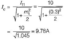
The antenna current of an AM transmitter is 10 A when it is modulated to depth of 30% by an audio signal. It increases to 11 A when another signal modulates the carrier signal. The modulation index due to second signal is- a)62%
- b)66%
- c)67%
- d)64%
Correct answer is option 'B'. Can you explain this answer?
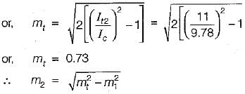
The antenna current of an AM transmitter is 10 A when it is modulated to depth of 30% by an audio signal. It increases to 11 A when another signal modulates the carrier signal. The modulation index due to second signal is
a)
62%
b)
66%
c)
67%
d)
64%

|
Ishita Patel answered |
Given,

We know that, the overall modulation index is:
or,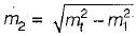
Now,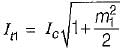
or,
After modulating with the second signal, we have
We know that, the overall modulation index is:
or,
Now,
or,
After modulating with the second signal, we have
An AM broadcast station is found to be transmitting modulating frequencies up to 5 kHz and the station is allowed to transmit on a frequency of 950 kHz, then what will be the bandwidth (in kHz) allotted to the station?- a)5
- b)10
- c)20
- d)25
Correct answer is option 'B'. Can you explain this answer?
An AM broadcast station is found to be transmitting modulating frequencies up to 5 kHz and the station is allowed to transmit on a frequency of 950 kHz, then what will be the bandwidth (in kHz) allotted to the station?
a)
5
b)
10
c)
20
d)
25

|
Cstoppers Instructors answered |
Concept:
Standard expression for AM expression for a message signal AmCosωmt is
S(t) = AC(1 + μCosωmt )cos ωct
Where;
ωm → Modulating frequency (rad/sec) = 2πfm
Bandwidth = 2fm
Calculation:
Given;
Modulating frequency (fm) = 5 KHz
Bandwidth = 2fm = (2 × 5) = 10 KHz
Which of the following is NOT one of the types of amplitude modulation?- a)Vestigial sideband
- b)Single-sideband with carrier
- c)Single-sideband suppressed carrier
- d)Double-sideband suppressed carrier
Correct answer is option 'B'. Can you explain this answer?
Which of the following is NOT one of the types of amplitude modulation?
a)
Vestigial sideband
b)
Single-sideband with carrier
c)
Single-sideband suppressed carrier
d)
Double-sideband suppressed carrier
|
|
Harshit Thakkar answered |
Single-sideband with carrier
Single-sideband with carrier modulation is NOT one of the types of amplitude modulation. This type of modulation involves the transmission of only one of the sidebands along with the carrier signal, resulting in a more efficient use of bandwidth compared to double-sideband modulation.
Types of Amplitude Modulation:
- Vestigial sideband: In vestigial sideband modulation, one sideband is partially suppressed to reduce bandwidth while still retaining the necessary information for demodulation.
- Single-sideband suppressed carrier: Single-sideband suppressed carrier modulation involves the transmission of only one sideband without the carrier signal, which helps in reducing bandwidth requirements.
- Double-sideband suppressed carrier: In double-sideband suppressed carrier modulation, both sidebands are transmitted without the carrier signal, resulting in efficient use of bandwidth.
Explanation:
Single-sideband with carrier modulation is not a commonly used modulation technique in practice. It is not as efficient in terms of bandwidth utilization compared to other types of amplitude modulation. Therefore, it is important to understand the different types of modulation techniques available in order to choose the most suitable one for a particular application.
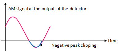
The types of distortions which can occur in the envelope detector output is/are
- a)only diagonal clipping.
- b)only negative peak clipping.
- c)both diagonal clipping and negative peak clipping.
- d)neither diagonal clipping nor negative peak clipping.
Correct answer is option 'C'. Can you explain this answer?
The types of distortions which can occur in the envelope detector output is/are
a)
only diagonal clipping.
b)
only negative peak clipping.
c)
both diagonal clipping and negative peak clipping.
d)
neither diagonal clipping nor negative peak clipping.
|
|
Yash Patel answered |
Diagonal Clipping
This type of distortion occurs when the RC time constant of the load circuit is too long. Due to this, the RC circuit cannot follow the fast changes in the modulating envelop.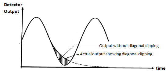
Negative Peak Clipping
This distortion occurs due to a fact that the modulation index on the output side of the detector is higher than that on its input side .
Hence, at higher depth of modulation of the transmitted signal, the overmodulation may takes place at the output of the detector .
The negative peak clipping will take place as a result of this overmodulation.
What is the percentage of power saved when an 80% modulated wave is transmitted over SSB-SC which was initially transmitted over AM?- a)0.8568
- b)0.8666
- c)0.8788
- d)0.8988
Correct answer is option 'C'. Can you explain this answer?
What is the percentage of power saved when an 80% modulated wave is transmitted over SSB-SC which was initially transmitted over AM?
a)
0.8568
b)
0.8666
c)
0.8788
d)
0.8988
|
|
Luminary Institute answered |
Concept:
Power of a transmitted AM wave is given as:
Power of a transmitted AM wave is given as:
Power in the carrier = Pc
Power in both the sidebands is given by:

Since the power is distributed equally to the left and to the right side of the sideband, the power in one of the sidebands is given by:

Analysis:
In SSB-SC, the carrier and one of the sidebands are suppressed, and when the carrier and 1 of the sideband are suppressed, the amount of power saving will be:
The percentage of power saved will be calculated as:
Given μ = 0.80, the amount of power saving will be
Power in both the sidebands is given by:
Since the power is distributed equally to the left and to the right side of the sideband, the power in one of the sidebands is given by:
Analysis:
In SSB-SC, the carrier and one of the sidebands are suppressed, and when the carrier and 1 of the sideband are suppressed, the amount of power saving will be:
The percentage of power saved will be calculated as:
Given μ = 0.80, the amount of power saving will be
The signal m(t) = cos(ωmt) is SSB (single side-band) modulated with a carrier cos(ωct) to get s(t). The signal obtained by passing s(t) through an ideal envelope detector is- a)cos(ωmt)
- b)sin(ωmt)
- c)cos(ωmt) + sin(ωmt)
- d)1
Correct answer is option 'D'. Can you explain this answer?
The signal m(t) = cos(ωmt) is SSB (single side-band) modulated with a carrier cos(ωct) to get s(t). The signal obtained by passing s(t) through an ideal envelope detector is
a)
cos(ωmt)
b)
sin(ωmt)
c)
cos(ωmt) + sin(ωmt)
d)
1
|
|
Sarita Yadav answered |
1) General equation of SSB modulated wave:
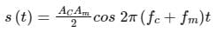
2) Output of envelope detector to signal
Acos ωct → A
Application:
Equation of SSB modulated signal
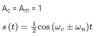
the output of envelope detector = ½
The output of the envelope detector is a constant voltage signal
Hence option (d) which represents a constant voltage is correct.
2) Output of envelope detector to signal
Acos ωct → A
Application:
Equation of SSB modulated signal
the output of envelope detector = ½
The output of the envelope detector is a constant voltage signal
Hence option (d) which represents a constant voltage is correct.
A carrier is simultaneously modulated by two sine waves with modulation indices of 0.4 and 0.3. The resultant modulation index will be- a)1.0
- b)0.7
- c)0.5
- d)0.35
Correct answer is 'C'. Can you explain this answer?
A carrier is simultaneously modulated by two sine waves with modulation indices of 0.4 and 0.3. The resultant modulation index will be
a)
1.0
b)
0.7
c)
0.5
d)
0.35
|
|
Avinash Mehta answered |
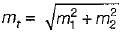
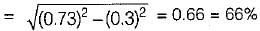
Given: m1 = 0.4, m2 = 0.3
Resultant modulation index = α^2 = 0.3^2 + 0.4^2 = 0.5^2 or
α = 0.5.
Consider the following statements:
1. The figure of merit of DSB-SC and SSB receivers with coherent detection is 1.
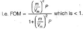
2. The figure of merit of an AM receiver with envelope detection is more than 1.
3. If the average modulated signal power and the average noise power in the message bandwidth is same as that of DSB-SCreceiver then the output SNR and figure of merit of SSB coherent receiver is same as that of the DSB SC receiver.
4. A square-law demodulator operates above threshold on a weaker signal than with an envelope demodulator.
Which of the above statements are correct?- a)1, 3 and 4
- b)2 and 4
- c)1, 2 and 4
- d)2 and 3
Correct answer is option 'A'. Can you explain this answer?
Consider the following statements:
1. The figure of merit of DSB-SC and SSB receivers with coherent detection is 1.
2. The figure of merit of an AM receiver with envelope detection is more than 1.
3. If the average modulated signal power and the average noise power in the message bandwidth is same as that of DSB-SCreceiver then the output SNR and figure of merit of SSB coherent receiver is same as that of the DSB SC receiver.
4. A square-law demodulator operates above threshold on a weaker signal than with an envelope demodulator.
Which of the above statements are correct?
a)
1, 3 and 4
b)
2 and 4
c)
1, 2 and 4
d)
2 and 3

|
Subhankar Malik answered |
- Statement-1 is correct.
- The figure of merit of an AM receiver with envelope detection is less than 1.
Hence, statement-2 is false. - Statement-3 and 4 are correct.
Which of the following modulation scheme is most bandwidth efficient?- a)AM
- b)FM
- c)PM
- d)SSB-SC
Correct answer is option 'D'. Can you explain this answer?
Which of the following modulation scheme is most bandwidth efficient?
a)
AM
b)
FM
c)
PM
d)
SSB-SC
|
|
Nakul Chauhan answered |
Bandwidth Efficiency of Modulation Schemes
The bandwidth efficiency of a modulation scheme refers to the amount of information that can be transmitted over a given bandwidth. In other words, it measures how efficiently the available bandwidth is utilized to transmit data. Among the given options (AM, FM, PM, SSB-SC), Single Sideband Suppressed Carrier (SSB-SC) modulation scheme is the most bandwidth efficient. Let's understand why.
1. AM (Amplitude Modulation)
- In AM, the amplitude of the carrier signal is varied in proportion to the message signal.
- The bandwidth required for AM is twice the frequency of the message signal.
- AM uses a lot of bandwidth to transmit the information and is not considered bandwidth efficient.
2. FM (Frequency Modulation)
- In FM, the frequency of the carrier signal is varied in proportion to the message signal.
- The bandwidth required for FM is determined by the maximum frequency deviation and the highest frequency component in the message signal.
- FM requires a wider bandwidth compared to AM, but it provides better noise immunity.
3. PM (Phase Modulation)
- In PM, the phase of the carrier signal is varied in proportion to the message signal.
- The bandwidth required for PM is also determined by the maximum frequency deviation and the highest frequency component in the message signal.
- PM requires a wider bandwidth compared to AM as well.
4. SSB-SC (Single Sideband Suppressed Carrier)
- SSB-SC is a modulation scheme that suppresses one of the sidebands and the carrier signal.
- By suppressing the carrier and one sideband, SSB-SC effectively reduces the required bandwidth.
- SSB-SC can achieve a bandwidth efficiency of 100%, meaning it utilizes the entire available bandwidth for transmission.
Conclusion
Among the given modulation schemes, Single Sideband Suppressed Carrier (SSB-SC) is the most bandwidth efficient. It achieves this by suppressing the carrier and one sideband, effectively utilizing the entire available bandwidth for transmission. In contrast, AM, FM, and PM require wider bandwidths, making them less efficient in terms of bandwidth utilization.
A DSB-SC signal is generated using the carrier signal cos (ωct + θ) and modulating signal m(t). What is the envelope detector output of this DSB-SC signal?- a)m(t) cos θ
- b)|m(t)|
- c)m(t) tan θ
- d)m(t) sin θ
Correct answer is option 'B'. Can you explain this answer?
A DSB-SC signal is generated using the carrier signal cos (ωct + θ) and modulating signal m(t). What is the envelope detector output of this DSB-SC signal?
a)
m(t) cos θ
b)
|m(t)|
c)
m(t) tan θ
d)
m(t) sin θ
|
|
Surya Iyer answered |
Ωc t) and the message signal m(t). The DSB-SC signal can be represented as:
s(t) = Ac * cos(ωc t) * m(t)
Where Ac is the amplitude of the carrier signal, ωc is the angular frequency of the carrier signal, and m(t) is the message signal.
This DSB-SC signal is generated by multiplying the carrier signal cos(ωc t) with the message signal m(t). The carrier signal provides the frequency and phase information, while the message signal carries the desired information to be transmitted.
The resulting DSB-SC signal contains two sidebands, one above and one below the carrier frequency. The carrier frequency itself is suppressed, hence the name Double Sideband Suppressed Carrier (DSB-SC). The sidebands carry the same information as the message signal, but shifted in frequency.
To demodulate the DSB-SC signal and recover the original message signal, a coherent demodulator is used. This involves multiplying the DSB-SC signal with a local oscillator signal that has the same frequency and phase as the carrier signal used in the modulation process. The resulting product is then passed through a low-pass filter to remove the high-frequency components and extract the original message signal.
DSB-SC modulation is commonly used in applications such as AM radio broadcasting, where the message signal is an audio signal and the carrier signal is a high-frequency radio wave. By using DSB-SC modulation, the audio signal can be transmitted efficiently over long distances.
Which of the following circuits could NOT be used as demodulator of SSB?- a)Weaver Demodulator
- b)Phase Shift Method
- c)Phase discriminator
- d)Filter Method
Correct answer is option 'C'. Can you explain this answer?
Which of the following circuits could NOT be used as demodulator of SSB?
a)
Weaver Demodulator
b)
Phase Shift Method
c)
Phase discriminator
d)
Filter Method
|
|
Luminary Institute answered |
Phase Discrimination is used for the demodulation of Frequency Modulate signals.
Direction: Two statements are given. Based on the given information, choose the correct answer.Statement-I: For the same message signal, the pre-detection SNR is double in the case of conventional practical AM modulation, than that in the case of SSB.
Statement-II: The AM signal bandwidth is double as compared to SSB signal bandwidth.- a)Statement I and Statement II are correct and Statement II is the correct explanation of Statement I.
- b)Statement I and Statement II are correct but Statement II is not the correct explanation of Statement I
- c)Statement I is correct, Statement II is false
- d)Statement I is false, Statement II is correct
Correct answer is option 'D'. Can you explain this answer?
Direction: Two statements are given. Based on the given information, choose the correct answer.
Statement-I: For the same message signal, the pre-detection SNR is double in the case of conventional practical AM modulation, than that in the case of SSB.
Statement-II: The AM signal bandwidth is double as compared to SSB signal bandwidth.
Statement-II: The AM signal bandwidth is double as compared to SSB signal bandwidth.
a)
Statement I and Statement II are correct and Statement II is the correct explanation of Statement I.
b)
Statement I and Statement II are correct but Statement II is not the correct explanation of Statement I
c)
Statement I is correct, Statement II is false
d)
Statement I is false, Statement II is correct
|
|
Sarita Yadav answered |
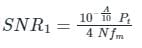
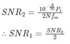
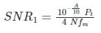
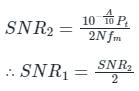
Let, the channel is practical having finite attenuation of 'A' dB, and the single-sided noise power spectral density is given as 'N' W/Hz
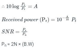
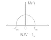
Let the message signal spectrum is given as:
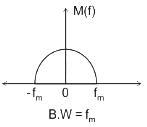
In the case of AM:-
B.W = 2fm kHz (twice of message signal bandwidth)
In the case of SSB:-
B.W = fm kHz (same as message signal bandwidth)
In the case of SSB:-
B.W = fm kHz (same as message signal bandwidth)
∴ SNR in the case of S.S.B is double that in the case of AM.
Statement-I is incorrect and Statement-II is correct.
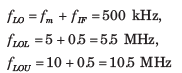
A super heterodyne receiver is designed to receive transmitted signals between 5 and 10 MHz. High-side tuning is to be used. The tuning range of the local oscillator for IF frequency 500 kHz would be- a)4.5 MHz - 9.5 MHz
- b)5.5 MHz - 10.5 MHz
- c)4.5 MHz - 10.5 MHz
- d)None of the above
Correct answer is option 'B'. Can you explain this answer?
A super heterodyne receiver is designed to receive transmitted signals between 5 and 10 MHz. High-side tuning is to be used. The tuning range of the local oscillator for IF frequency 500 kHz would be
a)
4.5 MHz - 9.5 MHz
b)
5.5 MHz - 10.5 MHz
c)
4.5 MHz - 10.5 MHz
d)
None of the above

|
Varun Banerjee answered |
Since High-side tuning is used
Which of the following requires the least bandwidth?- a)DSB SC
- b)DSB
- c)VSB
- d)SSB
Correct answer is option 'D'. Can you explain this answer?
Which of the following requires the least bandwidth?
a)
DSB SC
b)
DSB
c)
VSB
d)
SSB
|
|
Sakshi Chauhan answered |
Bandwidth Requirement for Different Modulation Techniques:
DSB SC (Double Sideband Suppressed Carrier):
- DSB SC modulation requires more bandwidth compared to other modulation techniques because it transmits both sidebands along with the carrier signal.
- It utilizes the full bandwidth available for transmission.
DSB (Double Sideband):
- DSB modulation also transmits both sidebands without the carrier signal.
- It requires more bandwidth than SSB but less than DSB SC.
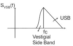
VSB (Vestigial Sideband):
- VSB modulation transmits one complete sideband and a portion of the other sideband.
- It requires more bandwidth than SSB but less than DSB and DSB SC.
SSB (Single Sideband):
- SSB modulation transmits only one sideband while suppressing the other sideband and the carrier signal.
- It requires the least bandwidth among the listed modulation techniques.
- By eliminating redundant information, SSB modulation efficiently uses the available bandwidth.
In conclusion, SSB modulation requires the least bandwidth among DSB SC, DSB, VSB, and SSB modulation techniques. Its efficiency in utilizing bandwidth makes it a suitable choice for applications where bandwidth conservation is essential.
DSB SC (Double Sideband Suppressed Carrier):
- DSB SC modulation requires more bandwidth compared to other modulation techniques because it transmits both sidebands along with the carrier signal.
- It utilizes the full bandwidth available for transmission.
DSB (Double Sideband):
- DSB modulation also transmits both sidebands without the carrier signal.
- It requires more bandwidth than SSB but less than DSB SC.
VSB (Vestigial Sideband):
- VSB modulation transmits one complete sideband and a portion of the other sideband.
- It requires more bandwidth than SSB but less than DSB and DSB SC.
SSB (Single Sideband):
- SSB modulation transmits only one sideband while suppressing the other sideband and the carrier signal.
- It requires the least bandwidth among the listed modulation techniques.
- By eliminating redundant information, SSB modulation efficiently uses the available bandwidth.
In conclusion, SSB modulation requires the least bandwidth among DSB SC, DSB, VSB, and SSB modulation techniques. Its efficiency in utilizing bandwidth makes it a suitable choice for applications where bandwidth conservation is essential.
The process of recovering information signal from received carrier is known as ______.- a)modulation
- b)encoding
- c)demodulator
- d)sampling
Correct answer is option 'C'. Can you explain this answer?
The process of recovering information signal from received carrier is known as ______.
a)
modulation
b)
encoding
c)
demodulator
d)
sampling

|
Starcoders answered |
Modulation:
The process in which the characteristics of carrier signal is varied in accordance with baseband message signal to make bandpass signal.
Sampling :
The process of conversion of continuous time signals into discrete time signal.
Encoding :
The process of putting the message in the form in which it is to be communicated.
ex: Analog signal into digital form.
Demodulation :
The process of recovery of message signal from modulated signal.
Hence correct option is "3".
Modulation system used for video modulation in TV transmission is- a)DSB
- b)VSB
- c)SSB
- d)SSBBC
Correct answer is option 'B'. Can you explain this answer?
Modulation system used for video modulation in TV transmission is
a)
DSB
b)
VSB
c)
SSB
d)
SSBBC
|
|
Cstoppers Instructors answered |
In TV Transmission the use of FM is made for Audio transmission and AM for Video transmission.
Vestigial Sideband modulation (VSB) is used for video modulation in TV transmission due to the following reasons :
Vestigial Sideband modulation (VSB) is used for video modulation in TV transmission due to the following reasons :
- Video signal exhibits a large bandwidth and significant low-frequency content which suggests the use of VSB.
- VSB (vestigial side band) transmission transmits one side band fully and the other side band partially thus, reducing the bandwidth requirement.
- The circuitry for demodulation in the receiver should be simple and therefore cheap. VSB demodulation uses a simple envelope detection.
In amplitude modulation, the modulation envelope has a peak value which is double the unmodulated carrier value. What is the value of the modulation index ?- a)25%
- b)50%
- c)75%
- d)100%
Correct answer is option 'D'. Can you explain this answer?
In amplitude modulation, the modulation envelope has a peak value which is double the unmodulated carrier value. What is the value of the modulation index ?
a)
25%
b)
50%
c)
75%
d)
100%

|
Pranavi Gupta answered |
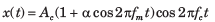
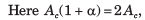 Thus α = 1, therefor modulation index is 1 or 100% modulation.
How much percentage power will be saved when the carrier and one of the sidebands are suppressed in an AM wave modulated to a depth of 50%?- a)83.3%
- b)94.4%
- c)47.2%
- d)None of the above
Correct answer is option 'B'. Can you explain this answer?
How much percentage power will be saved when the carrier and one of the sidebands are suppressed in an AM wave modulated to a depth of 50%?
a)
83.3%
b)
94.4%
c)
47.2%
d)
None of the above
|
|
Cstoppers Instructors answered |
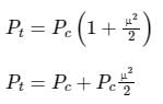
Concept:
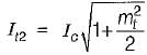
Total power in AM (PT)= PC ( 1 + μ2/2 ) = PC + PCμ2/2
where;
PC → Carrier power
μ → modulation index
Power of single sideband = ( PCμ2/2)/2 = PCμ2/4
Calculation:
Given
μ = 50% = 0.5
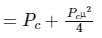
After suppressing carrier and a single sideband :
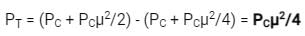
PT = (PC + PCμ2/2) - (PC + PCμ2/4) = PCμ2/4
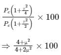
Percentage of power will be saved :
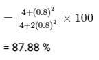
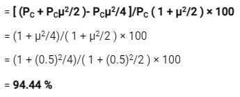
= [(PC + PCμ2/2 )- PCμ2/4 ]/PC ( 1 + μ2/2 ) × 100
= (1 + μ2/4)/( 1 + μ2/2 ) × 100
= (1 + (0.5)2/4)/( 1 + (0.5)2/2 ) × 100
= 94.44 %
Which of the following circuits could NOT be used as demodulator of SSB?- a)Weaver Demodulator
- b)Phase Shift Method
- c)Phase discriminator
- d)Filter Method
Correct answer is option 'C'. Can you explain this answer?
Which of the following circuits could NOT be used as demodulator of SSB?
a)
Weaver Demodulator
b)
Phase Shift Method
c)
Phase discriminator
d)
Filter Method
|
|
Tanya Chauhan answered |
Phase Discriminator
Phase discriminators are not suitable for demodulating SSB signals because they rely on detecting phase differences between the input signal and a reference signal. SSB signals have suppressed carrier and contain both upper and lower sidebands, making it challenging for a phase discriminator to accurately demodulate the signal.
Weaver Demodulator
A Weaver demodulator is a popular choice for demodulating SSB signals. It works by mixing the SSB signal with a local oscillator signal to generate both upper and lower sidebands. The unwanted sideband is then suppressed using a filter, resulting in the demodulated signal.
Phase Shift Method
The phase shift method is another common technique for demodulating SSB signals. It involves shifting the phase of the input signal by 90 degrees and then combining it with the original signal. The resulting signal is then low-pass filtered to extract the baseband signal.
Filter Method
The filter method is also used for demodulating SSB signals. It involves passing the SSB signal through a bandpass filter to select either the upper or lower sideband. The selected sideband is then further processed to obtain the demodulated signal.
In conclusion, while phase discriminators are not suitable for demodulating SSB signals, the Weaver demodulator, phase shift method, and filter method are all viable options for this purpose.


Which of the following modulation scheme is most bandwidth efficient?- a)AM
- b)FM
- c)PM
- d)SSB-SC
Correct answer is option 'D'. Can you explain this answer?
Which of the following modulation scheme is most bandwidth efficient?
a)
AM
b)
FM
c)
PM
d)
SSB-SC
|
|
Luminary Institute answered |
The bandwidth of different modulation schemes are as shown:
AM → 2fm
SSB-SC → fm
For angle modulated schemes (FM and PM)
= 2(β + 1) fm
fm = message signal bandwidth
So, for SSB-SC, the bandwidth requirement is minimal.
In the phase shift SSB method to get upper side band- a)make two LSBs 180° out of phase
- b)make two LSBs in phase
- c)reduce the effect of noise pulses
- d)limit the noise bandwidth
Correct answer is option 'A'. Can you explain this answer?
In the phase shift SSB method to get upper side band
a)
make two LSBs 180° out of phase
b)
make two LSBs in phase
c)
reduce the effect of noise pulses
d)
limit the noise bandwidth
|
|
Luminary Institute answered |
Concept:
SSB (Single Side Band) modulation is a technique that allows only one sideband to pass saving bandwidth and power both. Practically it is very difficult to pass only a single sideband.
Analysis:
Ex: If we consider a single-tone modulating signal as x(t) = cos ωmt, the SSB modulated wave with only the upper sideband will be represented as:
cos ((ωc + ωm)t) = cos ωc.cos ωmt – sin ωc.sin ωmt
and with lower sideband only will be represented as:
cos (ωc - ωm)t = cos ωct .cos ωmt + sin ωct. sin ωmt
where sin ωmt is the Hilbert transform of the original message signal x(t) = cos ωmt
Conclusion:
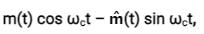
Generalizing this for any signal m(t), we can say that the SSB modulated signal with only upper sideband will be:
m(t) cos ωct – m̂(t) sin ωct,
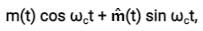
Similarly, we can say that the SSB modulated signal with only lower sideband will be:
m(t) cos ωct + m̂(t) sin ωct,
where m̂(t) is the Hilbert transform of m(t).
SSB/SC is generated using a balanced modulator circuit as shown:
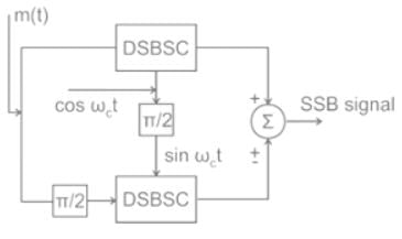
Where π/2 phase shifter gives the Hilbert transform of the incoming signal.
Where π/2 phase shifter gives the Hilbert transform of the incoming signal.
Consider the following statements associated with the synchronous detection method for detection/demodulation of AM signals:
1. The circuit complexity is very less.
2. It introduces frequency and phase errors only.
3. it does not require any locally generated synchronous carrier.
4. It can be used for DSB-SC, SSB and VSB but not for DSB-FC.
Which of the statements given above is/are correct?- a)1, 3 and 4
- b)2 and 4 only
- c)1, 2 and 3
- d)3 and 4 only
Correct answer is option 'B'. Can you explain this answer?
Consider the following statements associated with the synchronous detection method for detection/demodulation of AM signals:
1. The circuit complexity is very less.
2. It introduces frequency and phase errors only.
3. it does not require any locally generated synchronous carrier.
4. It can be used for DSB-SC, SSB and VSB but not for DSB-FC.
Which of the statements given above is/are correct?
1. The circuit complexity is very less.
2. It introduces frequency and phase errors only.
3. it does not require any locally generated synchronous carrier.
4. It can be used for DSB-SC, SSB and VSB but not for DSB-FC.
Which of the statements given above is/are correct?
a)
1, 3 and 4
b)
2 and 4 only
c)
1, 2 and 3
d)
3 and 4 only
|
|
Saikat Gupta answered |
• The circuit complexity of synchronous detection is very high. Hence, statement-1 is not correct.
• Statement-2 is correct.
• Synchronous detection require a locally generated synchronous carrier. Hence, statement-3 is not correct.
• Statement-4 is correct because synchronous detection is used for DSB-SC, SSB and VSB while envelope detection is used for DSB-FC only.
• Statement-2 is correct.
• Synchronous detection require a locally generated synchronous carrier. Hence, statement-3 is not correct.
• Statement-4 is correct because synchronous detection is used for DSB-SC, SSB and VSB while envelope detection is used for DSB-FC only.
How much percentage power will be saved when the carrier and one of the sidebands are suppressed in an AM wave modulated to a depth of 50% ?- a)83.3%
- b)94.4%
- c)47.2%
- d)None of the above
Correct answer is option 'B'. Can you explain this answer?
How much percentage power will be saved when the carrier and one of the sidebands are suppressed in an AM wave modulated to a depth of 50% ?
a)
83.3%
b)
94.4%
c)
47.2%
d)
None of the above
|
|
Sarita Yadav answered |
Concept:
Total power in AM (PT)= PC( 1 + μ2/2 ) = PC + PCμ2/2
where;
PC → Carrier power
μ → modulation index
Power of single sideband = ( PCμ2/2)/2 = PCμ2/4
Total power in AM (PT)= PC( 1 + μ2/2 ) = PC + PCμ2/2
where;
PC → Carrier power
μ → modulation index
Power of single sideband = ( PCμ2/2)/2 = PCμ2/4
Calculation:
Given
μ = 50% = 0.5
After suppressing carrier and a single sideband :
Percentage of power will be saved :
Given
μ = 50% = 0.5
After suppressing carrier and a single sideband :
Percentage of power will be saved :
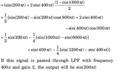
Suppose we wish to transmit the signal x(t) = sin 200πt + 2 sin 400πt using a modulation that create the signal g(t) = x(t) sin 400πt. If the product g(t) sin 400πt is passed through an ideal LPF with cutoff frequency 400π and pass band gain of 2, the signal obtained at the output of the LPF is- a)sin200πt
- b)1/2 sin200πt
- c)2sin 200πt
- d)0
Correct answer is option 'A'. Can you explain this answer?
Suppose we wish to transmit the signal x(t) = sin 200πt + 2 sin 400πt using a modulation that create the signal g(t) = x(t) sin 400πt. If the product g(t) sin 400πt is passed through an ideal LPF with cutoff frequency 400π and pass band gain of 2, the signal obtained at the output of the LPF is
a)
sin200πt
b)
1/2 sin200πt
c)
2sin 200πt
d)
0

|
Manisha Chavan answered |

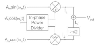
In this circuit, Vout is:- a)Upper Sideband (ωL + ωm)
- b)Lower Sideband (ωL - ωm)
- c)Both Upper and Lower Sideband (ωL ± ωm)
- d)None of above
Correct answer is option 'A'. Can you explain this answer?
In this circuit, Vout is:
a)
Upper Sideband (ωL + ωm)
b)
Lower Sideband (ωL - ωm)
c)
Both Upper and Lower Sideband (ωL ± ωm)
d)
None of above
|
|
Luminary Institute answered |
Concept:
A single sideband (SSB) AM Signal is represented as

m̂(t) → represent Hilbert transform of message signal
(-) → sign represent USB
(+) → sign represent LSB
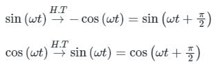
Hilbert transform:
It is a specific Linear operator that takes a function u(t) of a real variable and produces another function of real variable H(u)(t)
→ It imparts a phase shift of ± 90° (π/2 radians) to every frequency component of a function.
Explanation:
From the given Block diagram.
I1 = (Am sin ωmt)(Ac cos ωct)
I2 = (Am cos ωmt)(Ac cos ωct)
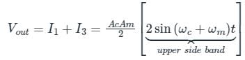
Vout = I1 + I3
From I1
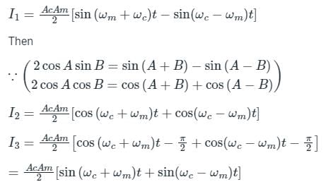
Option (A) correct choice.
Short trick:
Observe the Vout in block diagram i.e. Vout = I1 + I3
But in I3 there is –π/2 phase change so the SSB becomes in the Form of
S(t) = m(t) cos ωct – m̂(t) sin ωct
And (-) sign represent USB only.
So the student can tick the correct answer.
In a DSB-SC system with 100% modulation, the power saving is- a)50%
- b)66%
- c)75%
- d)100%
Correct answer is option 'B'. Can you explain this answer?
In a DSB-SC system with 100% modulation, the power saving is
a)
50%
b)
66%
c)
75%
d)
100%

|
Shivam Sharma answered |
This is so because the power is suppressed by two thirds of the total. hence the power saving is 66%.
The carrier amplitude after AM varies between 4 volts and 1 volt. The depth of modulation is- a)72%
- b)55%
- c)60%
- d)80%
Correct answer is option 'C'. Can you explain this answer?
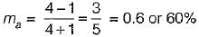
The carrier amplitude after AM varies between 4 volts and 1 volt. The depth of modulation is
a)
72%
b)
55%
c)
60%
d)
80%

|
Ishani Chauhan answered |
We know that,
Modulation index;
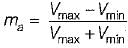
Given, Vmax = 4 volt and Vmin = 1 volt
∴
Modulation index;
Given, Vmax = 4 volt and Vmin = 1 volt
∴
A diode detector has a load of 1 kΩ shunted by a 10000 pF capacitor. The diode has a forward resistance of 1 Ω. The maximum permissible depth of modulation,so as to avoid diagonal clipping, with modulating signal frequency fo 10 kHz will be- a)0.847
- b)0.628
- c)0.734
- d)None of the above
Correct answer is option 'A'. Can you explain this answer?
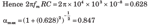
A diode detector has a load of 1 kΩ shunted by a 10000 pF capacitor. The diode has a forward resistance of 1 Ω. The maximum permissible depth of modulation,so as to avoid diagonal clipping, with modulating signal frequency fo 10 kHz will be
a)
0.847
b)
0.628
c)
0.734
d)
None of the above

|
Diya Dasgupta answered |

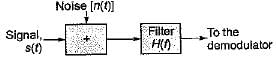
In order to minimize the noise power a filter is introduced- a)before modulator
- b)after demodulator
- c)before demodulator
- d)after modulator
Correct answer is option 'C'. Can you explain this answer?
In order to minimize the noise power a filter is introduced
a)
before modulator
b)
after demodulator
c)
before demodulator
d)
after modulator

|
Neha Basak answered |
In order to minimize the noise power that is presented to the demodulator of a receiver, a filter is introduced before the demodulator as shown below.
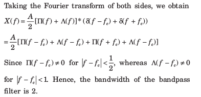
The frequency response H(ω) of a VSB filter is shown below.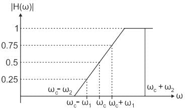 Find the VSB signal XVSB(t) when m(t) = a1 cos ω1t + a2 cos ω2t
- a)(a1/8) cos (ωc - ω1)t + (2a1/8) cos (ωc + ω1)t + a2 cos (ωc + ω2)t
- b)(a1/8) cos (ωc - ω1)t + (3a1/8) cos (ωc + ω1)t + (a2/2) cos (ωc + ω2)t
- c)(a1/8) cos (ωc - ω2)t + (3a1/8) cos (ωc - ω1)t
- d)(a1/4) cos (ωc - ω2t) + (2a1/8) cos (ωc + ω1t + (a2/4) cos (ωc + ω2)t
Correct answer is option 'B'. Can you explain this answer?
The frequency response H(ω) of a VSB filter is shown below.
Find the VSB signal XVSB(t) when m(t) = a1 cos ω1t + a2 cos ω2t
a)
(a1/8) cos (ωc - ω1)t + (2a1/8) cos (ωc + ω1)t + a2 cos (ωc + ω2)t
b)
(a1/8) cos (ωc - ω1)t + (3a1/8) cos (ωc + ω1)t + (a2/2) cos (ωc + ω2)t
c)
(a1/8) cos (ωc - ω2)t + (3a1/8) cos (ωc - ω1)t
d)
(a1/4) cos (ωc - ω2t) + (2a1/8) cos (ωc + ω1t + (a2/4) cos (ωc + ω2)t
|
|
Sarita Yadav answered |
Concept:
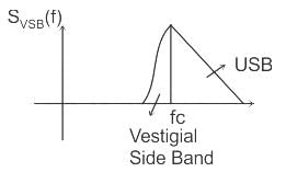
VSB (vestigial sideband) transmission transmits one sideband fully and the other sideband partially thus, reducing the bandwidth requirement.
The spectrum of a vestigial sideband is as shown:
VSB (vestigial sideband) transmission transmits one sideband fully and the other sideband partially thus, reducing the bandwidth requirement.
The spectrum of a vestigial sideband is as shown:
Analysis:
xDSB(t) = m(t) cos ωct
= [a1 cos ω1t + a2 cos ω2t] cos ωct
= a1 cos ω1t cos ωct + a2 cos ω2t cos ωct
= a1/2 [cos (ωc - ω1)t + cos (ωc + ω1)t] + a2/2 [cos (ωc - ω2)t + cos (ωc - ω2)t
so, these are the sinusoids that passes through H(ω) and are having gains
0.25, 0.75, 0, 1
∴ xDSB(t) = (a1/8) cos(ωc - ω1)t + (3a1/8) cos(ωc + ω1)t + 0 + (a2/2) cos(ωc + ω2)t
VSB modulation is termed as ___________.- a)Vestigial sideband
- b)Vertical sideband
- c)Single side-band
- d)Variable sideband
Correct answer is option 'A'. Can you explain this answer?
VSB modulation is termed as ___________.
a)
Vestigial sideband
b)
Vertical sideband
c)
Single side-band
d)
Variable sideband

|
Uday Kumar answered |
VSB Modulation
VSB modulation stands for Vestigial Sideband Modulation. It is a modulation technique that is widely used in communication systems for transmitting TV signals.
Explanation
VSB modulation is a type of amplitude modulation technique that transmits a signal by suppressing one of the sidebands and partially suppressing the other. In this technique, the carrier signal is modulated by the baseband signal, and then the modulated signal is filtered using a bandpass filter.
The bandpass filter in VSB modulation allows the frequency band to pass which is required to transmit the video signal. The lower sideband is completely suppressed, and the upper sideband is partially suppressed. This partial suppression of the upper sideband is called the vestigial sideband.
Advantages
Some of the advantages of VSB modulation are:
1. VSB modulation is bandwidth-efficient.
2. It requires less transmission power compared to other modulation techniques.
3. It provides good signal-to-noise ratio.
4. It provides high-quality video transmission.
Applications
Some of the applications of VSB modulation are:
1. TV broadcasting
2. Cable TV transmission
3. Satellite TV transmission
4. Video conferencing
Conclusion
In conclusion, VSB modulation is a widely used modulation technique in communication systems for transmitting TV signals. It is bandwidth-efficient, requires less transmission power, and provides high-quality video transmission.
The output signal to noise ratio depends upon .- a)the type of modulation used at the transmitter only.
- b)the type of demodulation used at the receiver only.
- c)the type of modulation used at the transmitter and the type of demodulation used at the receiver.
- d)none of the above
Correct answer is option 'C'. Can you explain this answer?
The output signal to noise ratio depends upon .
a)
the type of modulation used at the transmitter only.
b)
the type of demodulation used at the receiver only.
c)
the type of modulation used at the transmitter and the type of demodulation used at the receiver.
d)
none of the above
|
|
Bhumi Patel answered |
Understanding Signal to Noise Ratio (SNR)
The Signal to Noise Ratio (SNR) is a crucial measurement in communication systems, indicating the quality of the signal relative to the noise present. Various factors influence SNR, particularly the modulation at the transmitter and the demodulation at the receiver.
Factors Influencing SNR
- Type of Modulation:
Different modulation techniques (like AM, FM, QAM) have varying resilience to noise. For example, frequency modulation (FM) can offer better noise immunity compared to amplitude modulation (AM). This means that the choice of modulation can significantly affect the SNR at the receiver end.
- Type of Demodulation:
The receiver's ability to accurately demodulate the signal also plays a vital role. Advanced demodulation techniques can recover the signal effectively, even in the presence of noise, thereby enhancing the overall SNR. For instance, coherent demodulation techniques can outperform non-coherent methods in terms of SNR.
Combined Effect of Modulation and Demodulation
- Interdependence:
The SNR is not solely dependent on either the modulation or demodulation but rather a combination of both. A robust modulation scheme paired with an efficient demodulation method can lead to a significantly higher SNR.
- System Performance:
The overall system performance is optimized when both aspects are considered. Poor modulation can lead to low-quality signals, which may not improve even with a sophisticated demodulator. Conversely, a good modulator can only perform optimally when the receiver is equipped with an appropriate demodulator.
In conclusion, the correct answer is option 'C' because the output SNR is influenced by both the modulation technique used at the transmitter and the demodulation technique employed at the receiver.
Vestigial sideband is most commonly used in-- a)microwave transmission
- b)Television transmission
- c)Radio transmission
- d)Telephony
- e)All of the options
Correct answer is option 'B'. Can you explain this answer?
Vestigial sideband is most commonly used in-
a)
microwave transmission
b)
Television transmission
c)
Radio transmission
d)
Telephony
e)
All of the options
|
|
Nishant Sethi answered |
Introduction:
Vestigial sideband (VSB) modulation is a technique used in communication systems to transmit information. It is commonly used in television transmission due to its ability to efficiently utilize the available bandwidth.
Explanation:
Television transmission requires the transmission of both audio and video signals. These signals contain a large amount of information that needs to be transmitted simultaneously. Vestigial sideband modulation provides an effective way to transmit this information without wasting bandwidth.
What is Vestigial Sideband (VSB) Modulation?
Vestigial sideband modulation is a type of amplitude modulation (AM) technique. In VSB modulation, the upper and lower sidebands of the modulated signal are partially suppressed, leaving only a small portion of one sideband. This allows for efficient utilization of the available bandwidth.
Advantages of Vestigial Sideband (VSB) Modulation:
- Bandwidth Efficiency: VSB modulation allows for the transmission of a large amount of information within a limited bandwidth. By suppressing the unnecessary sidebands, more channels can be accommodated within the given frequency spectrum.
- Compatibility: VSB modulation is compatible with existing AM receivers. This allows for backward compatibility, as older receivers can still receive VSB-modulated signals.
- Reduced Interference: The suppression of sidebands in VSB modulation reduces the interference caused by adjacent channels. This leads to improved signal quality and reduced cross-talk between channels.
Application in Television Transmission:
Television signals contain both audio and video components. These components require a large bandwidth for transmission. VSB modulation is well-suited for television transmission due to its bandwidth efficiency and compatibility with existing receivers.
- Video Signal: The video signal in television transmission contains a wide range of frequencies. VSB modulation efficiently transmits this video signal by suppressing unnecessary sidebands, allowing for the transmission of high-quality video within a limited bandwidth.
- Audio Signal: The audio signal in television transmission is typically in the lower frequency range. VSB modulation allows for the transmission of the audio signal by suppressing the upper sideband and transmitting the vestigial sideband, which contains the necessary audio information.
Conclusion:
Vestigial sideband (VSB) modulation is commonly used in television transmission due to its bandwidth efficiency and compatibility with existing receivers. By suppressing unnecessary sidebands, VSB modulation allows for the efficient transmission of both audio and video signals within a limited bandwidth.
Direction: Two statements are given. Based on the given information, choose the correct answer.Statement-I: For the same message signal, the pre-detection SNR is double in the case of conventional practical AM modulation, than that in the case of SSB.Statement-II: The AM signal bandwidth is double as compared to SSB signal bandwidth.- a)Statement I and Statement II are correct and Statement II is the correct explanation of Statement I.
- b)Statement I and Statement II are correct but Statement II is not the correct explanation of Statement I
- c)Statement I is correct, Statement II is false
- d)Statement I is false, Statement II is correct
Correct answer is option 'D'. Can you explain this answer?
Direction: Two statements are given. Based on the given information, choose the correct answer.
Statement-I: For the same message signal, the pre-detection SNR is double in the case of conventional practical AM modulation, than that in the case of SSB.
Statement-II: The AM signal bandwidth is double as compared to SSB signal bandwidth.
a)
Statement I and Statement II are correct and Statement II is the correct explanation of Statement I.
b)
Statement I and Statement II are correct but Statement II is not the correct explanation of Statement I
c)
Statement I is correct, Statement II is false
d)
Statement I is false, Statement II is correct
|
|
Luminary Institute answered |
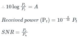
Let, the channel is practical having finite attenuation of 'A' dB, and the single-sided noise power spectral density is given as 'N' W/Hz
Let the message signal spectrum is given as:
Let the message signal spectrum is given as:
In the case of AM:-
B.W = 2fm kHz (twice of message signal bandwidth)
In the case of SSB:-
B.W = fm kHz (same as message signal bandwidth)
∴ SNR in the case of S.S.B is double that in the case of AM.
Statement-I is incorrect and Statement-II is correct.
The modulation technique that takes the lowest bandwidth among the given- a)AM
- b)FM
- c)DSB-SC
- d)SSB-SC
Correct answer is option 'D'. Can you explain this answer?
The modulation technique that takes the lowest bandwidth among the given
a)
AM
b)
FM
c)
DSB-SC
d)
SSB-SC
|
|
Sarita Yadav answered |
The modulation technique that takes the lowest bandwidth is SSB-SC
Single Side Band (SSB SC):
- SSB SC is a form of amplitude modulation where only a single sideband is transmitted and 1 sideband and carrier are suppressed.
- The advantage of SSB is bandwidth and power-saving over both conventional AM and DSB SC, i.e. DSB SC has a more power consumption than SSB SC.
- The Bandwidth requirement is only fm, ∴ It needs half the bandwidth than the DSB-SC transmission.
Comparison:
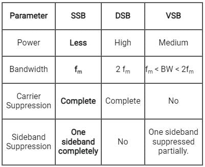
A VSB transmitter that transmits 25% of the other sideband along with the wanted sideband radiates 0.625 kW when the modulation percentage is 60%. If we want to transmit the same message by an AM transmitter then the carrier power (in kW) required is - a)6.56 kW
- b)5.56 kW
- c)4.56 kW
- d)7.56 kW
Correct answer is option 'B'. Can you explain this answer?
A VSB transmitter that transmits 25% of the other sideband along with the wanted sideband radiates 0.625 kW when the modulation percentage is 60%. If we want to transmit the same message by an AM transmitter then the carrier power (in kW) required is
a)
6.56 kW
b)
5.56 kW
c)
4.56 kW
d)
7.56 kW
|
|
Chhavi Gupta answered |
To understand why the correct answer is option B, let's break down the given information and analyze the concepts involved.
Given Information:
- VSB transmitter transmits 25% of the other sideband along with the wanted sideband.
- The radiated power is 0.625 kW when the modulation percentage is 60%.
Understanding VSB Transmitter:
VSB stands for Vestigial Sideband modulation, which is a type of amplitude modulation (AM) that transmits both sidebands but partially suppresses one of them. In this case, the VSB transmitter transmits 25% of the other sideband along with the desired sideband.
We know that the total power of an AM signal is given by the equation:
PAM = (1 + m^2/2) x Pc
Where PAM is the total power of the AM signal, m is the modulation index, and Pc is the carrier power.
Calculating the Carrier Power for VSB Transmitter:
Given that the radiated power is 0.625 kW when the modulation percentage is 60%, we can calculate the modulation index (m) using the equation:
m = (modulation percentage) / 100
m = 60 / 100
m = 0.6
Since the VSB transmitter transmits 25% of the other sideband, the modulation index for the VSB transmitter will be:
m_VSB = m x (1 - 0.25)
m_VSB = 0.6 x 0.75
m_VSB = 0.45
Now, we can use the total power equation to find the carrier power (Pc) for the VSB transmitter:
0.625 = (1 + 0.45^2/2) x Pc
Simplifying the equation:
0.625 = (1 + 0.10125) x Pc
0.625 = 1.10125 x Pc
Pc = 0.625 / 1.10125
Pc = 0.5665 kW
Transmitting the Same Message with an AM Transmitter:
To transmit the same message using an AM transmitter, we need to find the carrier power required. Since the VSB transmitter and AM transmitter both transmit the same message, the modulation index (m) will remain the same, which is 0.6.
Using the total power equation for AM:
PAM = (1 + m^2/2) x Pc_AM
We know that PAM for the VSB transmitter is 0.625 kW. Substituting the values into the equation:
0.625 = (1 + 0.6^2/2) x Pc_AM
Simplifying the equation:
0.625 = (1 + 0.18) x Pc_AM
0.625 = 1.18 x Pc_AM
Pc_AM = 0.625 / 1.18
Pc_AM = 0.5288 kW
Therefore, the carrier power required for the AM transmitter to transmit the same message is approximately 0.5288 kW, which is closest to option B (5.56 kW).
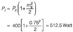
A 400 Watts carrier is modulated to a depth of 75 percent. Assuming the modulating signal to a sinusoidal one, the total power in the amplitude-modulated wave is- a)625 Watt
- b)426.8 Watt
- c)634.3 Watt
- d)512.5 Watt
Correct answer is option 'D'. Can you explain this answer?
A 400 Watts carrier is modulated to a depth of 75 percent. Assuming the modulating signal to a sinusoidal one, the total power in the amplitude-modulated wave is
a)
625 Watt
b)
426.8 Watt
c)
634.3 Watt
d)
512.5 Watt

|
Nabanita Saha answered |
Given,
Pc = 400 Watt, ma = 0.75
The total power in the amplitude modulated wave is:
Pc = 400 Watt, ma = 0.75
The total power in the amplitude modulated wave is:
The antenna current of an AM transmitter is 8 A if only the carrier is sent, but it increases to 8.93 A if the carrier is modulated by a single sinusoidal wave. What is the antenna current when the percent of modulation is 80%?
- a)9.2 A
- b)8.6 A
- c)6.6 A
- d)7.0 A
Correct answer is option 'A'. Can you explain this answer?
The antenna current of an AM transmitter is 8 A if only the carrier is sent, but it increases to 8.93 A if the carrier is modulated by a single sinusoidal wave. What is the antenna current when the percent of modulation is 80%?
a)
9.2 A
b)
8.6 A
c)
6.6 A
d)
7.0 A

|
Anmol Nair answered |
Given, Ic = 8 a, ma = 0.8
We know that, antenna current is
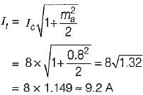
We know that, antenna current is

Which of the following statements are correct w.r.t. the vestigial sideband modulation?
(i) As compared to SSB-SC, the bandwidth of the vestigial sideband becomes larger.
(ii) The filter required needs to have a sharp cut-off.
(iii) The transmitted vestige of the undesired sideband compensates for the loss of the wanted sideband.
(iv) Vestigial sideband is used in TV for transmission of the picture and sound signals. Choose the correct answer from the code given below:- a)(i) and (ii) are correct
- b)(i) and (iv) are correct
- c)(i) and (iii) are correct
- d)(iii) and (iv) are correct
Correct answer is option 'C'. Can you explain this answer?
Which of the following statements are correct w.r.t. the vestigial sideband modulation?
(i) As compared to SSB-SC, the bandwidth of the vestigial sideband becomes larger.
(ii) The filter required needs to have a sharp cut-off.
(iii) The transmitted vestige of the undesired sideband compensates for the loss of the wanted sideband.
(iv) Vestigial sideband is used in TV for transmission of the picture and sound signals.
Choose the correct answer from the code given below:
a)
(i) and (ii) are correct
b)
(i) and (iv) are correct
c)
(i) and (iii) are correct
d)
(iii) and (iv) are correct
|
|
Sarita Yadav answered |
Concept:
Vestigial Sideband Modulation is a type of amplitude modulation where a part of the signal called vestige is modulated, along with one sideband. The spectrum requirement is between DSB-SC and SSB (less than DSB-SC and more than SSB) (Statement 1 is true)
Vestigial Sideband Modulation (VSB) is used for video modulation in TV transmission due to the following reasons:
Vestigial Sideband Modulation (VSB) is used for video modulation in TV transmission due to the following reasons:
- A workable compromise between the spectrum-conserving characteristics of single-sideband modulation and the demodulation simplicity of double-sideband amplitude modulation is found in the vestigial-sideband modulation.
- Video signal exhibits a large bandwidth and significant low-frequency content which suggests the use of VSB.
The spectrum of a vestigial sideband is as shown:
What should be the bandwidth figure of signal to noise ratio for SSB?- a)0.5 kHz
- b)9 kHz
- c)3 kHz
- d)6 kHz
Correct answer is option 'C'. Can you explain this answer?
What should be the bandwidth figure of signal to noise ratio for SSB?
a)
0.5 kHz
b)
9 kHz
c)
3 kHz
d)
6 kHz
|
|
Cstoppers Instructors answered |
Concept:
SSB (Single Side Band) modulation is a technique that allows only one sideband to pass saving bandwidth and power both.
Practically it is very difficult to pass only a single sideband.
Ex: If we consider a single-tone modulating signal as x(t) = cos ωmt, the SSB modulated wave with only the upper sideband will be represented as:
cos ((ωc + ωm)t) = cos ωc.cos ωmt – sin ωc.sin ωmt and with lower sideband only will be represented as: cos (ωc - ωm)t = cos ωct .cos ωmt + sin ωct. sin ωmt
where sin ωmt is the Hilbert transform of the original message signal x(t) = cos ωmt
Generalizing this for any signal m(t), we can say that the SSB modulated signal with only upper sideband will be:
Similarly, we can say that the SSB modulated signal with only lower sideband will be:
where m̂(t) is the Hilbert transform of m(t).
The generalized AM expression is represented as:
s(t) = Ac [1 + μa mn (t)] cos ωct
The RF bandwidth of an SSB-AM signal is also 3 kHz.
The ring modulator is generally used for generating- a)SSB/SC signal
- b)ISI Signal
- c)wideband signal
- d)DSB /SC signal
Correct answer is option 'D'. Can you explain this answer?
The ring modulator is generally used for generating
a)
SSB/SC signal
b)
ISI Signal
c)
wideband signal
d)
DSB /SC signal

|
Partho Singh answered |
Ring Modulator for Generating DSB/SC Signal
Introduction:
A ring modulator is a non-linear circuit that produces an output signal that is the product of two input signals. It is widely used in communication systems for generating double sideband suppressed carrier (DSB/SC) signals.
Principle of Operation:
The ring modulator consists of four diodes arranged in a ring configuration. The two input signals are applied to the opposite ends of the ring. The diodes act as switches, allowing current to flow only when the input signals are in the same polarity. When the input signals are in opposite polarity, the diodes are reverse-biased and no current flows.
Output Signal:
The output signal of the ring modulator is the product of the two input signals. If one of the input signals is a carrier signal, and the other is a modulating signal, the output signal will be a DSB/SC signal. The carrier signal is suppressed, and only the sidebands are present in the output signal.
Applications:
Ring modulators are used in communication systems for generating DSB/SC signals, which are used for transmitting voice and data signals. They are also used in music synthesizers for generating unique sounds.
Advantages and Disadvantages:
The advantages of the ring modulator are that it is a simple and low-cost circuit that can generate a wide range of frequencies. The disadvantages are that it can produce unwanted harmonics and noise in the output signal.
Conclusion:
In conclusion, the ring modulator is a non-linear circuit that produces an output signal that is the product of two input signals. It is widely used in communication systems for generating DSB/SC signals for transmitting voice and data signals. While it has some disadvantages, the advantages of the ring modulator make it a popular choice in many applications.
What is the power transmitted (in W) by a DSB-SC signal when the carrier wave power is 80 W and modulation index is 0.4?- a)6.4
- b)9.8
- c)12.6
- d)16.2
Correct answer is option 'A'. Can you explain this answer?
What is the power transmitted (in W) by a DSB-SC signal when the carrier wave power is 80 W and modulation index is 0.4?
a)
6.4
b)
9.8
c)
12.6
d)
16.2

|
Sneha Roy answered |
Calculation of Power Transmitted by a DSB-SC Signal
Given parameters are:
- Carrier Wave Power (Pc) = 80 W
- Modulation Index (m) = 0.4
Formula to calculate the Power Transmitted by a DSB-SC Signal is:
- Pt = (Pc * m^2) / 2
Where,
- Pt = Power Transmitted by a DSB-SC Signal
- Pc = Carrier Wave Power
- m = Modulation Index
Substituting the given values in the above formula, we get:
- Pt = (80 * 0.4^2) / 2
- Pt = (80 * 0.16) / 2
- Pt = 12.8 W
Therefore, the Power Transmitted by a DSB-SC Signal is 6.4 W (Option A).
Explanation
- DSB-SC (Double Sideband Suppressed Carrier) modulation is a type of amplitude modulation technique where the carrier wave is suppressed and only the sidebands are transmitted.
- The Power Transmitted by a DSB-SC Signal depends on the Carrier Wave Power and Modulation Index.
- The Carrier Wave Power is the power of the carrier wave used for modulation.
- The Modulation Index is the ratio of the amplitude of the modulating signal to the amplitude of the carrier wave.
- The formula to calculate the Power Transmitted by a DSB-SC Signal is derived based on the fact that the sidebands carry half the power of the modulating signal.
- In the given problem, we are given the Carrier Wave Power and Modulation Index. By substituting these values in the formula, we can calculate the Power Transmitted by the DSB-SC Signal.
- The answer is 6.4 W, which is the correct option.
For the modulated signal x(t) = m(t) cos (2πfct), the message signal m(t) = 4 cos (1000πt) and the carrier frequency fc is 1 MHz. The signal x(t) is passed through a demodulator, as shown in the figure below. The output y(t) of the demodulator is
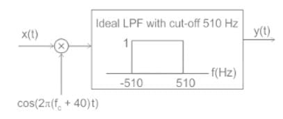
- a)cos(460πt)
- b)cos(920πt)
- c)cos(1000πt)
- d)cos(540πt)
Correct answer is option 'B'. Can you explain this answer?
For the modulated signal x(t) = m(t) cos (2πfct), the message signal m(t) = 4 cos (1000πt) and the carrier frequency fc is 1 MHz. The signal x(t) is passed through a demodulator, as shown in the figure below. The output y(t) of the demodulator is
a)
cos(460πt)
b)
cos(920πt)
c)
cos(1000πt)
d)
cos(540πt)
|
|
Sarita Yadav answered |
Concept: Low pass filter allow the low frequency components ( up to Bandwidth of filter) to pass through it.
Calculation:
x(t) = m(t) cos (2πfct)
m(t) = 4 cos (1000 πt)
The output of the multiplier(s(t)) will be:
s(t) = x(t) cos (2π(fc + 40)t)
s(t) = m(t) cos (2πfct) cos (2π(fc + 40)t)
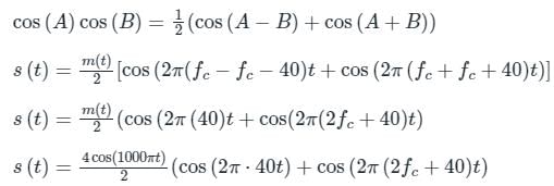
s(t) = 2 cos (100 πt)⋅cos (2π 40t) + 2 cos (1000 πt) cos (2π(2fc + 40)t
Again using the same trigonometric identify, the above equation can be written as:
s(t) = cos (1000πt – 80πt) + cos (1000πt + 80πt) + cos (1000πt – 2π(2fc + 40)t) + cos (1000πt + 2π (2fc + 40)t)
s(t) = cos (920πt) + cos (1080πt) + cos (1000πt – 2π (2fc - 40)t + cos(1000πt + 2π (2fc + 40)t)
The frequency specimen of s(t) can be drawn as:
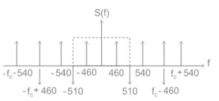
The output of the low pass filter will contain frequencies of 460 Hz only as shown:
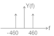
∴ y(t) = cos (920 πt)
The sensitivity of a superheterodyne receiver does not depend on- a)the gain of the RF amplifier
- b)the noise figure of the receiver
- c)the receiving frequency
- d)the gain of the IF amplifier
Correct answer is option 'C'. Can you explain this answer?
The sensitivity of a superheterodyne receiver does not depend on
a)
the gain of the RF amplifier
b)
the noise figure of the receiver
c)
the receiving frequency
d)
the gain of the IF amplifier
|
|
Gaurav Bhandari answered |
Understanding Superheterodyne Receiver Sensitivity
The sensitivity of a superheterodyne receiver refers to its ability to detect weak signals. Several factors influence this sensitivity, but the receiving frequency does not affect it.
Key Factors Influencing Sensitivity:
- Gain of the RF Amplifier:
The gain of the radio frequency (RF) amplifier directly impacts sensitivity. Higher gain amplifies weak signals better, improving the receiver's ability to detect them.
- Noise Figure of the Receiver:
The noise figure measures how much noise the receiver adds to the signal. A lower noise figure enhances sensitivity, allowing weaker signals to be discerned against the noise floor.
- Gain of the IF Amplifier:
The intermediate frequency (IF) amplifier also contributes to sensitivity. Increased gain at this stage amplifies the already processed signals further, making it easier to detect weak inputs.
Receiving Frequency and Sensitivity:
- The receiving frequency itself does not influence sensitivity because it is primarily determined by the characteristics of the amplifiers and the overall design of the receiver.
- While different frequencies might require adjustments in components, the fundamental principles governing sensitivity remain constant, irrespective of the frequency.
Conclusion:
In summary, the sensitivity of a superheterodyne receiver is primarily dictated by the gains of the RF and IF amplifiers and the noise figure. The receiving frequency is an operational parameter but does not inherently affect the receiver's sensitivity to weak signals. Thus, the correct answer is option 'C'.
What will be the upper sideband and lower sideband frequencies for amplitude modulation of a 5-kHz signal with 40-kHz carrier frequency?- a)42.5 kHz and 37.5 kHz, respectively
- b)45 kHz and 35 kHz, respectively
- c)50 kHz and 30 kHz, respectively
- d)25 kHz and 15 kHz, respectively
Correct answer is option 'B'. Can you explain this answer?
What will be the upper sideband and lower sideband frequencies for amplitude modulation of a 5-kHz signal with 40-kHz carrier frequency?
a)
42.5 kHz and 37.5 kHz, respectively
b)
45 kHz and 35 kHz, respectively
c)
50 kHz and 30 kHz, respectively
d)
25 kHz and 15 kHz, respectively
|
|
Gauri Yadav answered |
Introduction:
In amplitude modulation (AM), the information signal is modulated onto a higher frequency carrier signal. This modulation process generates two sidebands, known as the upper sideband (USB) and lower sideband (LSB). The frequencies of these sidebands can be determined using the formula:
Sideband frequencies:
The sideband frequencies are calculated using the formula:
USB = Carrier frequency + Modulating frequency
LSB = Carrier frequency - Modulating frequency
Given data:
Carrier frequency = 40 kHz
Modulating frequency = 5 kHz
Calculations:
Using the given formula, we can calculate the sideband frequencies as follows:
USB = 40 kHz + 5 kHz = 45 kHz
LSB = 40 kHz - 5 kHz = 35 kHz
Therefore, the upper sideband frequency is 45 kHz, and the lower sideband frequency is 35 kHz.
Explanation:
In amplitude modulation, the modulating signal is used to vary the amplitude of the carrier signal. The modulation process generates two sidebands, which are essentially the modulating signal shifted in frequency. The USB is located above the carrier frequency, while the LSB is located below the carrier frequency.
In this case, the carrier frequency is 40 kHz, and the modulating frequency is 5 kHz. We can calculate the sideband frequencies by adding or subtracting the modulating frequency from the carrier frequency.
The USB is obtained by adding the modulating frequency to the carrier frequency:
USB = 40 kHz + 5 kHz = 45 kHz
Similarly, the LSB is obtained by subtracting the modulating frequency from the carrier frequency:
LSB = 40 kHz - 5 kHz = 35 kHz
Therefore, the upper sideband frequency is 45 kHz, and the lower sideband frequency is 35 kHz. This means that the modulating signal will be present at these frequencies when using amplitude modulation with a carrier frequency of 40 kHz and a modulating frequency of 5 kHz.
If the modulation index of an AM wave is changed from 0 to 1, the transmitted power- a)increases by 50%
- b)increases by 75%
- c)increases by 100%
- d)remains unaffected
Correct answer is option 'A'. Can you explain this answer?
If the modulation index of an AM wave is changed from 0 to 1, the transmitted power
a)
increases by 50%
b)
increases by 75%
c)
increases by 100%
d)
remains unaffected
|
|
Neel Desai answered |
Explanation:
When the modulation index of an AM wave is changed from 0 to 1, there is a significant change in the transmitted power. Let's understand this in detail.
Modulation Index:
The modulation index of an AM wave determines the extent of modulation applied to the carrier wave. It is defined as the ratio of the peak amplitude of the modulating signal to the peak amplitude of the carrier wave.
Effect of Modulation Index on Transmitted Power:
When the modulation index is changed from 0 to 1, the transmitted power increases by 50%. This can be explained by considering the power calculation of an AM wave.
Power Calculation:
The power of an AM wave can be calculated as the sum of the carrier power and the sideband powers.
- Carrier Power: The power of the carrier wave is proportional to the square of its amplitude.
- Sideband Power: The power of the sidebands is proportional to the square of their amplitudes.
Effect of Modulation on Carrier and Sidebands:
When the modulation index is 0, there is no modulation applied to the carrier wave. In this case, the carrier wave remains at its original amplitude, and there are no sidebands. Therefore, the transmitted power is solely the power of the carrier wave.
When the modulation index is 1, the modulating signal fully modulates the carrier wave. This results in the generation of two sidebands that carry the information. The amplitude of the carrier wave is varied based on the modulating signal, resulting in an increase in its peak amplitude. As a result, the power of the carrier wave increases.
Additionally, the power of the sidebands is also generated due to modulation. The sidebands have their own power, which adds to the total transmitted power.
Overall Increase in Transmitted Power:
Therefore, when the modulation index is changed from 0 to 1, the power of the carrier wave increases along with the power of the sidebands. This overall increase in power results in a 50% increase in the transmitted power.
Conclusion:
In summary, when the modulation index of an AM wave is changed from 0 to 1, the transmitted power increases by 50%. This is because the modulation fully modulates the carrier wave, increasing its power, and also generates sidebands that contribute to the total power.
Chapter doubts & questions for Amplitude Modulation: Analog Communication - Communication System 2025 is part of Electronics and Communication Engineering (ECE) exam preparation. The chapters have been prepared according to the Electronics and Communication Engineering (ECE) exam syllabus. The Chapter doubts & questions, notes, tests & MCQs are made for Electronics and Communication Engineering (ECE) 2025 Exam. Find important definitions, questions, notes, meanings, examples, exercises, MCQs and online tests here.
Chapter doubts & questions of Amplitude Modulation: Analog Communication - Communication System in English & Hindi are available as part of Electronics and Communication Engineering (ECE) exam.
Download more important topics, notes, lectures and mock test series for Electronics and Communication Engineering (ECE) Exam by signing up for free.
Communication System
14 videos|44 docs|30 tests
|
|
© EduRev
|
Education Revolution
|


|


Signup to see your scores
go up within 7 days!
Access 1000+ FREE Docs, Videos and Tests
Takes less than 10 seconds to signup