


All Exams > Electrical Engineering (EE) > Power Electronics > All Questions
All questions of Three Phase Line Commutated Converter for Electrical Engineering (EE) Exam
A M-6 controlled converter or 6-pulse half-wave controlled converter is obtained by using a transformer having- a)a double delta connected secondary winding
- b)a double star connected secondary winding
- c)a double delta connected primary winding
- d)6-windings on both primary and secondary sides
Correct answer is option 'B'. Can you explain this answer?
A M-6 controlled converter or 6-pulse half-wave controlled converter is obtained by using a transformer having
a)
a double delta connected secondary winding
b)
a double star connected secondary winding
c)
a double delta connected primary winding
d)
6-windings on both primary and secondary sides
| | Sparsh Saini answered |
M-6 requires a transformer having a delta connected primary and a double star connected secondary such that 6 SCRs are connected to it on the secondary side.

In case of a three phase full controlled converter with 6 SCRs, commutation occurs every- a)120°
- b)60°
- c)180°
- d)30°
Correct answer is option 'B'. Can you explain this answer?
In case of a three phase full controlled converter with 6 SCRs, commutation occurs every
a)
120°
b)
60°
c)
180°
d)
30°
| | Kunal Sharma answered |
Every SCR conducts for 120°. This means that the SCRs from the positive group are fired 120° among themselves, same is true for SCRs from negative group. For example, if T1 starts conducting at 90° it will conduct till 90+120 = 210°. But while T1 is conducting, half of the time i.e. from 90 to 150, T6 is conducting and another half of the time T2 is conducting. Hence, commutation (change in the SCR which is conducting) takes place every 60 degrees irrespective of the firing angle. Construct the firing sequence table for better understanding.
A 3-phase full converter delivers a ripple free load current of 10 A with a firing angle delay of 45°. Find the DF (distortion factor).- a)1.414
- b)0
- c)0.707
- d)0.569
Correct answer is option 'C'. Can you explain this answer?
A 3-phase full converter delivers a ripple free load current of 10 A with a firing angle delay of 45°. Find the DF (distortion factor).
a)
1.414
b)
0
c)
0.707
d)
0.569
| | Prasad Saini answered |
The firing angle delay of 45 degrees means that the thyristors in the full converter are triggered to turn on and conduct current after 45 degrees of the input voltage waveform.
To deliver a ripple-free load current of 10 A, the full converter needs to operate in continuous current mode. In this mode, the load current is always positive and never drops to zero.
In a 3-phase full converter, there are 6 thyristors (2 for each phase). Each thyristor conducts for 180 degrees of the input voltage waveform.
With a firing angle delay of 45 degrees, the thyristors will turn on at 45 degrees after the start of each half-cycle of the input voltage waveform. This means that each thyristor conducts for 135 degrees (180 - 45) of each half-cycle.
Therefore, the average load current can be calculated as follows:
Average load current = (conduction time / total time) * peak load current
For a 3-phase full converter, the total time for each half-cycle is 180 degrees.
Conduction time for each thyristor = 135 degrees / 360 degrees (1 cycle) * 180 degrees (1 half-cycle)
Conduction time for all thyristors = 6 * 135 degrees / 360 degrees * 180 degrees
Conduction time for all thyristors = 6 * 0.375 * 180 degrees
Conduction time for all thyristors = 405 degrees
Therefore, the average load current is:
Average load current = (405 degrees / 180 degrees) * peak load current
Average load current = 2.25 * peak load current
To deliver a ripple-free load current of 10 A, the peak load current should be:
Peak load current = 10 A / 2.25
Peak load current = 4.44 A
Therefore, to deliver a ripple-free load current of 10 A with a firing angle delay of 45 degrees, the peak load current should be approximately 4.44 A.
The commutation period when both incoming and outgoing SCRs are conducting due to source inductance is called as the- a)conduction delay
- b)overlap period
- c)one on one period
- d)distorting angle
Correct answer is option 'B'. Can you explain this answer?
The commutation period when both incoming and outgoing SCRs are conducting due to source inductance is called as the
a)
conduction delay
b)
overlap period
c)
one on one period
d)
distorting angle
| | Nikhil Iyer answered |
Due to source inductance, SCRs cannot start and stop conducting immediately, hence a time occurs when both incoming and outgoing SCRs are conducting together. This delay is called as commutation angle or overlap period (μ).
Which of the below mentioned converter can operate in both 3-pulse and 6-pulse modes?- a)3-phase half wave controller
- b)3-phase full converter
- c)3-phase semi-converter
- d)None of the mentioned
Correct answer is option 'C'. Can you explain this answer?
Which of the below mentioned converter can operate in both 3-pulse and 6-pulse modes?
a)
3-phase half wave controller
b)
3-phase full converter
c)
3-phase semi-converter
d)
None of the mentioned
| | Mihir Chawla answered |
Answer:
A 3-phase semi-converter is the converter that can operate in both 3-pulse and 6-pulse modes. Let's understand why this is the correct answer.
Explanation:
1. 3-phase half wave controller:
A 3-phase half wave controller is a single-phase controlled rectifier used for converting AC voltage to DC voltage. It can only operate in half-wave mode and cannot be used in both 3-pulse and 6-pulse modes. Therefore, option 'a' is incorrect.
2. 3-phase full converter:
A 3-phase full converter is a six-pulse converter that converts AC voltage to DC voltage. It operates by using six thyristors in a bridge configuration. It cannot operate in both 3-pulse and 6-pulse modes simultaneously. Therefore, option 'b' is incorrect.
3. 3-phase semi-converter:
A 3-phase semi-converter is a converter that can operate in both 3-pulse and 6-pulse modes. It consists of three thyristors connected in a bridge configuration. In the 3-pulse mode, only one thyristor conducts during each half-cycle of the input AC waveform, resulting in a 3-pulse output. In the 6-pulse mode, two thyristors conduct during each half-cycle, resulting in a 6-pulse output. The mode of operation can be switched by controlling the firing angles of the thyristors. Therefore, option 'c' is correct.
4. None of the mentioned:
This option is incorrect as a 3-phase semi-converter can operate in both 3-pulse and 6-pulse modes.
Therefore, the correct answer is option 'C' - 3-phase semi-converter.
In a p-pulse converter, each SCR conducts for (per cycle)- a)p radians
- b)p degrees
- c)p/2π radians
- d)2π/p radians
Correct answer is option 'D'. Can you explain this answer?
In a p-pulse converter, each SCR conducts for (per cycle)
a)
p radians
b)
p degrees
c)
p/2π radians
d)
2π/p radians
| | Nitya Chopra answered |
In a p-pulse controlled converter, each device conducts for p radians. p-pulse converter would have p devices. Hence, 2π/p x p = 2π = 360°.
A three-phase full converter charges a battery from a three-phase supply of 230 V. Find the value of the power delivered to the load if a continues current of 20A is flowing through the battery of emf 200 V and internal resistance of 0.5 Ω.- a)0 W
- b)5600 W
- c)4200 W
- d)1040 W
Correct answer is option 'C'. Can you explain this answer?
A three-phase full converter charges a battery from a three-phase supply of 230 V. Find the value of the power delivered to the load if a continues current of 20A is flowing through the battery of emf 200 V and internal resistance of 0.5 Ω.
a)
0 W
b)
5600 W
c)
4200 W
d)
1040 W
| | Nandita Kulkarni answered |
Iavg = Irms = 20 A
P = E x Iavg + Irms2 x R = 4200 W.
P = E x Iavg + Irms2 x R = 4200 W.
A three-phase M-3 converter is operated from a 3-phase, 230 V, 50 Hz supply with load resistance R = 10 Ω. Find the value of firing angle if an average output voltage of 50% of the maximum possible output voltage is required.Hint: α > 30°.- a)92.7°
- b)67.7°
- c)45°
- d)75.7°
Correct answer is option 'B'. Can you explain this answer?
A three-phase M-3 converter is operated from a 3-phase, 230 V, 50 Hz supply with load resistance R = 10 Ω. Find the value of firing angle if an average output voltage of 50% of the maximum possible output voltage is required.Hint: α > 30°.
a)
92.7°
b)
67.7°
c)
45°
d)
75.7°
| | Aniket Shah answered |
We need , Vo = 0.5 Vom.
α>30° hence we use the equation Vo = (3√3/2π) x Vmp x [1+cos(30+α)] √3Vmp = Vml = √2×230
Therefore, Vo = (3/2π) x √3 Vml x [1+cos(30+α)] = 0.5Vom
(1/√3) x [1+cos(30+α)] = Vo x 2π/3Vml = Vo/Vom = 1/2
α = 67.7°.
α>30° hence we use the equation Vo = (3√3/2π) x Vmp x [1+cos(30+α)] √3Vmp = Vml = √2×230
Therefore, Vo = (3/2π) x √3 Vml x [1+cos(30+α)] = 0.5Vom
(1/√3) x [1+cos(30+α)] = Vo x 2π/3Vml = Vo/Vom = 1/2
α = 67.7°.
Semi-converters are- a)single quadrant converters
- b)double quadrant converters
- c)three quadrant converters
- d)none of the mentioned
Correct answer is option 'A'. Can you explain this answer?
Semi-converters are
a)
single quadrant converters
b)
double quadrant converters
c)
three quadrant converters
d)
none of the mentioned
| | Sandeep Saha answered |
Single Quadrant Converters
Single quadrant converters are a type of semi-converters that operate in a single quadrant of the input-output plane. They are capable of converting AC voltage or current into DC voltage or current in one direction only. They are also known as half-wave rectifiers.
Working Principle
The working principle of single quadrant converters is based on the fact that a diode conducts current in one direction only. During the positive half-cycle of the input AC voltage, the diode conducts and allows the flow of current through the load. During the negative half-cycle, the diode blocks the flow of current, and no current flows through the load.
Applications
Single quadrant converters are widely used in applications where unidirectional power flow is required, such as battery charging, electroplating, and DC motor control.
Advantages
- Simple and low-cost circuit design
- Easy to implement
- Low power losses
Disadvantages
- Only suitable for unidirectional power flow
- Low efficiency due to the use of a single diode
- Produces harmonic distortion in the output waveform
Conclusion
Single quadrant converters are simple and cost-effective solutions for converting AC voltage or current into DC voltage or current in one direction only. They are widely used in various applications and offer several advantages, including easy implementation and low power losses. However, they also have some limitations, such as low efficiency and harmonic distortion in the output waveform.
A three-phase half-wave controlled converter is fed from a 3-phase, 400 V source and is connected to a load which takes a constant current of 36 A. Find,the value of average output voltage and average current rating of SCR for a firing angle of 30°.- a)234 V, 36 A
- b)234 V, 12 A
- c)135 V, 36 A
- d)135 V, 12 A
Correct answer is option 'B'. Can you explain this answer?
A three-phase half-wave controlled converter is fed from a 3-phase, 400 V source and is connected to a load which takes a constant current of 36 A. Find,the value of average output voltage and average current rating of SCR for a firing angle of 30°.
a)
234 V, 36 A
b)
234 V, 12 A
c)
135 V, 36 A
d)
135 V, 12 A
| | Sparsh Nambiar answered |
Vo = (3√3/2π) x Vmp x cosα = 233.874 V.
Ia = Io/3 = 12 A.
Ia = Io/3 = 12 A.
Which of the following converter circuits would require a neutral point?- a)3-phase semi-converter
- b)3-phase full converter
- c)3-phase full converter with freewheeling diode
- d)3-phase half wave converter
Correct answer is option 'D'. Can you explain this answer?
Which of the following converter circuits would require a neutral point?
a)
3-phase semi-converter
b)
3-phase full converter
c)
3-phase full converter with freewheeling diode
d)
3-phase half wave converter
| | Tanishq Chauhan answered |
Half wave converter would require delta-star transformer, the secondary winding star connection requires a neutral point.
A three-phase, three-pulse, M-3 type controlled converter uses ____________ number of SCRs.- a)1
- b)2
- c)3
- d)4
Correct answer is option 'C'. Can you explain this answer?
A three-phase, three-pulse, M-3 type controlled converter uses ____________ number of SCRs.
a)
1
b)
2
c)
3
d)
4
| | Suyash Joshi answered |
It uses three SCRs with a three-phase transformer. M-3 type 3-pulse converters are not practically used.
A 3-phase full converter feeds power to an R load of 10 Ω. For a firing angle delay of 30° the load takes 5 kW. An inductor of large value is also connected to the load to make the current ripple free. Find the value of per phase input voltage.- a)133 V
- b)230/√3 V
- c)191/√3 V
- d)298/√3 V
Correct answer is option 'C'. Can you explain this answer?
A 3-phase full converter feeds power to an R load of 10 Ω. For a firing angle delay of 30° the load takes 5 kW. An inductor of large value is also connected to the load to make the current ripple free. Find the value of per phase input voltage.
a)
133 V
b)
230/√3 V
c)
191/√3 V
d)
298/√3 V
| | Arpita Banerjee answered |
Ior = Vo/R = (3Vml/Rπ) cos α
P = 5 kW = Ior2 x R = [(3Vml/π) cos α]2 x 1/R] Therefore, Vs (line) = √50000 x (π/√2 x 3 x cos30) = 191.22 V
Vs (phase) = 191/√3 V.
P = 5 kW = Ior2 x R = [(3Vml/π) cos α]2 x 1/R] Therefore, Vs (line) = √50000 x (π/√2 x 3 x cos30) = 191.22 V
Vs (phase) = 191/√3 V.
What is the relationship between DF, CDF and PF?- a)PF = CDF = DF
- b)PF = CDF/DF
- c)PF = DF/CDF
- d)PF = CDF x DF
Correct answer is option 'D'. Can you explain this answer?
What is the relationship between DF, CDF and PF?
a)
PF = CDF = DF
b)
PF = CDF/DF
c)
PF = DF/CDF
d)
PF = CDF x DF
| | Bijoy Mehta answered |
PF (power factor) = (distortion factor) x (current distortion factor).
In a 3 phase M-6 controlled converter for continuous conduction mode, each SCR conducts for __________ per cycle.- a)2π/6 radians
- b)30 degrees
- c)3π/2 radians
- d)120 degrees
Correct answer is option 'A'. Can you explain this answer?
In a 3 phase M-6 controlled converter for continuous conduction mode, each SCR conducts for __________ per cycle.
a)
2π/6 radians
b)
30 degrees
c)
3π/2 radians
d)
120 degrees
| | Aditya Basu answered |
Each SCR conducts for 60° or 2π/6 radians. 6 x 60 = 360°.
The range of firing angle for a 3-phase, 3-pulse converter feeding a resistive load is __________ (in degrees).- a)0 to 180
- b)0 to 150
- c)30 to 150
- d)30 to 180
Correct answer is option 'B'. Can you explain this answer?
The range of firing angle for a 3-phase, 3-pulse converter feeding a resistive load is __________ (in degrees).
a)
0 to 180
b)
0 to 150
c)
30 to 150
d)
30 to 180
| | Mainak Roy answered |
Range of Firing Angle for a 3-phase, 3-pulse Converter
To determine the range of firing angles for a 3-phase, 3-pulse converter feeding a resistive load, we need to consider the operation of the converter and the limitations imposed by the system.
Operation of a 3-phase, 3-pulse Converter
- A 3-phase, 3-pulse converter is a type of rectifier that converts AC power into DC power.
- It consists of three diodes connected in a bridge configuration, with each diode connected to one phase of the AC supply.
- The converter operates by turning on the diodes in a specific sequence to rectify the AC voltage into a pulsating DC voltage.
- The firing angle determines the delay between the AC voltage waveform and the turning on of the diodes.
Limitations and Constraints
- For a resistive load, the converter should operate in the continuous conduction mode to ensure a smooth DC output voltage.
- In the continuous conduction mode, the diodes should not turn off during the conduction period of the AC waveforms.
- The firing angle should be chosen such that the diodes remain conducting until the next phase is turned on.
- The maximum firing angle is limited by the requirement that the diodes should not turn off before the next phase is turned on.
Determining the Range of Firing Angle
- In a 3-pulse converter, each phase is turned on for 120 degrees of the AC cycle.
- The firing angle for each phase can be defined as the delay in turning on the diodes with respect to the AC voltage waveform.
- The minimum firing angle is 0 degrees, where the diodes turn on immediately at the start of each phase.
- The maximum firing angle is limited by the condition that the diodes should not turn off before the next phase is turned on.
- Since each phase is turned on for 120 degrees, the diodes should remain conducting for at least 120 degrees to ensure continuous conduction.
- Therefore, the maximum firing angle is 150 degrees, allowing a 30-degree safety margin to ensure continuous conduction.
Conclusion
The range of firing angle for a 3-phase, 3-pulse converter feeding a resistive load is 0 to 150 degrees. This range ensures continuous conduction and prevents the diodes from turning off before the next phase is turned on.
A three-phase three-pulse converter would operate as a line commutated inverter when- a)30° < α < 60°
- b)90° < α <180°
- c)90° > α
- d)it can never operate as a line commutated inverter
Correct answer is option 'B'. Can you explain this answer?
A three-phase three-pulse converter would operate as a line commutated inverter when
a)
30° < α < 60°
b)
90° < α <180°
c)
90° > α
d)
it can never operate as a line commutated inverter
| | Harshitha Pillai answered |
A) The converter is supplied with three-phase AC voltage and the thyristors are triggered in a specific sequence to convert the input AC voltage into a variable frequency AC output voltage.
A 3-phase bridge converter is given a three-phase supply in the phase sequence R-Y-B. Let the neutral to R phase voltage be Vm sinωt. The first SCR (connected to R phase) is fired at an angle of 15°. What is the maximum value at the output terminals at this instant?- a)Vm/√2
- b)Vm
- c)1.5 Vm
- d)3 Vm
Correct answer is option 'C'. Can you explain this answer?
A 3-phase bridge converter is given a three-phase supply in the phase sequence R-Y-B. Let the neutral to R phase voltage be Vm sinωt. The first SCR (connected to R phase) is fired at an angle of 15°. What is the maximum value at the output terminals at this instant?
a)
Vm/√2
b)
Vm
c)
1.5 Vm
d)
3 Vm
| | Alok Khanna answered |
In case of a 3 phase bridge converter, the maximum value of voltage at the output terminal is always 1.5 Vm.
A three-phase semi-converter circuit is given a supply of 400 V. It produces at the output terminals an average voltage of 381 V. Find the rectification efficiency of the converter circuit.- a)99.65 %
- b)95.25 %
- c)91 %
- d)86.5 %
Correct answer is option 'B'. Can you explain this answer?
A three-phase semi-converter circuit is given a supply of 400 V. It produces at the output terminals an average voltage of 381 V. Find the rectification efficiency of the converter circuit.
a)
99.65 %
b)
95.25 %
c)
91 %
d)
86.5 %
| | Aaditya Choudhary answered |
Rectification efficiency = Pdc/Pac
Pdc = Vo x Io . . . (both average values of output current and voltage)
Pac = Vrms x Irms . . . (both rms values of input current and voltage)
For a semi-converter Irms = Io
Therefore, Rectification efficiency = 381/400 = 95.25 %.
Pdc = Vo x Io . . . (both average values of output current and voltage)
Pac = Vrms x Irms . . . (both rms values of input current and voltage)
For a semi-converter Irms = Io
Therefore, Rectification efficiency = 381/400 = 95.25 %.
A three-phase full converter supplied from a 230 V source is working as a line commutated inverter. The load consists of RLE type with R = 5 Ω, E = 200 V and L = 1 mH. A continues current of 10 A is flowing through the load, find the value of the firing angle delay.- a)119°
- b)127°
- c)156°
- d)143°
Correct answer is option 'A'. Can you explain this answer?
A three-phase full converter supplied from a 230 V source is working as a line commutated inverter. The load consists of RLE type with R = 5 Ω, E = 200 V and L = 1 mH. A continues current of 10 A is flowing through the load, find the value of the firing angle delay.
a)
119°
b)
127°
c)
156°
d)
143°
| | Siddharth Khanna answered |
Vo = 200 – 10×5 = 150V as the circuit is operating as an inverter Vo = -150V
Now, Vo = (3Vml/π) cos α
α = cos-1(-150π/3√2×230) = 118.88°.
Now, Vo = (3Vml/π) cos α
α = cos-1(-150π/3√2×230) = 118.88°.
A three-phase full converter charges a battery from a three-phase supply of 230 V. The battery emf is 200 V. Find the value of the firing angle if the battery terminal voltage is 210 V.- a)36.54°
- b)56.7°
- c)89.3°
- d)47.45°
Correct answer is option 'D'. Can you explain this answer?
A three-phase full converter charges a battery from a three-phase supply of 230 V. The battery emf is 200 V. Find the value of the firing angle if the battery terminal voltage is 210 V.
a)
36.54°
b)
56.7°
c)
89.3°
d)
47.45°
| | Hrishikesh Yadav answered |
Vo = (3Vml/π) cos α
α = cos-1(210π/3√2×230) = 47.453°.
α = cos-1(210π/3√2×230) = 47.453°.
The effect of source inductance on the performance of a 3-phase controlled converter is to- a)increase the average load voltage
- b)reduce the average load voltage
- c)make the load current continuous
- d)remove ripples from the load current
Correct answer is option 'B'. Can you explain this answer?
The effect of source inductance on the performance of a 3-phase controlled converter is to
a)
increase the average load voltage
b)
reduce the average load voltage
c)
make the load current continuous
d)
remove ripples from the load current
| | Anshika Nambiar answered |
Effect of Source Inductance on the Performance of a 3-Phase Controlled Converter
Introduction:
A 3-phase controlled converter is a power electronic device used to convert AC power to DC power. It consists of a rectifier circuit that converts the input AC voltage to a pulsating DC voltage, which is then filtered to obtain a smooth DC output voltage. The performance of a controlled converter is influenced by various factors, one of which is the source inductance.
Explanation:
The source inductance refers to the inductance present in the AC power supply connected to the controlled converter. It can be in the form of line inductance or the inductance of the power transformer. The presence of source inductance affects the operation of the controlled converter in several ways.
1. Reduction in Average Load Voltage:
The presence of source inductance causes a voltage drop across it due to the current flowing through it. This voltage drop reduces the available voltage at the input of the controlled converter, leading to a decrease in the average load voltage. As a result, the output voltage of the converter will be lower than expected.
2. Continuity of Load Current:
The source inductance helps in maintaining the continuity of the load current. The inductance stores energy during the periods of high input voltage and releases it during the periods of low input voltage. This energy storage and release mechanism helps in reducing the fluctuations in the load current, making it more continuous.
3. Ripples in Load Current:
The presence of source inductance in the controlled converter also helps in reducing the ripples in the load current. The inductance smooths out the variations in the input voltage and helps in maintaining a relatively constant load current. This is especially beneficial in applications where a steady and continuous load current is required.
Conclusion:
In conclusion, the presence of source inductance in a 3-phase controlled converter has a significant impact on its performance. It reduces the average load voltage, helps in maintaining the continuity of the load current, and reduces the ripples in the load current. Therefore, the correct answer to the given question is option 'B' - source inductance reduces the average load voltage.
In a three-phase semi-converter, at a time one SCR and one diode conduct simultaneously. With SCR T1 conducting which diode(s) is most likely to conduct along with T1?
- a)D2 only
- b)D3 only
- c)D1 and D2
- d)D2 and D3
Correct answer is option 'D'. Can you explain this answer?
In a three-phase semi-converter, at a time one SCR and one diode conduct simultaneously. With SCR T1 conducting which diode(s) is most likely to conduct along with T1?
a)
D2 only
b)
D3 only
c)
D1 and D2
d)
D2 and D3
| | Ayush Kumar answered |
T1 and D1 together will cause a S.C. D2 or D3 any of these two can conduct along with T1 depending on which phase voltage is currently active RB or RY.
A three phase six pulse full converter works as a ac to dc converter for firing angles in the range- a)α > 90
- b)90 < α < 180
- c)0 < α < 90
- d)0 < α < 360
Correct answer is option 'C'. Can you explain this answer?
A three phase six pulse full converter works as a ac to dc converter for firing angles in the range
a)
α > 90
b)
90 < α < 180
c)
0 < α < 90
d)
0 < α < 360
| | Raj Desai answered |
When α is less than 90°, the SCRs conduct for 120° and the current and voltage are positive on an average hence, the power flows from AC source to DC load.
A three-phase, three-pulse, M-3 type controlled converter has firing angle for one of the SCRs set as 15°. This SCR would start conducting at- a)0°
- b)15°
- c)30°
- d)45°
Correct answer is option 'D'. Can you explain this answer?
A three-phase, three-pulse, M-3 type controlled converter has firing angle for one of the SCRs set as 15°. This SCR would start conducting at
a)
0°
b)
15°
c)
30°
d)
45°
| | Raj Desai answered |
In a three phase controller, the actually conduction starts at 30° + α. Hence, ωt = 30+15 = 45°.
In a 3 phase, 12-pulse controlled converter for continuous conduction mode, each SCR conducts for __________ per cycle.- a)π/6 radians
- b)60 degrees
- c)3π/2 radians
- d)12 degrees
Correct answer is option 'A'. Can you explain this answer?
In a 3 phase, 12-pulse controlled converter for continuous conduction mode, each SCR conducts for __________ per cycle.
a)
π/6 radians
b)
60 degrees
c)
3π/2 radians
d)
12 degrees
| | Gargi Basak answered |
Each SCR conducts for 30° or π/6 radians. 12 x 30 = 360°.
A three-phase three pulse type controlled converter is constructed using 3 SCR devices. The circuit is supplying an R load with α < 30°. As such, each SCR device would conduct for- a)60° each cycle
- b)120° each cycle
- c)180° each cycle
- d)360° each cycle
Correct answer is option 'B'. Can you explain this answer?
A three-phase three pulse type controlled converter is constructed using 3 SCR devices. The circuit is supplying an R load with α < 30°. As such, each SCR device would conduct for
a)
60° each cycle
b)
120° each cycle
c)
180° each cycle
d)
360° each cycle
| | Mahesh Singh answered |
Each conduct for 120° per cycle is the firing angle is less than 30°. 120 x 3 = 360°.
A three phase full converter will require __________ number of SCRs.- a)3
- b)6
- c)9
- d)2
Correct answer is option 'B'. Can you explain this answer?
A three phase full converter will require __________ number of SCRs.
a)
3
b)
6
c)
9
d)
2
| | Shail Nambiar answered |
Three legs having two SCRs each, six in total.
For a three phase full controlled converter, with 3 thyristors in the upper or positive group and 3 thyristors in the lower or negative group, at any given time- a)two thyristors are conducting from each group
- b)one thyristor is conducting from each group
- c)one thyristor is conducting from either of the groups
- d)all 6 thyristors are conducting at a time
Correct answer is option 'B'. Can you explain this answer?
For a three phase full controlled converter, with 3 thyristors in the upper or positive group and 3 thyristors in the lower or negative group, at any given time
a)
two thyristors are conducting from each group
b)
one thyristor is conducting from each group
c)
one thyristor is conducting from either of the groups
d)
all 6 thyristors are conducting at a time
| | Raghav Nambiar answered |
Let’s say T1, T3 and T5 belong to the positive group and T2, T4 and T6 to the negative group. At any given time one SCR from each group conducts. e.g. T1 and T6 or T1 and T2.
In a 3-phase semi-converter, for firing angle less than 60° the freewheeling diode conducts for- a)30°
- b)60°
- c)120°
- d)0
Correct answer is option 'D'. Can you explain this answer?
In a 3-phase semi-converter, for firing angle less than 60° the freewheeling diode conducts for
a)
30°
b)
60°
c)
120°
d)
0
| | Om Saini answered |
In case of a semi-converter operating with α < 60°, FD does not comes into play, as the voltage never falls to zero and gives no chance for the inductor to discharge.
In a three-phase, three-pulse, M-3 type controlled converter T1 starts to conduct at 30 + n°. At what angles do T2 and T3 start to conduct? Assume that the conduction sequence is T1-T2-T3.- a)2n° and 3n°
- b)150 + n° and 270 + n°
- c)n° each
- d)30 + n° and 60 + n°
Correct answer is option 'B'. Can you explain this answer?
In a three-phase, three-pulse, M-3 type controlled converter T1 starts to conduct at 30 + n°. At what angles do T2 and T3 start to conduct? Assume that the conduction sequence is T1-T2-T3.
a)
2n° and 3n°
b)
150 + n° and 270 + n°
c)
n° each
d)
30 + n° and 60 + n°
| | Athul Banerjee answered |
In three-phase three pulse converter the conduction can start only after 30°. As each SCR conducts from 120°, T2 would conduct on 30+120+n° = 150+n° and so on.
The PIV experienced by each SCRs in M-3 converter is __________ times that in a 3-phase full converter having the same output voltage.- a)0.5
- b)1
- c)2
- d)1.5
Correct answer is option 'C'. Can you explain this answer?
The PIV experienced by each SCRs in M-3 converter is __________ times that in a 3-phase full converter having the same output voltage.
a)
0.5
b)
1
c)
2
d)
1.5
| | Prasad Verma answered |
Explanation:
To understand why the correct answer is option C, let's first define some terms and concepts.
PIV (Peak Inverse Voltage):
PIV is the maximum voltage that an SCR (Silicon Controlled Rectifier) can withstand in the reverse bias direction without breakdown. It is an important parameter to consider when designing and operating SCR-based converters.
M-3 Converter:
An M-3 converter is a three-phase converter that uses three SCRs in parallel in each phase to control the flow of current. The SCRs are connected in a manner that allows them to conduct current in alternating half-cycles of the input voltage.
3-Phase Full Converter:
A three-phase full converter is another type of converter that uses six SCRs to control the flow of current in each phase. The SCRs are connected in a bridge configuration, allowing them to conduct current in both half-cycles of the input voltage.
Now let's analyze the given statement: "The PIV experienced by each SCR in an M-3 converter is __________ times that in a 3-phase full converter having the same output voltage."
Key Points:
- M-3 converter uses three SCRs in parallel in each phase.
- 3-phase full converter uses six SCRs in a bridge configuration.
- Both converters have the same output voltage.
Explanation:
1. In an M-3 converter, each SCR in each phase carries one-third of the total current.
2. Therefore, the PIV experienced by each SCR in an M-3 converter is one-third of the total PIV.
3. In a 3-phase full converter, each SCR in each phase carries the total current.
4. Therefore, the PIV experienced by each SCR in a 3-phase full converter is the total PIV.
5. Since the output voltage is the same for both converters, the total PIV is also the same.
6. Therefore, the PIV experienced by each SCR in an M-3 converter is one-third of the PIV experienced by each SCR in a 3-phase full converter.
7. Mathematically, this can be expressed as:
PIV in M-3 converter = 1/3 * PIV in 3-phase full converter
8. Simplifying the equation gives:
PIV in M-3 converter = (1/3) * PIV in 3-phase full converter = 1/3 * 3 = 1
9. Therefore, the correct answer is option C: 2. The PIV experienced by each SCR in an M-3 converter is 2 times that in a 3-phase full converter having the same output voltage.
Conclusion:
The PIV experienced by each SCR in an M-3 converter is twice the PIV experienced by each SCR in a 3-phase full converter having the same output voltage.
A three-phase full converter charges a battery from a three-phase supply of 230 V. The battery emf is 200 V and the internal resistance of the battery is 0.5 Ω. Find the value of the continuous current which is flowing through the battery if its terminal voltage is 210 V- a)10 A
- b)20 A
- c)0.5 A
- d)25 A
Correct answer is option 'B'. Can you explain this answer?
A three-phase full converter charges a battery from a three-phase supply of 230 V. The battery emf is 200 V and the internal resistance of the battery is 0.5 Ω. Find the value of the continuous current which is flowing through the battery if its terminal voltage is 210 V
a)
10 A
b)
20 A
c)
0.5 A
d)
25 A
| | Rajesh Kumar answered |
Vo = 210 V
Vo = E + Io x R
210 = 200 + 0.5 x Io
Io (Current through the battery) = 20 A.
Vo = E + Io x R
210 = 200 + 0.5 x Io
Io (Current through the battery) = 20 A.
In a 3-phase semi-converter, firing angle is less than 60°, as such each SCR and diode conduct respectively for __________ (in degrees)- a)60, 60
- b)90, 30
- c)120, 120
- d)180, 180
Correct answer is option 'C'. Can you explain this answer?
In a 3-phase semi-converter, firing angle is less than 60°, as such each SCR and diode conduct respectively for __________ (in degrees)
a)
60, 60
b)
90, 30
c)
120, 120
d)
180, 180
| | Raghav Majumdar answered |
Each will conduct for 120° per cycle whatever the firing angle is.
A three-phase full converter is driving a DC motor. If a continues current of Im amperes is flowing through the motor load, then find the rms value of supply current drawn by the converter to drive the motor.- a)Im/√2
- b)Im2/3
- c)√2Im/√3
- d)√2Im/3
Correct answer is option 'C'. Can you explain this answer?
A three-phase full converter is driving a DC motor. If a continues current of Im amperes is flowing through the motor load, then find the rms value of supply current drawn by the converter to drive the motor.
a)
Im/√2
b)
Im2/3
c)
√2Im/√3
d)
√2Im/3
| | Shivam Das answered |
The RMS value of the supply current IS over π radians would be
(IS)2 = (1/π) x (Im)2 x (2π/3) = Im√2/√3.
(IS)2 = (1/π) x (Im)2 x (2π/3) = Im√2/√3.
Each SCR of a 3-phase 6-pulse converter conducts for- a)120 degrees
- b)60 degrees
- c)180 degrees
- d)360 degrees
Correct answer is option 'A'. Can you explain this answer?
Each SCR of a 3-phase 6-pulse converter conducts for
a)
120 degrees
b)
60 degrees
c)
180 degrees
d)
360 degrees
| | Rounak Rane answered |
A 3-phase 6-pulse converter is nothing but the 3-pulse full controlled converter using 6 devices each conducting for 120°.
For a three-phase full controlled converter with R load, the average value of output voltage is zero for- a)α = 0°
- b)α = 90°
- c)α = 180°
- d)It can never be zero
Correct answer is option 'B'. Can you explain this answer?
For a three-phase full controlled converter with R load, the average value of output voltage is zero for
a)
α = 0°
b)
α = 90°
c)
α = 180°
d)
It can never be zero
| | Vaibhav Joshi answered |
For α = 90 degrees, the voltage waveform is equally symmetrical about the ωt axis, hence the average value is zero. This can also be found by using the formula for average output voltage,
Vo = (3Vml/π) cos α,
For α = 90°, cosα = 0, Vo = zero.
Vo = (3Vml/π) cos α,
For α = 90°, cosα = 0, Vo = zero.
A 3-phase full converter has an average output voltage of 365 V for zero degree firing and resistive load. For a firing angle of 90 degree, the output voltage would be- a)125 V
- b)569 V
- c)365 V
- d)zero
Correct answer is option 'D'. Can you explain this answer?
A 3-phase full converter has an average output voltage of 365 V for zero degree firing and resistive load. For a firing angle of 90 degree, the output voltage would be
a)
125 V
b)
569 V
c)
365 V
d)
zero
| | Akanksha Chopra answered |
Full Converter and Firing Angle
Full converter is a type of AC to DC converter that converts the entire AC input voltage into DC output voltage. It uses thyristor as a switching element to control the voltage output. The firing angle is the delay period between the triggering of the thyristor and the point at which the thyristor conducts the current.
Average Output Voltage of Full Converter
The average output voltage of a full converter with a resistive load can be calculated as follows:
Vdc = (2/π)*Vm*cos(α/2)
where Vdc is the DC output voltage, Vm is the peak value of the AC input voltage, and α is the firing angle.
For zero degree firing, α=0, and the output voltage is:
Vdc = (2/π)*Vm*cos(α/2) = (2/π)*Vm*cos(0/2) = (2/π)*Vm = 0.637*Vm
So, if the average output voltage is 365 V for zero degree firing, then the peak value of the AC input voltage is:
Vm = 365/0.637 = 573.7 V
Output Voltage for 90 Degree Firing
For a firing angle of 90 degree, α=90, and the output voltage is:
Vdc = (2/π)*Vm*cos(α/2) = (2/π)*Vm*cos(90/2) = 0
So, the output voltage for 90 degree firing is zero.
Conclusion
The average output voltage of a full converter with a resistive load can be calculated using the formula Vdc = (2/π)*Vm*cos(α/2). For zero degree firing, the output voltage is 0.637*Vm. For a firing angle of 90 degree, the output voltage is zero.
A 3-phase full converter delivers a ripple free load current of 10 A with a firing angle delay of 45°. The input voltage is 3-phase, 400 V, 50 Hz. The source current is given by the following relation.
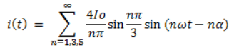
Find the fundamental component of the source current amplitude.- a)11.03
- b)2.205
- c)11.03 sin 45
- d)46.98
Correct answer is option 'A'. Can you explain this answer?
A 3-phase full converter delivers a ripple free load current of 10 A with a firing angle delay of 45°. The input voltage is 3-phase, 400 V, 50 Hz. The source current is given by the following relation.
Find the fundamental component of the source current amplitude.
Find the fundamental component of the source current amplitude.
a)
11.03
b)
2.205
c)
11.03 sin 45
d)
46.98
| | Snehal Rane answered |
Put n = 1 (fundamental component) and the rest of the given values in the above given equation.
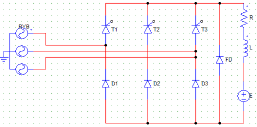
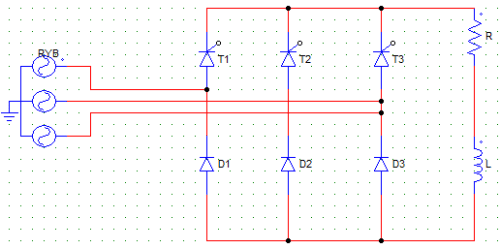
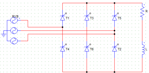
For the below given circuit, the conduction sequence for the negative group of SCRs is

- a)T4-T6-T2
- b)T1-T2-T3
- c)T2-T6-1
- d)T2-T4-T6
Correct answer is option 'D'. Can you explain this answer?
For the below given circuit, the conduction sequence for the negative group of SCRs is
a)
T4-T6-T2
b)
T1-T2-T3
c)
T2-T6-1
d)
T2-T4-T6
| | Ashutosh Majumdar answered |
The negative group of SCRs has T2, T4 and T6. The conduct as T2-T4-T6, as T2 is connected to the B phase, T4 to the R phase and like-wise.
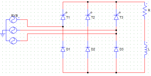
In the below given circuit, each SCR and diode conduct for
- a)60° and 120° respectively
- b)120° and 60° respectively
- c)120°
- d)60°
Correct answer is option 'C'. Can you explain this answer?
In the below given circuit, each SCR and diode conduct for
a)
60° and 120° respectively
b)
120° and 60° respectively
c)
120°
d)
60°
| | Mahesh Datta answered |
At any given time, one SCR and one diode is conducting, each conduct for 120° per cycle.
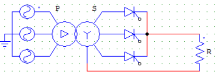
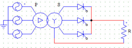
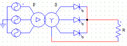
Find the expression for average output voltage at R for the below given configuration. Take firing angle as α = 15°, transformer ratio as 1:1:1 and Vmp as the maximum value of phase voltage at the supply.
- a)(3Vmp/2π) x cosα
- b)(3√3Vmp/2π) x cosα
- c)(3√3Vmp/2π) x sinα
- d)(3Vmp/2π) x sinα
Correct answer is option 'B'. Can you explain this answer?
Find the expression for average output voltage at R for the below given configuration. Take firing angle as α = 15°, transformer ratio as 1:1:1 and Vmp as the maximum value of phase voltage at the supply.
a)
(3Vmp/2π) x cosα
b)
(3√3Vmp/2π) x cosα
c)
(3√3Vmp/2π) x sinα
d)
(3Vmp/2π) x sinα
| | Nilanjan Saini answered |
The circuit is that of a three-pulse M-3 connection. The firing angle is less than 30°. Therefore, each device conducts for an angle of 120°.
Vo = 3 x [ 1/2π ∫ Vmp sinωt d(ωt) ] Where, the integration runs from α+π/6 to α+5π/6.
Vo = (3√3/2π) x Vmp x cosα.
Vo = 3 x [ 1/2π ∫ Vmp sinωt d(ωt) ] Where, the integration runs from α+π/6 to α+5π/6.
Vo = (3√3/2π) x Vmp x cosα.
Name the below given circuit.
- a)Full controlled, bridge converter
- b)Full controlled, semi converter
- c)Bridge type semi-converter
- d)Half controlled, full converter
Correct answer is option 'C'. Can you explain this answer?
Name the below given circuit.
a)
Full controlled, bridge converter
b)
Full controlled, semi converter
c)
Bridge type semi-converter
d)
Half controlled, full converter
| | Om Saini answered |
It uses 3 SCRs and 3 diodes, hence it is a semi-converter. Option (b) and (d) make no sense, because there can be no full controlled semi-converter.
For the below given circuit, α = 60°. T2 will start conduction at ωt = __________ Assume the inductor L value to be negligible.
- a)60°
- b)120°
- c)90°
- d)150°
Correct answer is option 'D'. Can you explain this answer?
For the below given circuit, α = 60°. T2 will start conduction at ωt = __________ Assume the inductor L value to be negligible.
a)
60°
b)
120°
c)
90°
d)
150°
| | Krish Saini answered |
Assuming the phase sequence is R-Y-B. T1 would start conducting at 30+60 = 90°, T2 at 90+210/2 = 150°. This is because after T1, T3 would conduct from the upper group, as T2 belongs to the lower group it will start to conduct exactly between T1 and T3 i.e. between 90 and 210(90+120) which is 150°.
In the below given circuit, __ and __ conduct along with T2.
- a)T1, T3
- b)D1, D2
- c)D1, D3
- d)T1, T2
Correct answer is option 'C'. Can you explain this answer?
In the below given circuit, __ and __ conduct along with T2.
a)
T1, T3
b)
D1, D2
c)
D1, D3
d)
T1, T2
| | Prasenjit Yadav answered |
When one SCR conducts, a diode conducts along with it at a time to provide the path of current flow. . For example, if T2 starts conducting at 90° it will conduct till 90+120 = 210°. But while T2 is conducting, half of the time i.e. from 90 to 150 D1 is conducting and another half of the time D3 is conducting. T2 and D2 cannot conduct together as it will cause a short circuit. Hence, T2-D1 conduct for 60° and then T2-D3 conduct for another 60°.
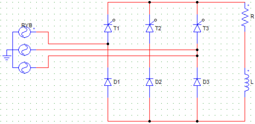
In the circuit shown below, SCR T1 conducts first. If T1 is fired at an angle of α > 30°, then T1 would conduct from
- a)α to 180°
- b)30 + α to 180°
- c)30 + α to 150°
- d)30 + α to 120°
Correct answer is option 'B'. Can you explain this answer?
In the circuit shown below, SCR T1 conducts first. If T1 is fired at an angle of α > 30°, then T1 would conduct from
a)
α to 180°
b)
30 + α to 180°
c)
30 + α to 150°
d)
30 + α to 120°
| | Kunal Sharma answered |
When firing angle is more than 30°, T1 would conduct from 30 + α to 180°. Irrespective of the firing angle, T1 will be turned on at 180° because it conducts first which means it is connected to the R phase and the phase sequence is R-Y-B. As R starts at 0° its value is 0 at 180° which reverse biases the SCR T1.
Find the expression for average output voltage for the given circuit if firing angle is greater than 30°. Take Vmp = secondary side maximum value of phase voltage.
- a)(3√3Vmp/2π) x cosα
- b)(3√3Vmp/2π) x (1+cosα)
- c)(3√3Vmp/2π) x [1+cos(30+α)].
- d)(3√3Vmp/2π) x [3+cos(30+α)].
Correct answer is option 'C'. Can you explain this answer?
Find the expression for average output voltage for the given circuit if firing angle is greater than 30°. Take Vmp = secondary side maximum value of phase voltage.
a)
(3√3Vmp/2π) x cosα
b)
(3√3Vmp/2π) x (1+cosα)
c)
(3√3Vmp/2π) x [1+cos(30+α)].
d)
(3√3Vmp/2π) x [3+cos(30+α)].
| | Raj Choudhary answered |
Vo = 3 x [ 1/2π ∫ Vmp sinωt d(ωt) ] Where, the integration runs from α+π/6 to π. Because conduction takes place from 30 + α to 180° for T1 and than the waveform is symmetrical for all other SCRs.
Vo = (3√3/2π) x Vmp x [1+cos(30+α)].
Vo = (3√3/2π) x Vmp x [1+cos(30+α)].
A 3-phase full converter delivers a ripple free load current of 10 A with a firing angle delay of 45°. The input voltage is 3-phase, 400 V, 50 Hz. The source current is given by the following relation.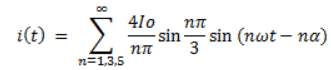
Find the value of 2nd harmonic source current amplitutue.- a)11.25 A
- b)0.256 A
- c)2.69 sin (ωt – 45) A
- d)0 A
Correct answer is option 'D'. Can you explain this answer?
A 3-phase full converter delivers a ripple free load current of 10 A with a firing angle delay of 45°. The input voltage is 3-phase, 400 V, 50 Hz. The source current is given by the following relation.
Find the value of 2nd harmonic source current amplitutue.
a)
11.25 A
b)
0.256 A
c)
2.69 sin (ωt – 45) A
d)
0 A
| | Gargi Basak answered |
2nd harmonics are absent in a 3-phase full converter, it has only odd number of harmonics i.e. 3rd, 5th etc.
What is the value of voltage at the output terminal when the freewheeling diode (FD) is conducting?
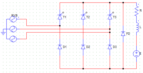
- a)Zero
- b)Maximum
- c)E
- d)It could be anything depending on α
Correct answer is option 'A'. Can you explain this answer?
What is the value of voltage at the output terminal when the freewheeling diode (FD) is conducting?
a)
Zero
b)
Maximum
c)
E
d)
It could be anything depending on α
| | Rounak Rane answered |
When FD is conducting it will short circuit the load terminal resulting in zero voltage. It won’t be E because the terminals are shorted. It can be E when none of the devices are conducting (This can happen only when α > 120°).
Chapter doubts & questions for Three Phase Line Commutated Converter - Power Electronics 2026 is part of Electrical Engineering (EE) exam preparation. The chapters have been prepared according to the Electrical Engineering (EE) exam syllabus. The Chapter doubts & questions, notes, tests & MCQs are made for Electrical Engineering (EE) 2026 Exam. Find important definitions, questions, notes, meanings, examples, exercises, MCQs and online tests here.
Chapter doubts & questions of Three Phase Line Commutated Converter - Power Electronics in English & Hindi are available as part of Electrical Engineering (EE) exam. Download more important topics, notes, lectures and mock test series for Electrical Engineering (EE) Exam by signing up for free.
Power Electronics5 videos|78 docs|46 tests |