


All Exams >
Electrical Engineering (EE) >
6 Months Preparation for GATE Electrical >
All Questions
All questions of Transmission Lines & Line Parameters for Electrical Engineering (EE) Exam
The most important cause of power loss in the transmission line is:- a)Resistance
- b)Capacitance
- c)Inductance
- d)Admittance
Correct answer is option 'A'. Can you explain this answer?
The most important cause of power loss in the transmission line is:
a)
Resistance
b)
Capacitance
c)
Inductance
d)
Admittance

|
Naroj Boda answered |
Series Resistance:
- The primary source of real power losses incurred in a transmission system is due to the resistance of the conductors.
- Power loss is directly proportional to the square of the RMS current traveling through the line.

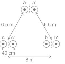
Determine inductance per phase per km in mH of a single circuit 450 kV line using a two-bundle conductor per phase as shown in the figure. (The radius of the conductor is 2.5cm)
Correct answer is between '0.80,0.90'. Can you explain this answer?
Determine inductance per phase per km in mH of a single circuit 450 kV line using a two-bundle conductor per phase as shown in the figure. (The radius of the conductor is 2.5cm)

|
Cstoppers Instructors answered |
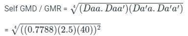
= 8.845 cm = 0.08845 m
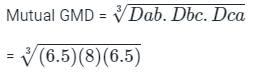
= 6.96 m
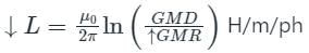
Inductance per phase = 2 × 10-7

= 8.732 × 10⁻⁷ H/m
= 0.8732 mH/km.
Bundled conductors are mainly used in high voltage overhead transmission lines to- a)Reduce line loss
- b)Reduce harmonics
- c)Reduce corona
- d)Increase strength
Correct answer is option 'C'. Can you explain this answer?
Bundled conductors are mainly used in high voltage overhead transmission lines to
a)
Reduce line loss
b)
Reduce harmonics
c)
Reduce corona
d)
Increase strength

|
Crack Gate answered |
Bundled conductor are those conductors which form from two or more stranded conductors, bundled together to get more current carrying capacity.
By using bundle conductors instead of the single conductor in the transmission line increases the GMR of the conductors.
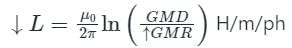
So, inductance reduces according to the following equation
Hence, the inductance per phase of the conductor decreases
So, capacitance increases according to the following equation
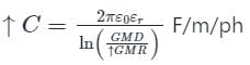
Hence, by using bundle conductors GMR is increased, so inductance L decrease and capacitance C increases.
Advantages of Bundled Conductors:
- Bundling of conductors leads to a reduction in line inductance.
- Bundling of conductors leads to increases in capacitance.
- An important advantage of bundled conductors is its ability to reduce corona discharge
- Reduction in the formation of corona discharge leads to less power loss and hence improved transmission efficiency of the line.
- Reduction in communication line interference.
Which of the following is not a valid advantage of bundle conductor?- a)Reduced reactance
- b)Reduced voltage gradient
- c)Reduced corona loss
- d)Increased reactance
Correct answer is option 'D'. Can you explain this answer?
Which of the following is not a valid advantage of bundle conductor?
a)
Reduced reactance
b)
Reduced voltage gradient
c)
Reduced corona loss
d)
Increased reactance
|
|
Crack Gate answered |
Bundled conductor are those conductors which form from two or more stranded conductors, bundled together to get more current carrying capacity.
By using bundle conductors instead of the single conductor in the transmission line increases the GMR of the conductors.
So, inductance reduces according to the following equation
Hence, the inductance per phase of the conductor decreases
So, capacitance increases according to the following equation
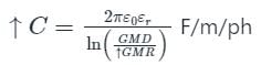
Hence, by using bundle conductors GMR is increased, so inductance L decreases and capacitance C increases.
Advantages of Bundled Conductors:
- Bundling of conductors leads to a reduction in line inductance.
- Bundling of conductors leads to increases in capacitance.
- An important advantage of bundled conductors is their ability to reduce corona discharge
- Reduction in the formation of corona discharge leads to less power loss and hence improved transmission efficiency of the line.
- Reduction in communication line interference.
Smooth reactor is connected between _____________- a)DC output of converter and load
- b)load and ground
- c)source and input of converter
- d)any of the mentioned
Correct answer is option 'A'. Can you explain this answer?
Smooth reactor is connected between _____________
a)
DC output of converter and load
b)
load and ground
c)
source and input of converter
d)
any of the mentioned
|
|
Zoya Sharma answered |
Smoothening reactor is connected between the dc output and load to provide sinusoidal source current.
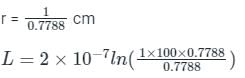
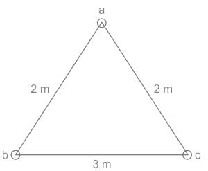
A three-phase line has its conductors at the corners of an equilateral triangle of side 1 m. The radius of each conductor is (1/0.7788) cm. The inductance per phase per km is given by:- a)0.921 mH/km
- b)0.4605 mH/km
- c)0.4605 mH/m
- d)0.921 mH/m
Correct answer is option 'A'. Can you explain this answer?
A three-phase line has its conductors at the corners of an equilateral triangle of side 1 m. The radius of each conductor is (1/0.7788) cm. The inductance per phase per km is given by:
a)
0.921 mH/km
b)
0.4605 mH/km
c)
0.4605 mH/m
d)
0.921 mH/m
|
|
Pooja Patel answered |
Concept:
The inductance of a three-phase line having its conductors at the corners of an equilateral triangle is given by:
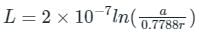
Calculation:
Given, a = 1m
L = 9.21 H/m
L = 9.21 × 10⁻¹ mH\km
L = 0.921 mH\km
The inductance of a three-phase line having its conductors at the corners of an equilateral triangle is given by:
Calculation:
Given, a = 1m
L = 9.21 H/m
L = 9.21 × 10⁻¹ mH\km
L = 0.921 mH\km
The spiraling of the conductors causes __________.- a)increase in resistance
- b)increase in frequency
- c)increase in voltage
- d)increase in current
Correct answer is option 'A'. Can you explain this answer?
The spiraling of the conductors causes __________.
a)
increase in resistance
b)
increase in frequency
c)
increase in voltage
d)
increase in current
|
|
Swati Shah answered |
Explanation:
Effect of Spiraling Conductors on Resistance:
- When conductors are spiraled, the length of the conductor increases due to the spiraling effect.
- The increase in length leads to an increase in the resistance of the conductor.
- This is because resistance is directly proportional to the length of the conductor.
Ohm's Law:
- According to Ohm's Law, resistance (R) is given by the formula R = V/I, where V is voltage and I is current.
- An increase in resistance will cause a decrease in current for a given voltage.
- This is because as resistance increases, the flow of current is impeded.
Impact on Voltage and Frequency:
- The spiraling of conductors primarily affects resistance and current, rather than voltage and frequency.
- Voltage is typically kept constant in a circuit, and the frequency is determined by the power supply and the components used.
- Therefore, the main impact of spiraling conductors is on the resistance and current in the circuit.
In conclusion, the spiraling of conductors causes an increase in resistance, which ultimately affects the flow of current in the circuit. This can have implications for the overall performance and efficiency of the electrical system.
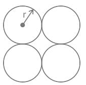
The geometric mean radius of a conductor, having four equal strands with each strand of radius ‘r’, as shown in the figure below, is
- a)4r
- b)1.414r
- c)2r
- d)1.723r
Correct answer is option 'D'. Can you explain this answer?
The geometric mean radius of a conductor, having four equal strands with each strand of radius ‘r’, as shown in the figure below, is
a)
4r
b)
1.414r
c)
2r
d)
1.723r
|
|
Zoya Sharma answered |
Concept:
GMR is defined as the effective distance over which self magnetic flux linkages occur
For a solid conductor with radius r,

GMR = r' = 0.7788r
GMR is less than the physical radius of the conductor.
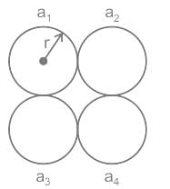
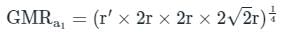
In the given figure, standard conductor with four identical strands touching each other is given with equal radius r.
= 1.722 r
Since each strands are identical.
∴ GMR of conductor will be equal to GMR of strand i.e.,
GMRcond = GMRa1
= 1.722 r
Therefore, correct option is (d)
GMR is defined as the effective distance over which self magnetic flux linkages occur
For a solid conductor with radius r,
GMR = r' = 0.7788r
GMR is less than the physical radius of the conductor.
In the given figure, standard conductor with four identical strands touching each other is given with equal radius r.
= 1.722 r
Since each strands are identical.
∴ GMR of conductor will be equal to GMR of strand i.e.,
GMRcond = GMRa1
= 1.722 r
Therefore, correct option is (d)
When subjected to short circuit, ______ conductor would experience maximum damage.- a)Copper
- b)Aluminium
- c)A.C.S.R
- d)Steel
Correct answer is option 'B'. Can you explain this answer?
When subjected to short circuit, ______ conductor would experience maximum damage.
a)
Copper
b)
Aluminium
c)
A.C.S.R
d)
Steel

|
Machine Experts answered |
- A short circuit is an electrical circuit that allows a current to travel along an unintended path with no or very low electrical impedance. This results in an excessive current flowing through the circuit.
- A short circuit fault can, within milliseconds, becomes a thousand times larger than the normal operating current of the system.
- Damage from the short circuits can be reduced or prevented by employing fuses, circuit breakers, or other overload protection, which disconnects the power in reaction to excessive current.
- Overload protection must be chosen according to the current rating of the circuit.
- During a short circuit, the current becomes large enough to produce excessive heat which can damage the conductor.
- Current (short circuit excessive current) being equal in all four conductors (Aluminum, copper, steel, ACSR) diverge the attention to the resistance of these conductors for the generation of heat during a short circuit.
- Aluminum has the highest resistance among them all, thus it would produce maximum heat during the short circuit. Also melting point of aluminum is least among them all, thus become of maximum heat generated, it could melt easily and can cause maximum damage when subjected to short circuits.
Note:
Heat generated = I2 Rt
Where I = Current (short circuit current)
R = Resistance of the conductor
t = time (in sec)
Consider the following types of transmission lines: - Open-wire line
- Twin-lead wire
- Coaxial cable
The capacitance per metre will be least in which of the above transmission lines?- a)1 only
- b)2 only
- c)3 only
- d)1, 2 and 3
Correct answer is option 'A'. Can you explain this answer?
Consider the following types of transmission lines:
- Open-wire line
- Twin-lead wire
- Coaxial cable
The capacitance per metre will be least in which of the above transmission lines?
a)
1 only
b)
2 only
c)
3 only
d)
1, 2 and 3
|
|
Pooja Patel answered |
Open-wire line:
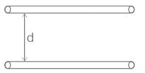
The capacitance of an open-wire line is given by,

Where r is the radius of the conductor
d is the distance between the lines
Twin-lead wire:
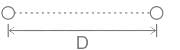
The capacitance of a twin-lead wire is given by,

Where r is the radius of the conductor
D is the distance between the conductors
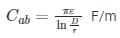
Coaxial cable:
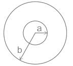
The capacitance of a co-axial cable is given by,

Where b is the radius of the outer conductor
a is the radius of the inner conductor
The capacitance of an open-wire line is given by,
Where r is the radius of the conductor
d is the distance between the lines
Twin-lead wire:
The capacitance of a twin-lead wire is given by,
Where r is the radius of the conductor
D is the distance between the conductors
Coaxial cable:
The capacitance of a co-axial cable is given by,
Where b is the radius of the outer conductor
a is the radius of the inner conductor
The surge impedance of multiple conductor lines as compared to single line is _______- a)higher
- b)lower
- c)same
- d)length dependent
Correct answer is option 'B'. Can you explain this answer?
The surge impedance of multiple conductor lines as compared to single line is _______
a)
higher
b)
lower
c)
same
d)
length dependent
|
|
Vibhor Goyal answered |
Due to the reduced GMD, the impedance decreases and so the surge impedance.
_______ material is used for the making of the ground wire in the transmission system.- a)Galvanised steel
- b)Steel
- c)Cast iron
- d)Aluminium
Correct answer is option 'A'. Can you explain this answer?
_______ material is used for the making of the ground wire in the transmission system.
a)
Galvanised steel
b)
Steel
c)
Cast iron
d)
Aluminium
|
|
Crack Gate answered |
Galvanised steel is used in the ground wire.
Self GMD method is used to evaluate- a)Inductance
- b)Capacitance
- c)Inductance and capacitance both of the over head transmission lines
- d)None of the above
Correct answer is option 'A'. Can you explain this answer?
Self GMD method is used to evaluate
a)
Inductance
b)
Capacitance
c)
Inductance and capacitance both of the over head transmission lines
d)
None of the above
|
|
Zoya Sharma answered |
Self GMD or GMR:
- Self GMD is also called GMR. GMR stands for Geometrical Mean Radius.
- GMR is calculated for each phase separately.
- self-GMD of a conductor depends upon the size and shape of the conductor
- GMR is independent of the spacing between the conductors.
GMD:
- GMD stands for Geometrical Mean Distance.
- It is the equivalent distance between conductors.
- GMD depends only upon the spacing
- GMD comes into the picture when there are two or more conductors per phase.
The inductance of the single-phase two-wire line is
GMD = Mutual Geometric Mean Distance = D
GMR = 0.7788r
r = Radius of the conductor
The capacitance between two conductors is
In the calculation of the capacitance, the inner radius of the conductor not considered
Therefore, The self GMD method is used to evaluate Inductance only.
GMD = Mutual Geometric Mean Distance = D
GMR = 0.7788r
r = Radius of the conductor
The capacitance between two conductors is
In the calculation of the capacitance, the inner radius of the conductor not considered
Therefore, The self GMD method is used to evaluate Inductance only.
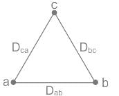
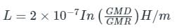
Consider an overhead transmission line with 3-phase, 50 Hz balanced system with conductors located at the vertices of an equilateral triangle of length Dab = Dbc = Dca = 1 m as shown in figure below. The resistances of the conductors are neglected. The geometric mean radius (GMR) of each conductor is 0.01 m. Neglecting the effect of ground, the magnitude of positive sequence reactance in Ω/km (rounded off to three decimal places) is _________
Correct answer is between '0.271,0.301'. Can you explain this answer?
Consider an overhead transmission line with 3-phase, 50 Hz balanced system with conductors located at the vertices of an equilateral triangle of length Dab = Dbc = Dca = 1 m as shown in figure below. The resistances of the conductors are neglected. The geometric mean radius (GMR) of each conductor is 0.01 m. Neglecting the effect of ground, the magnitude of positive sequence reactance in Ω/km (rounded off to three decimal places) is _________

|
Pioneer Academy answered |
Dab = Dbc = Dca = 1m
GMD = 1 m
GMR = 0.01 m
frequency (f) = 50 Hz
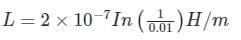
= 9.21 × 10⁻⁷ H/m
XL = 2πfL
= 2π × 50 × 9.21 × 10-7
= 0.2893 × 10⁻³ Ω/m
= 0.2893 Ω/km
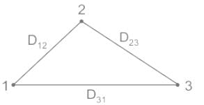
Calculate the equivalent mutual-GMD of the conductor arrangement.
Given: D12 = 2.5 m, D23 = 4.5 m, D31 = 2 m.
- a)3.54 m
- b)4.74 m
- c)2.82 m
- d)22.5 m
Correct answer is option 'C'. Can you explain this answer?
Calculate the equivalent mutual-GMD of the conductor arrangement.
Given: D12 = 2.5 m, D23 = 4.5 m, D31 = 2 m.
a)
3.54 m
b)
4.74 m
c)
2.82 m
d)
22.5 m
|
|
Naroj Boda answered |
Concept:
For a triangle configuration of conductors , the mutual-GMD is given by:
GMD = (D12 × D23 × D31)1/3
Calculation:
Given; D12 = 2.5 m, D23 = 4.5 m, D31 = 2 m
GMD = (2.5 × 4.5 × 2)1/3
GMD = 2.82 m
For a triangle configuration of conductors , the mutual-GMD is given by:
GMD = (D12 × D23 × D31)1/3
Calculation:
Given; D12 = 2.5 m, D23 = 4.5 m, D31 = 2 m
GMD = (2.5 × 4.5 × 2)1/3
GMD = 2.82 m
Ripple of the DC-output at power converter is ____________- a)maximum value of instantaneous difference between average and instantaneous value
- b)minimum value of instantaneous difference between average and instantaneous value
- c)average value of output
- d)maximum value of instantaneous value
Correct answer is option 'A'. Can you explain this answer?
Ripple of the DC-output at power converter is ____________
a)
maximum value of instantaneous difference between average and instantaneous value
b)
minimum value of instantaneous difference between average and instantaneous value
c)
average value of output
d)
maximum value of instantaneous value
|
|
Hrishikesh Yadav answered |
Understanding Ripple in DC-Output of Power Converters
Ripple in the DC output of a power converter refers to the small, unwanted fluctuations in the output voltage or current. It is essential to understand ripple because it can affect the performance of electronic devices powered by the converter.
Definition of Ripple
- Ripple is defined as the maximum value of the instantaneous difference between the average output voltage (or current) and the instantaneous voltage (or current) at any given moment.
Why Option A is Correct
- The correct answer, option 'A', states that ripple is the maximum value of the instantaneous difference between the average and instantaneous values. This is crucial because:
- Instantaneous vs. Average Value: The average value represents the steady-state output level, while the instantaneous value shows fluctuations. Ripple measures how much these instantaneous values deviate from the average.
- Importance of Maximum Value: Focusing on the maximum difference ensures that the worst-case scenario is accounted for, which is vital for assessing the impact on the connected load.
- Impact on Performance: High ripple can cause issues such as overheating, reduced efficiency, and interference in sensitive electronic circuits. Therefore, minimizing ripple is a key design consideration in power converters.
Other Options Explained
- Option B: Minimum value of instantaneous difference is incorrect because it does not capture the worst-case fluctuations.
- Option C: Average value of output does not account for ripple, which concerns variations around this average.
- Option D: Maximum value of instantaneous output does not reflect the discrepancy compared to the average output, thus missing the essence of ripple.
In summary, ripple is a critical parameter in power converters, and understanding it helps in designing more efficient and reliable electrical systems.
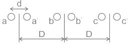
Refer to the following figure; the radius of each conductor is 0.03 m. It is also known that the spacing between phase conductors is 35 cm and the distance between the phases (D) is 4 m. Find the value of the average inductance of three-phase line arranged.
- a)1.2 mH/km
- b)22 mH/km
- c)0.34 mH/km
- d)12 mH/km
Correct answer is option 'C'. Can you explain this answer?
Refer to the following figure; the radius of each conductor is 0.03 m. It is also known that the spacing between phase conductors is 35 cm and the distance between the phases (D) is 4 m. Find the value of the average inductance of three-phase line arranged.
a)
1.2 mH/km
b)
22 mH/km
c)
0.34 mH/km
d)
12 mH/km
|
|
Pioneer Academy answered |
Calculation:
Self GMD or GMR:
Self GMD or GMR:
- Self GMD is also called GMR. GMR stands for Geometrical Mean Radius.
- GMR is calculated for each phase separately.
- self-GMD of a conductor depends upon the size and shape of the conductor
- GMR is independent of the spacing between the conductors.
GMD:
- GMD stands for Geometrical Mean Distance.
- It is the equivalent distance between conductors.
- GMD depends only upon the spacing
- GMD comes into the picture when there are two or more conductors per phase.
The inductance per phase is given as,
GMD = Mutual Geometric Mean Distance = D
GMR = 0.7788r
r = Radius of the conductor
Calculation:
Given conductor configuration,
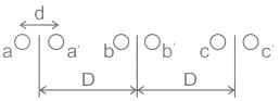
r = 0.03 m
d = 35 cm = 0.35 m
D = 4 m
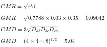
The inductance per phase is given as,
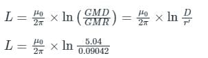
L = 0.8041 mH/km
Note: According to the Official UPRVUNL JE EE 2014 Previous Year Paper, then select option was 2.2 mH/km. Because of calculation, We correct the option accordingly
GMD = Mutual Geometric Mean Distance = D
GMR = 0.7788r
r = Radius of the conductor
Calculation:
Given conductor configuration,
r = 0.03 m
d = 35 cm = 0.35 m
D = 4 m
The inductance per phase is given as,
L = 0.8041 mH/km
Note: According to the Official UPRVUNL JE EE 2014 Previous Year Paper, then select option was 2.2 mH/km. Because of calculation, We correct the option accordingly
(i) Bipolar link has two conductors
(ii) Both conductors have same magnitude of voltage.- a)(i) is False & (ii) is True
- b)(i) is True & (ii) is True
- c)Both are false
- d)(i) is True & (ii) is False
Correct answer is option 'B'. Can you explain this answer?
(i) Bipolar link has two conductors
(ii) Both conductors have same magnitude of voltage.
(ii) Both conductors have same magnitude of voltage.
a)
(i) is False & (ii) is True
b)
(i) is True & (ii) is True
c)
Both are false
d)
(i) is True & (ii) is False
|
|
Sharmila Kulkarni answered |
Understanding Bipolar Links
Bipolar links are commonly used in electrical engineering to facilitate the transmission of signals. Let's break down the statements provided:
Statement Analysis
- (i) Bipolar link has two conductors.
- This statement is True.
- A bipolar link indeed consists of two conductors, often referred to as the positive and negative conductors. This setup allows for balanced transmission, reducing electromagnetic interference.
- (ii) Both conductors have the same magnitude of voltage.
- This statement is also True.
- In a bipolar system, the two conductors carry equal but opposite voltages. While the magnitude of the voltages is the same, their polarities differ. For example, if one conductor is at +5V, the other will be at -5V.
Conclusion
Given the analysis above, both statements are correct. Thus, the correct answer is:
Option B: (i) is True & (ii) is True
This understanding is crucial in various applications, including telecommunications and data transmission, where bipolar links optimize signal integrity and reduce noise.
The presence of earth in case of overhead transmission line- a)increases capacitance
- b)increases inductance
- c)decreases capacitance
- d)decreases inductance
Correct answer is option 'A'. Can you explain this answer?
The presence of earth in case of overhead transmission line
a)
increases capacitance
b)
increases inductance
c)
decreases capacitance
d)
decreases inductance
|
|
Nandita Bajaj answered |
Effect of Earth on Overhead Transmission Line
Capacitance of Overhead Transmission Line
- Capacitance is the ability of a conductor to store electric charge.
- The overhead transmission line consists of conductors in the air.
- The presence of the earth near the conductors increases the capacitance of the line.
- This is because the earth acts as a conductor and provides a path for the current to flow.
- The earth also acts as a dielectric material between the conductor and itself, which increases the capacitance.
Inductance of Overhead Transmission Line
- Inductance is the ability of a conductor to store energy in a magnetic field.
- The overhead transmission line consists of conductors in the air.
- The presence of the earth near the conductors decreases the inductance of the line.
- This is because the earth acts as a magnetic field and provides a path for the magnetic field to flow.
- The earth also acts as a magnetic material between the conductor and itself, which decreases the inductance.
Conclusion
- The presence of earth near the overhead transmission line affects both capacitance and inductance.
- The capacitance increases while the inductance decreases.
- This is due to the earth acting as both a conductor and a dielectric material for capacitance and as a magnetic field and magnetic material for inductance.
In a transmission line system, the feeders act as input to _________- a)distributors
- b)service mains
- c)transformer sub stations
- d)all of the mentioned
Correct answer is option 'A'. Can you explain this answer?
In a transmission line system, the feeders act as input to _________
a)
distributors
b)
service mains
c)
transformer sub stations
d)
all of the mentioned
|
|
Ashwin Kapoor answered |
Feeders in a Transmission Line System
Feeders in a transmission line system act as input to distributors. Here is an explanation of why feeders are connected to distributors:
Role of Feeders
- Feeders are the lines that carry power from the substations to different distribution points.
- They are responsible for transmitting electricity over long distances to meet the power demand of consumers.
Connection to Distributors
- Feeders are connected to distributors, which are responsible for further dividing and distributing the power to individual consumers.
- Distributors act as intermediaries between the main power source and end-users, ensuring that electricity is distributed efficiently and reliably.
Function of Distributors
- Distributors regulate the flow of electricity, manage voltage levels, and ensure that power is distributed evenly across different areas.
- They play a crucial role in maintaining a stable and reliable power supply to consumers.
Therefore, in a transmission line system, feeders serve as the input to distributors, enabling the efficient distribution of electricity from the substations to end-users.
Reactive power requirement of a power transmission system depends on __- a)Power angle δ
- b)|Vs|-|Vr|
- c)Vs
- d)Vr
Correct answer is option 'B'. Can you explain this answer?
Reactive power requirement of a power transmission system depends on __
a)
Power angle δ
b)
|Vs|-|Vr|
c)
Vs
d)
Vr
|
|
Ritika Mukherjee answered |
Understanding Reactive Power in Transmission Systems
Reactive power is a crucial aspect of power transmission systems, influencing stability and efficiency. It is primarily determined by the voltage magnitudes at both the sending and receiving ends of the transmission line.
Key Factors Influencing Reactive Power
- Voltage Magnitudes: The difference in voltage magnitudes between the sending end (Vs) and the receiving end (Vr) significantly impacts reactive power requirements. The relationship can be summarized as follows:
- Reactive power (Q) is affected by |Vs| - |Vr|, where |Vs| and |Vr| are the respective magnitudes of the sending and receiving voltages.
- Power Angle (δ): Although the power angle (δ) does play a role in the active power flow, it is not the primary determinant of reactive power. δ primarily affects the real power transfer rather than the reactive component.
- Voltage Levels: Higher voltage levels at the sending end can reduce the overall reactive power requirement, as they improve the ability to transmit power over long distances with less loss.
Conclusion
The correct answer being option 'B' emphasizes the significance of the voltage difference in determining reactive power requirements. In summary, reactive power is predominantly influenced by the magnitudes of the sending and receiving voltages, making |Vs| - |Vr| a critical factor in power transmission systems. Understanding this relationship is essential for engineers to ensure efficient and stable operation of electrical networks.
The overvoltage that occur mainly under converter stations are due to _________
(i) Lightening and switching overvoltage
(ii) Transients produced in conductors
(iii) Overvoltage due to fault clearing
Choose the correct option.- a)(i), (ii), (iii)
- b)(ii), (iii)
- c)(iii)
- d)(i), (ii)
Correct answer is option 'A'. Can you explain this answer?
The overvoltage that occur mainly under converter stations are due to _________
(i) Lightening and switching overvoltage
(ii) Transients produced in conductors
(iii) Overvoltage due to fault clearing
Choose the correct option.
(i) Lightening and switching overvoltage
(ii) Transients produced in conductors
(iii) Overvoltage due to fault clearing
Choose the correct option.
a)
(i), (ii), (iii)
b)
(ii), (iii)
c)
(iii)
d)
(i), (ii)
|
|
Pooja Patel answered |
All the statements are correct.
Before installing any transmission system, one has to decide about the type of the transmission system to be employed. Considering a monetary shortage and economical setup, one would take up _____________- a)underground system
- b)overhead system
- c)underground or overhead system
- d)can be chosen randomly
Correct answer is option 'B'. Can you explain this answer?
Before installing any transmission system, one has to decide about the type of the transmission system to be employed. Considering a monetary shortage and economical setup, one would take up _____________
a)
underground system
b)
overhead system
c)
underground or overhead system
d)
can be chosen randomly
|
|
Anushka Khanna answered |
Understanding Transmission Systems
When deciding on a transmission system, especially in the context of monetary constraints and the need for an economical setup, the choice often leans towards the overhead system. Here’s why:
Cost-Effectiveness
- Overhead systems are generally less expensive to install compared to underground systems.
- The materials required for overhead lines, such as poles and wires, are cheaper than the extensive infrastructure needed for underground cabling.
Maintenance and Repair
- Maintenance of overhead systems is simpler and less costly, as issues can be accessed easily from the ground.
- In contrast, underground systems may require significant excavation for repairs, leading to higher costs and longer downtimes.
Installation Time
- Overhead systems can be installed more quickly. This is crucial for projects with limited budgets and timelines.
- Underground systems involve complex processes, increasing both time and expenditure.
Environmental Considerations
- While underground systems are less visually obtrusive and are protected from weather conditions, the overhead systems are more adaptable to changes in environment and can be repositioned easily if required.
Conclusion
Given these factors, when faced with a monetary shortage and the need for an economical setup, the overhead transmission system emerges as the most viable option. It balances initial costs, maintenance, and installation efficiency, making it the preferred choice in many scenarios.
The function of steel wire in an ACSR conductor is to- a)compensate skin effect.
- b)take care of surges.
- c)provide additional mechanical strength.
- d)reduce inductanc
Correct answer is option 'C'. Can you explain this answer?
The function of steel wire in an ACSR conductor is to
a)
compensate skin effect.
b)
take care of surges.
c)
provide additional mechanical strength.
d)
reduce inductanc
|
|
Crack Gate answered |
Concept:
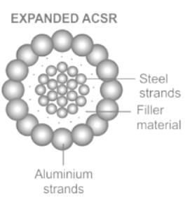
- Aluminium conductor steel-reinforced cable (ACSR) is a type of high-capacity, high-strength stranded conductor typically used in overhead power lines.
- The outer strands are high-purity aluminum, chosen for their good conductivity, low weight, and low cost.
- The center strand is galvanized steel for additional strength to help support the weight of the conductor and provide additional mechanical strength.
- Steel has higher strength than aluminum which allows for increased mechanical tension to be applied to the conductor.
- Steel also has lower elastic and inelastic deformation (permanent elongation) due to mechanical loading (e.g. wind and ice) as well as a lower coefficient of thermal expansion under current loading.
When the transmission line is lousy, then its characteristic impedance will not depend on which of the following?- a)Length
- b)Operating frequency
- c)Sub synchronous frequency
- d)Length and Sub synchronous frequency
Correct answer is option 'D'. Can you explain this answer?
When the transmission line is lousy, then its characteristic impedance will not depend on which of the following?
a)
Length
b)
Operating frequency
c)
Sub synchronous frequency
d)
Length and Sub synchronous frequency
|
|
Machine Experts answered |
For a lousy line, the characteristic impedance will be independent of its sub synchronous frequency and length.
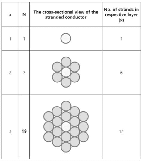
For 3 layers of ACSR conductor, number strands will be:- a)1
- b)7
- c)19
- d)37
Correct answer is option 'C'. Can you explain this answer?
For 3 layers of ACSR conductor, number strands will be:
a)
1
b)
7
c)
19
d)
37

|
Bayshore Academy answered |
Generally, the total number of strands in any conductor is given by the formulae
N = 3x2 – 3x + 1
Where x = no. of layers
If the currents in the two conductors of bipolar HDVC link is same, then _______- a)ground current is zero
- b)two poles work independently
- c)ground current zero and two poles work independently
- d)none of the mentioned
Correct answer is option 'B'. Can you explain this answer?
If the currents in the two conductors of bipolar HDVC link is same, then _______
a)
ground current is zero
b)
two poles work independently
c)
ground current zero and two poles work independently
d)
none of the mentioned
|
|
Raghav Nambiar answered |
Understanding Bipolar HVDC Links
Bipolar High Voltage Direct Current (HVDC) systems consist of two conductors that can transmit power in opposite directions. When analyzing the behavior of currents in these systems, it's important to consider the implications of equal current flow in both conductors.
Equal Currents in Conductors
- When the currents in both conductors are the same, it indicates that the system is balanced.
- This balance helps in maintaining system stability and prevents excessive voltage fluctuations.
Ground Current Consideration
- In a perfectly balanced bipolar HVDC system, the ground current should ideally be zero.
- However, if the currents are equal and opposite, any ground current typically produced due to imbalances is also nullified.
Independent Operation of Poles
- Each pole in a bipolar HVDC scheme operates independently regarding control and power flow.
- When currents are equal, any operational decision or failure in one pole does not directly affect the other pole's performance.
Conclusion
- Therefore, the correct option is that when the currents in the two conductors of a bipolar HVDC link are the same, the two poles can work independently.
- This independence is crucial for reliability and flexibility in power transmission.
In summary, while the ground current may be minimized in this scenario, the key takeaway is that the two poles can function without influencing one another, thereby enhancing the overall system's operational efficiency.
The ACSR (Aluminium Conductor Steel Reinforced) provides ______ sag and ______ Span than copper conductors.- a)lower, longer
- b)greater, longer
- c)lower, shorter
- d)greater, shorter
Correct answer is option 'A'. Can you explain this answer?
The ACSR (Aluminium Conductor Steel Reinforced) provides ______ sag and ______ Span than copper conductors.
a)
lower, longer
b)
greater, longer
c)
lower, shorter
d)
greater, shorter
|
|
Machine Experts answered |
Aluminum conductor steel reinforced(ACSR):
- It is one of the stranded conductors composed of one or more layers of hard-drawn 1350-H19 aluminum wire that is on galvanized coated steel core.
- The ACSR conductors are mainly used in distribution and transmission lines due to their high tensile strength, economical design, less weight, suitable for medium and long periods with fewer supports, and good properties of sag and high voltage overhead lines.
Advantages of ACSR conductors over copper conductors:
- The conductivity of the ACSR is higher than the copper conductor.
- ACSR conductor can be used for medium and long spans and needs less support.
- The mechanical performance and Tensile strength of the ACSR conductor are High.
- It provides lesser Sag than copper conductors.
In the figure shown below, a conductor consists of seven identical strands each having a radius of r.
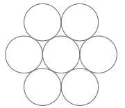
Determine the factor by which 'r' should be multiplied to find the self GMD of the conductor.
Correct answer is between '2.15,2.20'. Can you explain this answer?
In the figure shown below, a conductor consists of seven identical strands each having a radius of r.
Determine the factor by which 'r' should be multiplied to find the self GMD of the conductor.
Determine the factor by which 'r' should be multiplied to find the self GMD of the conductor.
|
|
Cstoppers Instructors answered |
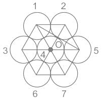

From configuration:
(GMR)1 = (GMR)2 = (GMR)3 = (GMR)5 = (GMR)6 = (GMR)7
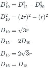
(GMR)4 =(D44 × D41 × D42 × D43 × D45 × D46 × D47)1/7
(GMR)4 = (.7788r × 2r × 2r × 2r × 2r × 2r × 2r)1/7
(GMR)4 = 1.747r
(GMR)1 = (D11 × D12 × D13 × D14 × D17 × D15 × D16)1/7
(GMR)1 =(.7788r × 2r × 2r × 2r × 4r × 2√3r × 2√3r)1/7
(GMR)1 = 2.257r
GMR=(1.747r × (2.257r)6)1/7
GMR = 2.175r
(GMR)1 = 2.257r
GMR=(1.747r × (2.257r)6)1/7
GMR = 2.175r
If the height of transmission tower is increased:- a)the line capacitance and inductance will not change
- b)the line capacitance will decrease and line inductance will increase
- c)the line capacitance will decrease but line inductance will remain unchanged
- d)the line capacitance will increase but line inductance will decrease
Correct answer is option 'C'. Can you explain this answer?
If the height of transmission tower is increased:
a)
the line capacitance and inductance will not change
b)
the line capacitance will decrease and line inductance will increase
c)
the line capacitance will decrease but line inductance will remain unchanged
d)
the line capacitance will increase but line inductance will decrease
|
|
Charvi Reddy answered |
Explanation:
When the height of a transmission tower is increased, it affects the line capacitance and inductance. The line capacitance is the ability of the line to store electric charge, while the line inductance is the ability of the line to store magnetic energy. The relationship between the height of the transmission tower and the line capacitance and inductance is explained as follows:
Effect on line capacitance:
- The capacitance of a transmission line is directly proportional to the spacing between the conductors and inversely proportional to the height of the tower.
- When the height of the tower is increased, the spacing between the conductors remains the same, but the distance between the conductors and the ground increases.
- As a result, the capacitance of the line decreases because the electric field between the conductors and the ground weakens.
Effect on line inductance:
- The inductance of a transmission line is directly proportional to the height of the tower and inversely proportional to the spacing between the conductors.
- When the height of the tower is increased, the distance between the conductors and the ground increases, but the spacing between the conductors remains the same.
- As a result, the inductance of the line remains unchanged.
Conclusion:
Based on the above explanation, we can conclude that when the height of the transmission tower is increased:
- The line capacitance will decrease because the distance between the conductors and the ground increases.
- The line inductance will remain unchanged because the spacing between the conductors remains the same. Therefore, option 'C' is the correct answer.
If the separation between the three phases of a transmission line is increased then- a)The inductance will increase and capacitance will remain unchanged
- b)Both the inductance and capacitance will increase
- c)The inductance will increase and the capacitance will decrease
- d)The inductance will decrease and the capacitance will increase
Correct answer is option 'C'. Can you explain this answer?
If the separation between the three phases of a transmission line is increased then
a)
The inductance will increase and capacitance will remain unchanged
b)
Both the inductance and capacitance will increase
c)
The inductance will increase and the capacitance will decrease
d)
The inductance will decrease and the capacitance will increase
|
|
Avik Saha answered |
Increasing the separation between the three phases of a transmission line has an impact on the inductance and capacitance of the line. The correct answer, option 'C', states that the inductance will increase and the capacitance will decrease. Let's understand why this is the case.
Inductance:
When the separation between the phases is increased, the distance between the conductors also increases. This results in an increase in the mutual inductance between the conductors. Mutual inductance is the phenomenon where the magnetic field generated by one conductor induces a voltage in the adjacent conductors. As the distance between the conductors increases, the magnetic field will have a larger area to couple with, leading to an increase in the mutual inductance.
Capacitance:
On the other hand, when the separation between the phases is increased, the distance between the conductors also increases. This results in a decrease in the capacitance between the conductors. Capacitance is the ability of a system of conductors to store electrical energy in an electric field. When the distance between the conductors increases, the electric field between them weakens, reducing the capacitance.
Overall effect:
So, when the separation between the three phases of a transmission line is increased, the inductance will increase due to the larger area for magnetic field coupling. At the same time, the capacitance will decrease due to the weakening electric field between the conductors. Therefore, the correct answer is option 'C' - the inductance will increase and the capacitance will decrease.
It's important to note that the inductance and capacitance of a transmission line have a significant impact on its performance. The inductance affects the line impedance, while the capacitance affects the line charging current and voltage levels. Understanding these characteristics is crucial for the design and operation of efficient and reliable transmission systems.
In emergency cases, another wire is installed in the system, that is widely known as ________________- a)Guy wire
- b)Earth wire
- c)Line wire
- d)Neutral wire
Correct answer is option 'A'. Can you explain this answer?
In emergency cases, another wire is installed in the system, that is widely known as ________________
a)
Guy wire
b)
Earth wire
c)
Line wire
d)
Neutral wire
|
|
Harshad Singh answered |
Understanding Guy Wires
In electrical systems, particularly those involving overhead lines, guy wires play a crucial role in ensuring stability and safety. Here’s a detailed breakdown of what guy wires are and their importance:
What are Guy Wires?
- Definition: Guy wires are tensioned cables used to support structures such as poles, towers, and antennas.
- Purpose: They are designed to stabilize these structures against wind forces and other environmental stresses.
Role in Emergency Situations
- Support: In emergency situations, additional guy wires may be installed to provide extra support to weakened structures.
- Preventing Collapse: By anchoring the structure more securely, guy wires help prevent collapse, which is crucial for maintaining power supply and ensuring safety.
Key Features of Guy Wires
- Material: Typically made from strong materials such as steel to withstand high tension and environmental forces.
- Installation: Proper installation involves calculating the right angles and tension to effectively stabilize the structure.
Comparison with Other Wires
- Earth Wire: Primarily used for grounding and safety, not for structural support.
- Line Wire: Carries electrical current but does not provide structural stability.
- Neutral Wire: Completes electrical circuits and maintains balance but lacks the tension support function of guy wires.
In summary, guy wires are essential for maintaining the integrity of electrical structures, especially in emergency scenarios where additional support is necessary. Their role in stabilizing systems cannot be overstated, making them a vital component in electrical engineering.
One would design the feeders of the transmission system based on its ____________- a)current capacity
- b)voltage drop
- c)operating voltage
- d)all of the mentioned
Correct answer is option 'A'. Can you explain this answer?
One would design the feeders of the transmission system based on its ____________
a)
current capacity
b)
voltage drop
c)
operating voltage
d)
all of the mentioned
|
|
Machine Experts answered |
Feeders do not have tappings and they are designed on the basis of current flowing through them.
The underground transmission and distribution of power is better than the corresponding overhead transmission and distribution in respect of _________- a)appearance and safety
- b)maintenance cost
- c)frequency of faults
- d)appearance, safety, maintenance, frequency
Correct answer is option 'D'. Can you explain this answer?
The underground transmission and distribution of power is better than the corresponding overhead transmission and distribution in respect of _________
a)
appearance and safety
b)
maintenance cost
c)
frequency of faults
d)
appearance, safety, maintenance, frequency

|
Engineers Adda answered |
All the points are advantageous with respect to overhead transmission line in an underground power transmission system.
The conductors of a three – phase 50 Hz, 125 km long transmission line are shown in the figure. The diameter of each conductor is 0.6 cm. What is the value of inductance per phase?
- a)0.1725 H
- b)1.825 H
- c)0.8625 H
- d)1.225 H
Correct answer is option 'A'. Can you explain this answer?
The conductors of a three – phase 50 Hz, 125 km long transmission line are shown in the figure. The diameter of each conductor is 0.6 cm. What is the value of inductance per phase?
a)
0.1725 H
b)
1.825 H
c)
0.8625 H
d)
1.225 H
|
|
Zoya Sharma answered |
Ds = 0.7788r = 0.7788 × 0.3 = 0.233 cm
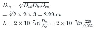
= 1.38 × 10⁻⁶ H/m
= 1.38 × 10⁻³ H/km
The value of the inductance
L = 1.38 × 10-3 × 125 = 0.1725 H
= 1.38 × 10⁻⁶ H/m
= 1.38 × 10⁻³ H/km
The value of the inductance
L = 1.38 × 10-3 × 125 = 0.1725 H
In cadmium copper conductors, addition of 1% to 2% cadmium to copper increases the tensile strength by approximately __________.- a)25%
- b)95%
- c)50%
- d)75%
Correct answer is option 'C'. Can you explain this answer?
In cadmium copper conductors, addition of 1% to 2% cadmium to copper increases the tensile strength by approximately __________.
a)
25%
b)
95%
c)
50%
d)
75%
|
|
Crack Gate answered |
Conductor Material (Cadmium copper):
- Copper was the preferred material for overhead conductors in earlier days, but, aluminum has replaced copper because of the much lower cost and lighter weight of the aluminum conductor compared with a copper conductor of the same resistance.
- But due to the low weight of aluminum, when it is used as overhead conductors for a long span, a considerable amount of sag is produced.
- So, cadmium copper conductors are preferred conductors for long distances.
- Cadmium-copper alloys contain approximately 98 to 99% of copper and up to 1.5% of cadmium.
- The addition of about 1% of cadmium to copper increases the tensile strength by up to 50%.
- Therefore, cadmium-copper conductors can be useful for exceptionally long spans.
If the transmission line is lossless, then its characteristic will be _________- a)√(L/C)
- b)√LC
- c)√(L+C)
- d)√(C/L)
Correct answer is option 'A'. Can you explain this answer?
If the transmission line is lossless, then its characteristic will be _________
a)
√(L/C)
b)
√LC
c)
√(L+C)
d)
√(C/L)
|
|
Harshad Singh answered |
Understanding Characteristic Impedance
In transmission lines, the characteristic impedance (Z0) plays a vital role in determining how signals propagate along the line. For a lossless transmission line, it is defined as:
Formula for Characteristic Impedance
- The characteristic impedance (Z0) of a lossless transmission line is given by the formula:
- Z0 = √(L/C)
Where:
- L = Inductance per unit length (H/m)
- C = Capacitance per unit length (F/m)
Why Lossless Matters
- A lossless transmission line implies that there are no resistive losses (R = 0) and no dielectric losses (G = 0).
- This condition ensures that the energy is conserved and that the impedance remains purely reactive.
Analysis of Options
- Option A: √(L/C) - This is correct as it directly represents the characteristic impedance of a lossless transmission line.
- Option B: √(LC) - This does not represent characteristic impedance and is incorrect.
- Option C: √(L+C) - This is also incorrect as it does not relate to the properties of transmission lines.
- Option D: √(C/L) - This is not a standard representation of characteristic impedance and is incorrect.
Conclusion
In summary, the characteristic impedance of a lossless transmission line is determined by the square root of the inductance per unit length divided by the capacitance per unit length, confirming that option A (√(L/C)) is the correct answer. Understanding this concept is crucial for efficient signal transmission in electrical engineering applications.
When ______ then the transmission line will act as a distortion less line.- a)RC = GL
- b)RG = LC
- c)R = G
- d)Cannot be determined
Correct answer is option 'A'. Can you explain this answer?
When ______ then the transmission line will act as a distortion less line.
a)
RC = GL
b)
RG = LC
c)
R = G
d)
Cannot be determined
|
|
Hridoy Chakraborty answered |
Understanding Distortionless Transmission Lines
To achieve a distortionless transmission line, certain conditions must be fulfilled regarding the parameters of the line. The relationship between resistance (R), conductance (G), inductance (L), and capacitance (C) plays a crucial role.
Condition for Distortionless Line
- The transmission line is defined as distortionless when the following condition is met:
- RC = GL
This equation indicates a balance between the reactive and resistive components of the line, ensuring that signal distortion due to the frequency response is minimized.
Explanation of Parameters
- R (Resistance): Represents the opposition to current flow within the line.
- G (Conductance): Indicates how easily the line can conduct current due to leakage.
- L (Inductance): The property that opposes the change in current.
- C (Capacitance): The ability of the line to store electrical energy in an electric field.
When RC = GL holds true:
- The wave velocity remains constant regardless of frequency.
- The attenuation of the signal does not vary with frequency, ensuring that all frequency components of a signal travel at the same speed.
Consequences of Distortion
- If the condition is not met, distortion occurs, leading to different frequencies within a signal experiencing different propagation speeds, thereby causing signal degradation.
In summary, for a transmission line to function as a distortionless medium, it must satisfy the condition RC = GL, effectively maintaining signal integrity across various frequencies.
(I) Unsymmetrical spacing configurations cause the line interference.
(II) Unsymmetrical spacing causes the voltage induction in the communication lines.
The above problems can be eliminated by ________ - a)transposition
- b)three phase
- c)parallel lines
- d)All of the above
Correct answer is option 'A'. Can you explain this answer?
(I) Unsymmetrical spacing configurations cause the line interference.
(II) Unsymmetrical spacing causes the voltage induction in the communication lines.
The above problems can be eliminated by ________
(II) Unsymmetrical spacing causes the voltage induction in the communication lines.
The above problems can be eliminated by ________
a)
transposition
b)
three phase
c)
parallel lines
d)
All of the above
|
|
Zoya Sharma answered |
Effect of Unsymmetrical Spacing of 3ϕ Line Conductors:
- Due to unsymmetrical spacing, flux linkage with all three phases is different. Because of this, there will be an unequal voltage drop in all three phases. Thus the voltage at the receiving end will not be the same for the three phases.
- Due to unsymmetrical spacing, the magnetic field external to the conductor is not zero. Thereby causing the induced voltage in adjacent electric circuits, thus producing the interference in communication lines.
- Unsymmetrical spacing configurations cause line interference.
The above-mentioned problems can be eliminated by the transposition of the 3ϕ line.
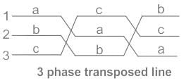
Transposition is the periodic swapping of positions of the conductors of a transmission line, in order to reduce interference and voltage induction in the 3ϕ transmission line.
Transposition is the periodic swapping of positions of the conductors of a transmission line, in order to reduce interference and voltage induction in the 3ϕ transmission line.
If ACSR conductor has specification as 48/7, which of the following statement is correct for the conductor?- a)The conductor has 48 strands
- b)The conductor has 55 strands
- c)The conductor has 48 aluminium and 7 steel strands
- d)The conductor has 48 steel and 7 aluminium strands
Correct answer is option 'C'. Can you explain this answer?
If ACSR conductor has specification as 48/7, which of the following statement is correct for the conductor?
a)
The conductor has 48 strands
b)
The conductor has 55 strands
c)
The conductor has 48 aluminium and 7 steel strands
d)
The conductor has 48 steel and 7 aluminium strands
|
|
Machine Experts answered |
Representation of ACSR Conductor:
A standard conductor is represented as A/S/D for ACSR conductor.
Where,
A is the number of aluminum strands.
S is the number of steel strands.
D is the diameter of each strand.
Example: If the ACSR conductor having 7 steel strands surrounded by 25 aluminum conductors will be specified as 25/7.
Solution:
ACSR conductor has specification as 48/7
The conductor has 48 aluminium and 7 steel strands
Which of the following situations is very useless when the series capacitors to the transmission line are of little use?- a)When the VAR requirement is small
- b)When the VAR requirement is large
- c)When the VAR requirement is varying
- d)Cannot be determined
Correct answer is option 'A'. Can you explain this answer?
Which of the following situations is very useless when the series capacitors to the transmission line are of little use?
a)
When the VAR requirement is small
b)
When the VAR requirement is large
c)
When the VAR requirement is varying
d)
Cannot be determined
|
|
Vibhor Goyal answered |
Because capacitance is usually neglected for a small transmission line.
The volume of copper required in a transmission system is proportional to _________- a)voltage and power factor
- b)power factor
- c)voltage
- d)current
Correct answer is option 'A'. Can you explain this answer?
The volume of copper required in a transmission system is proportional to _________
a)
voltage and power factor
b)
power factor
c)
voltage
d)
current
|
|
Machine Experts answered |
Weight of the copper is proportional to voltage and power factor.
In India, the preferred poles used in the transmission and distribution is ______- a)Steel poles
- b)RCC poles
- c)Steel and RCC poles
- d)Wood poles
Correct answer is option 'C'. Can you explain this answer?
In India, the preferred poles used in the transmission and distribution is ______
a)
Steel poles
b)
RCC poles
c)
Steel and RCC poles
d)
Wood poles
|
|
Crack Gate answered |
The most commonly used poles are steel and RCC poles.
A single-phase transmission line has two conductors each of 10mm radius. These are fixed at a center-to-center distance of 1m in a horizontal plane. This is now converted to a three-phase transmission line by introducing a third conductor of the same radius. This conductor is fixed at an equal distance D from the two single-phase conductors. The three-phase line is fully transposed. The positive sequence inductance per phase of the three-phase system is to be 5% more than that of the inductance per conductor of the single-phase system. The distance D, in meters, is _______.
Correct answer is between '1.41,1.47'. Can you explain this answer?
A single-phase transmission line has two conductors each of 10mm radius. These are fixed at a center-to-center distance of 1m in a horizontal plane. This is now converted to a three-phase transmission line by introducing a third conductor of the same radius. This conductor is fixed at an equal distance D from the two single-phase conductors. The three-phase line is fully transposed. The positive sequence inductance per phase of the three-phase system is to be 5% more than that of the inductance per conductor of the single-phase system. The distance D, in meters, is _______.
|
|
Bhavana Reddy answered |
To find the distance D in meters for the three-phase transmission line, we need to analyze the given information and apply the relevant formulas. Let's break it down step by step.
1. Single-phase transmission line:
- Two conductors with a radius of 10mm are fixed at a center-to-center distance of 1m in a horizontal plane.
- The inductance per conductor of the single-phase system is denoted as Ls.
2. Three-phase transmission line:
- A third conductor with the same radius of 10mm is introduced.
- The three-phase line is fully transposed, meaning the positions of the conductors are periodically exchanged to balance the system.
- The positive sequence inductance per phase of the three-phase system is 5% more than that of the inductance per conductor of the single-phase system.
To find the distance D, we can use the formula for the inductance of a transmission line:
L = (μ/2π) * ln(D/r)
where L is the inductance, μ is the permeability of the medium (typically air or vacuum), D is the distance between the conductors, and r is the radius of the conductors.
Let's denote the positive sequence inductance per phase of the three-phase system as Lt. Given that it is 5% more than the inductance per conductor of the single-phase system (Ls), we can write:
Lt = Ls + 0.05Ls
Lt = 1.05Ls
To find D, we can equate the inductance formulas for the single-phase and three-phase systems:
(μ/2π) * ln(D/r) = Lt
(μ/2π) * ln(D/r) = 1.05Ls
Now, we can solve for D by substituting the values:
- μ is a constant for air or vacuum.
- r is the radius of the conductors (10mm or 0.01m).
- Lt = 1.05Ls
Solving the equation will give us the value of D, which falls within the range of 1.41 to 1.47 meters as stated in the correct answer.
A.C.S.R conductor having 7 steel strands surrounded by 25 aluminium conductors will be specified as- a)25/7
- b)7/25
- c)50/15
- d)15/50
Correct answer is option 'A'. Can you explain this answer?
A.C.S.R conductor having 7 steel strands surrounded by 25 aluminium conductors will be specified as
a)
25/7
b)
7/25
c)
50/15
d)
15/50
|
|
Bijoy Mehta answered |
Explanation:
In the given question, we have an ACSR (Aluminium Conductor Steel Reinforced) conductor with 7 steel strands surrounded by 25 aluminium conductors. We need to specify this configuration.
ACSR Conductor:
ACSR conductor is a type of overhead conductor that consists of a central core made of steel strands surrounded by one or more layers of aluminium conductors. It is widely used in transmission and distribution lines due to its high strength and conductivity.
Configuration of ACSR Conductor:
The configuration of the ACSR conductor is specified by indicating the number of steel strands and the number of aluminium conductors. In this case, we have 7 steel strands and 25 aluminium conductors.
Specification:
To specify the ACSR conductor configuration, we represent it as a fraction, with the number of aluminium conductors in the numerator and the number of steel strands in the denominator.
Calculation:
In this case, the specification of the ACSR conductor with 7 steel strands and 25 aluminium conductors will be 25/7.
Answer:
Therefore, the correct answer is option 'A' which represents the ACSR conductor configuration as 25/7.
(i) Monopolar DC link has one energised conductor of positive polarity.
(ii) It was ground as return path
Opt the most appropriate.- a)(i) is False & (ii) is True
- b)(i) is True & (ii) is True
- c)Both are false
- d)(i) is True & (ii) is False
Correct answer is option 'A'. Can you explain this answer?
(i) Monopolar DC link has one energised conductor of positive polarity.
(ii) It was ground as return path
Opt the most appropriate.
(ii) It was ground as return path
Opt the most appropriate.
a)
(i) is False & (ii) is True
b)
(i) is True & (ii) is True
c)
Both are false
d)
(i) is True & (ii) is False
|
|
Nitin Chawla answered |
Explanation:
Monopolar DC Link:
- In a monopolar DC link, there is only one energized conductor with positive polarity. This means that only one conductor carries the current in the system.
Ground as Return Path:
- In a monopolar DC link system, the ground is used as the return path for the current. The current flows through the energized conductor and returns through the ground.
Explanation of Option (a):
- The statement (i) is true because a monopolar DC link does have one energized conductor of positive polarity.
- The statement (ii) is also true because in a monopolar DC link, the ground is used as the return path for the current.
- Therefore, the most appropriate option is (a) where (i) is true and (ii) is true.
This explanation clarifies why option 'A' is the correct answer for this question.
Match the following for ABCD parameters.
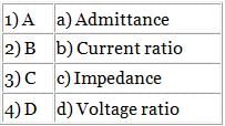
- a)1-a, 2-b, 3-d, 4- c
- b)1-d, 2-c, 3-a, 4-b
- c)1-b, 2-a, 3-c, 4-d
- d)1-c, 2-d, 3-b, 4-a
Correct answer is option 'B'. Can you explain this answer?
Match the following for ABCD parameters.
a)
1-a, 2-b, 3-d, 4- c
b)
1-d, 2-c, 3-a, 4-b
c)
1-b, 2-a, 3-c, 4-d
d)
1-c, 2-d, 3-b, 4-a
|
|
Naroj Boda answered |
Concept:
The ABCD parameters are given by:
V1 = AV2 - BI2
I1 = CV2 - DI2
where, V1 and I1 are the input voltage and current
V2 and I2 are the output voltage and current
Case 1: When output current (I2) = 0
A = V1/V2 = Voltage ratio
C = I1/V2 = Admittanc
Case 2: When output voltage (V2) = 0
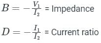
Hence, option 2 is correct.
The ABCD parameters are given by:
V1 = AV2 - BI2
I1 = CV2 - DI2
where, V1 and I1 are the input voltage and current
V2 and I2 are the output voltage and current
Case 1: When output current (I2) = 0
A = V1/V2 = Voltage ratio
C = I1/V2 = Admittanc
Case 2: When output voltage (V2) = 0
Hence, option 2 is correct.
A single-phase line consists of two long solid conductors, each having a radius of r metre separated by a distance of D metre. What will be capacitance between the conductor?- a)
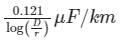
- b)
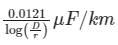
- c)

- d)
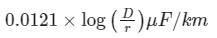
Correct answer is option 'B'. Can you explain this answer?
A single-phase line consists of two long solid conductors, each having a radius of r metre separated by a distance of D metre. What will be capacitance between the conductor?
a)
b)
c)
d)
|
|
Pioneer Academy answered |
Concept:
The capacitance between the conductors of a 1-ϕ, 2- long solid conductors transmission line:
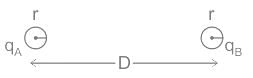
D = distance of separation between two long solid conductors
r = radius of each long solid conductor
qA, q, = Charge across A and B conductors
The standard result for the capacitance between the conductors
CAB = qA / VAB
= qB / VBA
= π ϵr ϵ∘ / ln(D / r) .....(i
Calculations:
ϵ∘ = 8.85 × 10⁻¹²
ϵr = 1 (for air)
π = 3.14
ln (D / r) = 2.303 log (D / r)
From equation (i)
CAB = (3.14 × 8.85 × 10-12 × 1) / (2.303 log (D / r)) F/m
The capacitance between the conductors of a 1-ϕ, 2- long solid conductors transmission line:
D = distance of separation between two long solid conductors
r = radius of each long solid conductor
qA, q, = Charge across A and B conductors
The standard result for the capacitance between the conductors
CAB = qA / VAB
= qB / VBA
= π ϵr ϵ∘ / ln(D / r) .....(i
Calculations:
ϵ∘ = 8.85 × 10⁻¹²
ϵr = 1 (for air)
π = 3.14
ln (D / r) = 2.303 log (D / r)
From equation (i)
CAB = (3.14 × 8.85 × 10-12 × 1) / (2.303 log (D / r)) F/m
Chapter doubts & questions for Transmission Lines & Line Parameters - 6 Months Preparation for GATE Electrical 2025 is part of Electrical Engineering (EE) exam preparation. The chapters have been prepared according to the Electrical Engineering (EE) exam syllabus. The Chapter doubts & questions, notes, tests & MCQs are made for Electrical Engineering (EE) 2025 Exam. Find important definitions, questions, notes, meanings, examples, exercises, MCQs and online tests here.
Chapter doubts & questions of Transmission Lines & Line Parameters - 6 Months Preparation for GATE Electrical in English & Hindi are available as part of Electrical Engineering (EE) exam.
Download more important topics, notes, lectures and mock test series for Electrical Engineering (EE) Exam by signing up for free.
6 Months Preparation for GATE Electrical
675 videos|1297 docs|786 tests
|
|
© EduRev
|
Education Revolution
|


|


Signup on EduRev and stay on top of your study goals
10M+ students crushing their study goals daily