


All Exams >
Mechanical Engineering >
6 Months Preparation for GATE Mechanical >
All Questions
All questions of Stress and Strain for Mechanical Engineering Exam
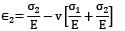
An elastic material of Young’s modulus E and Poisson’s ratio v is subjected to a compressive stress of σ1 in the longitudinal direction.Suitable lateral compressive stress σ2 is also applied along the other two lateral directions to limit the net strain in each of the lateral directions to half of the magnitude that would be under σ1 acting alone. The magnitude of σ2 is- a)

- b)

- c)

- d)

Correct answer is option 'B'. Can you explain this answer?
An elastic material of Young’s modulus E and Poisson’s ratio v is subjected to a compressive stress of σ1 in the longitudinal direction.
Suitable lateral compressive stress σ2 is also applied along the other two lateral directions to limit the net strain in each of the lateral directions to half of the magnitude that would be under σ1 acting alone. The magnitude of σ2 is
a)
b)
c)
d)

|
Naroj Boda answered |
Σ1 is acting along longitudinal direction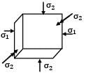

Strain in lateral direction
Strain in lateral direction when σ1 acts alone.

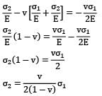
A bar of length L tapers uniformly from diameter 1.1 D at one end to 0.9 D at the other end. The elongation due to axial pull is computed using mean diameter D. What is the approximate error in computed elongation?- a) 10%
- b) 5%
- c) 1%
- d) 0.5%
Correct answer is option 'C'. Can you explain this answer?
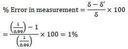
A bar of length L tapers uniformly from diameter 1.1 D at one end to 0.9 D at the other end. The elongation due to axial pull is computed using mean diameter D. What is the approximate error in computed elongation?
a)
10%
b)
5%
c)
1%
d)
0.5%
|
|
Zoya Sharma answered |
Actual elongation,
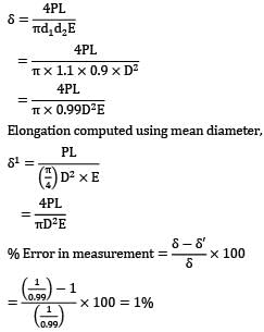
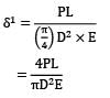
Elongation computed using mean diameter,
If the rigid rod fitted snugly between the supports as shown in the figure below, is heated, the stress induced in it due to 20℃ rise in temperature will be (α = 12.5 x 10⁻⁶/℃ E = 200GPa)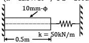
- a) 0.07945 MPa
- b) −0.07945 MPa
- c) −0.03972 MPa
- d) 0.03972 MPa
Correct answer is option 'B'. Can you explain this answer?
If the rigid rod fitted snugly between the supports as shown in the figure below, is heated, the stress induced in it due to 20℃ rise in temperature will be (α = 12.5 x 10⁻⁶/℃ E = 200GPa)
a)
0.07945 MPa
b)
−0.07945 MPa
c)
−0.03972 MPa
d)
0.03972 MPa

|
Gate Funda answered |
Expansion of rod due to temperature rise δ = α∆tL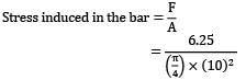
= 12.5 x 10−6 x 20 x 0.5
= 1.25 x 10⁻⁴m
Force induced by the spring due to compression
F = kδ = 50 x 103 x 1.25 x 10−4 = 6.25 N
This stress is compressive for the bar,
∴ Stress = −0.07945 MPa
A steel rod, 2 m long, is held between two walls and heated from 20℃ to 60℃. Young’s modulus and coefficient of linear expansion of rod material are 200 x 103 MPa and 10 x 10−6/℃ respectively. The stress induced in the rod, if walls yield by 0.2 mm, is- a) 60 MPa tensile
- b) 80 MPa tensile
- c) 80 MPa compressive
- d) 60 MPa compressive
Correct answer is option 'D'. Can you explain this answer?
A steel rod, 2 m long, is held between two walls and heated from 20℃ to 60℃. Young’s modulus and coefficient of linear expansion of rod material are 200 x 103 MPa and 10 x 10−6/℃ respectively. The stress induced in the rod, if walls yield by 0.2 mm, is
a)
60 MPa tensile
b)
80 MPa tensile
c)
80 MPa compressive
d)
60 MPa compressive
|
|
Neha Joshi answered |
L = 2 m, t1 = 20° and t2 = 60°

Temperature change (∆t) = t2 − t1 = 40℃
E = 200 x 103 MPa
α = 10 x 10−6/℃
yielding of the wall (λ) = 0.2 mm
BB1 = δth = α(∆t)L
B1 B2 = Expansion restricted by supports
λ = BB2 = yielding of support
= −100[(2000 x 10 x 10−6 x 40) − 0.2]
= −60 MPa = 60 MPa compressive
A cube having each side of length a, is constrained in all directions and is heated uniformly so that the temperature is raised by T℃ . If α is the thermal coefficient of expansion of the cube material and E the modulus of elasticity, the stress developed in the cube is- a) αTE/μ
- b) αTE/(1 − 2μ)
- c) αTE/2μ
- d) αTE/(1 + 2μ)
Correct answer is option 'B'. Can you explain this answer?
A cube having each side of length a, is constrained in all directions and is heated uniformly so that the temperature is raised by T℃ . If α is the thermal coefficient of expansion of the cube material and E the modulus of elasticity, the stress developed in the cube is
a)
αTE/μ
b)
αTE/(1 − 2μ)
c)
αTE/2μ
d)
αTE/(1 + 2μ)

|
Pioneer Academy answered |
Since the cube is restrained in all directions,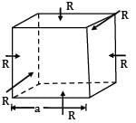
⇒ εv = εx + εy + εz ⋯ ①
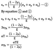
A rigid beam of negligible weight is supported in a horizontal position by two rods of steel and aluminum, 2m and 1m long having values of cross-sectional areas 1 cm2 and 2 cm2 and E of 200 GPa and 100 GPa respectively. A load P is applied as shown in the figure. If the rigid beam is to remain horizontal then
- a) the forces on both sides should be equal
- b) the force on aluminum rod should be twice the force on steel
- c) the force on the steel rod should be twice the force on aluminum
- d) the force p must be applied at the center of the beam
Correct answer is option 'B'. Can you explain this answer?
A rigid beam of negligible weight is supported in a horizontal position by two rods of steel and aluminum, 2m and 1m long having values of cross-sectional areas 1 cm2 and 2 cm2 and E of 200 GPa and 100 GPa respectively. A load P is applied as shown in the figure.
If the rigid beam is to remain horizontal then
a)
the forces on both sides should be equal
b)
the force on aluminum rod should be twice the force on steel
c)
the force on the steel rod should be twice the force on aluminum
d)
the force p must be applied at the center of the beam
|
|
Sarita Yadav answered |
If the beam is to remain horizontal ⇒ δAB = δCD Let force on rod AB be P′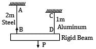
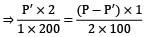
⇒ Force on rod CD = P − P′
⇒ 2P′ = P − P′
⇒ 3P′ = P
⇒ P′ = P/3(force on steel rod) Force on aluminum rod
⇒ Force on aluminum rod
= 2 x force on steel rod.
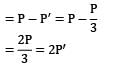
In the arrangement as shown in the figure, the stepped steel bar ABC is loaded by a load P. The material has Young’s modulus E = 200 GPa and the two portions AB and BC have area of cross section 1cm2 and 2cm2 respectively. The magnitude of load P required to fill up the gap of 0.75mm is
- a) 10 kN
- b) 15 kN
- c) 20 kN
- d) 25 kN
Correct answer is option 'B'. Can you explain this answer?
In the arrangement as shown in the figure, the stepped steel bar ABC is loaded by a load P. The material has Young’s modulus E = 200 GPa and the two portions AB and BC have area of cross section 1cm2 and 2cm2 respectively. The magnitude of load P required to fill up the gap of 0.75mm is
a)
10 kN
b)
15 kN
c)
20 kN
d)
25 kN
|
|
Sarita Yadav answered |
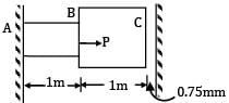
E = 200 GPa = 200 x 103 MPa
AAB = 1 cm2 = 100 mm2
ABC = 2 cm2 = 200 mm2
Gap(δ) = 0.75 mm
There will be no deformation in BC so,
δAB = δ
P = 75 x 200 = 15 x 103N = 15 kN
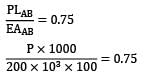
A straight bar is fixed at edges A and B. Its elastic modulus is E and cross-section is A. There is a load P = 120 N acting at C. Determine the reactions at the ends.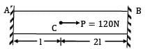
- a) 60 N at A, 60 N at B
- b) 30 N at A, 90 N at B
- c) 40 N at A, 80 N at B
- d) 80 N at A, 40 N at B
Correct answer is option 'D'. Can you explain this answer?
A straight bar is fixed at edges A and B. Its elastic modulus is E and cross-section is A. There is a load P = 120 N acting at C. Determine the reactions at the ends.
a)
60 N at A, 60 N at B
b)
30 N at A, 90 N at B
c)
40 N at A, 80 N at B
d)
80 N at A, 40 N at B
|
|
Neha Joshi answered |
The FBD can be shown as

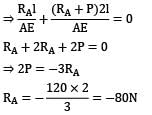
δAC + δCB = 0
(Opposite to the direction assumed)
⇒ RB = −80 + 120 = 40N
If a material had a modulus of elasticity of 2.1 kgf/cm2 and a modulus of rigidity of 0.8 kgf/cm2 then what will be the approximate value of the Poissons ratio?- a)0.26
- b)0.31
- c)0.47
- d)0.43
Correct answer is option 'B'. Can you explain this answer?
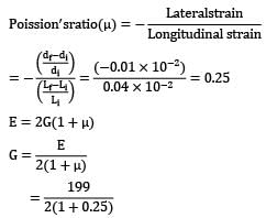
If a material had a modulus of elasticity of 2.1 kgf/cm2 and a modulus of rigidity of 0.8 kgf/cm2 then what will be the approximate value of the Poissons ratio?
a)
0.26
b)
0.31
c)
0.47
d)
0.43

|
Telecom Tuners answered |
On using E = 2G(1 + μ) we can put the values of E and G to get the Poissons value.
The stress state at a point in a material under plane stress condition is equi-biaxial tension with a magnitude of 10 MPa. If one unit on the σ−τ plane is 1 MPa, the Mohr's circle representation of the state-of-stress is given by- a)a circle with a radius equal to principal stress and its center at the origin of the σ−τ plane
- b)a point on the σ axis at a distance of 10 units from the origin
- c)a circle with a radius of 10 units on the σ−τ plane
- d)a point on the τ axis at a distance of 10 units from the origin
Correct answer is option 'B'. Can you explain this answer?
The stress state at a point in a material under plane stress condition is equi-biaxial tension with a magnitude of 10 MPa. If one unit on the σ−τ plane is 1 MPa, the Mohr's circle representation of the state-of-stress is given by
a)
a circle with a radius equal to principal stress and its center at the origin of the σ−τ plane
b)
a point on the σ axis at a distance of 10 units from the origin
c)
a circle with a radius of 10 units on the σ−τ plane
d)
a point on the τ axis at a distance of 10 units from the origin

|
Shalini Deshpande answered |
Explanation:
Equi-biaxial tension state:
- In this case, the stress state at a point in the material is equi-biaxial tension with a magnitude of 10 MPa.
- This means that the stress state is characterized by equal tensile stresses in two perpendicular directions.
Mohr's circle representation:
- When representing the state-of-stress on a σ-τ plane using Mohr's circle, the center of the circle corresponds to the average normal stress and the radius of the circle corresponds to the maximum shear stress.
- In this case, the equi-biaxial tension state has a magnitude of 10 MPa, which means the maximum shear stress is also 10 MPa.
Representation on σ-τ plane:
- Since one unit on the σ-τ plane is 1 MPa, a magnitude of 10 MPa for the equi-biaxial tension state corresponds to a distance of 10 units from the origin along the σ axis.
- Therefore, the Mohr's circle representation of the state-of-stress for this equi-biaxial tension state would be a point on the σ axis at a distance of 10 units from the origin.
Therefore, the correct answer is option 'B' - a point on the σ axis at a distance of 10 units from the origin.
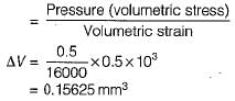
A spherical ball of 0.5 x 103 mm3 volume is subjected to a volumetric stress of 0.5 MPa. If bulk modulus of the bail material is 16 GPa, the change in volume of the ball would be approximately equal to- a)0.0156 mm3
- b)1.56 x 10⁻⁴mm3
- c)0.156 mm3
- d)0.00156 mm3
Correct answer is option 'A'. Can you explain this answer?
A spherical ball of 0.5 x 103 mm3 volume is subjected to a volumetric stress of 0.5 MPa. If bulk modulus of the bail material is 16 GPa, the change in volume of the ball would be approximately equal to
a)
0.0156 mm3
b)
1.56 x 10⁻⁴mm3
c)
0.156 mm3
d)
0.00156 mm3
|
|
Telecom Tuners answered |
Bulk modulus
Youngs modulus of elasticity and Poissons ratio of a material are 1.25 x 10² MPa and 0.34 respectively. The modulus of rigidity of the material is __________- a)0.9469 MPa
- b)0.8375 MPa
- c)0.4664 MPa
- d)0.4025 MPa
Correct answer is option 'C'. Can you explain this answer?
Youngs modulus of elasticity and Poissons ratio of a material are 1.25 x 10² MPa and 0.34 respectively. The modulus of rigidity of the material is __________
a)
0.9469 MPa
b)
0.8375 MPa
c)
0.4664 MPa
d)
0.4025 MPa
|
|
Gate Funda answered |
As E = 2G(1 + μ)
1.25 x 102 = 2G(1 + 0.34)
G = 0.4664 x 10² MPa.
1.25 x 102 = 2G(1 + 0.34)
G = 0.4664 x 10² MPa.
The Young's modulus and the Poisson’s ratio for a certain material are stated to be 1000 GPa and 0.25 respectively. The bulk modulus of the material will be about
- a)450 GPa
- b)600 GPa
- c)66.67 GPa
- d)400 GPa
Correct answer is option 'C'. Can you explain this answer?
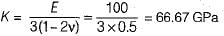
The Young's modulus and the Poisson’s ratio for a certain material are stated to be 1000 GPa and 0.25 respectively. The bulk modulus of the material will be about
a)
450 GPa
b)
600 GPa
c)
66.67 GPa
d)
400 GPa
|
|
Prerna Kaur answered |
E = 3 K ( 1 - 2 v )
A rigid plate ABCD, 1 m2 is supported over four legs of equal lengths of same crosssection and same material. A vertical load 1200 N acts at point E such thatAM = LE = 0.5 mAL = ME = 0.4 mThe reactions RA , RB , RC and RD are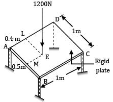
- a) RA = 360N, RB = 360N, RC = 240N, RD = 240N
- b) RA = 240N, RB = 240N, RC = 360N, RD = 360N
- c) RA = 360N, RB = 240N, RC = 360N, RD = 360N
- d) RA = 240N, RB = 360N, RC = 240N, RD = 360N
Correct answer is option 'A'. Can you explain this answer?
A rigid plate ABCD, 1 m2 is supported over four legs of equal lengths of same crosssection and same material. A vertical load 1200 N acts at point E such that
AM = LE = 0.5 m
AL = ME = 0.4 m
The reactions RA , RB , RC and RD are
a)
RA = 360N, RB = 360N, RC = 240N, RD = 240N
b)
RA = 240N, RB = 240N, RC = 360N, RD = 360N
c)
RA = 360N, RB = 240N, RC = 360N, RD = 360N
d)
RA = 240N, RB = 360N, RC = 240N, RD = 360N
|
|
Neha Joshi answered |
For equilibrium RA + RB + RC + RD = 1200 N ⋯ ①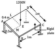

ABCD is a rigid plate, under load, its plane is changed, it is not deformed. Say under load legs deform by δA , δB , δC , δD respectively.
Diagonal AC and diagonal BD remain straight. Centre of the plate lies on both diagonals AC and BD.
δO = deflection at centre of plates
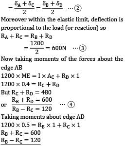
Moreover within the elastic limit, deflection is proportional to the load (or reaction) so
RA + RC = RB + RD
= 1200 / 2
= 600N ⋯ ③
Now taking moments of the forces about the edge AB
1200 x ME = I x AC + RD x 1
1200 x 0.4 = RC + RD
But RC + RD = 480
Taking moments about edge AD
1200 x 0.5 = RB x 1 + RC x 1
RB + RC = 600
RB − RC = 120
RB = 360N
RC = 240N
RA = 600 − RC
RA = 600 − 240 = 360N
RB + RD = 600
RD = 600 − RB
= 600 − 360 = 240N
Finally the reactions are RA = 360N,
RB = 360N, RC = 240N, RD = 240N
An aluminum bar of 8 m length and a steel bar of 5 mm longer in length are kept at 30℃.If the ambient temperature is raised gradually, at what temperature the aluminum bar will elongate 5 mm longer than the steel bar? (The linear expansion coefficients for steel and aluminum are 12 x 10−6/℃ and 23 x 10−6/℃ respectively)- a) 50.7℃
- b) 69.0℃
- c) 143.7℃
- d) 33.7℃
Correct answer is option 'C'. Can you explain this answer?
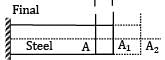
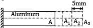
An aluminum bar of 8 m length and a steel bar of 5 mm longer in length are kept at 30℃.If the ambient temperature is raised gradually, at what temperature the aluminum bar will elongate 5 mm longer than the steel bar? (The linear expansion coefficients for steel and aluminum are 12 x 10−6/℃ and 23 x 10−6/℃ respectively)
a)
50.7℃
b)
69.0℃
c)
143.7℃
d)
33.7℃
|
|
Sanvi Kapoor answered |
L = 8 m Initially,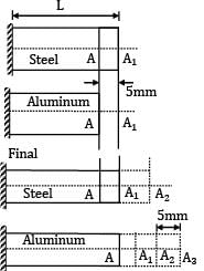
αs = 12 x 10−6/℃
αa = 23 x 10−6/℃
t1 = 30℃
Total elongation of aluminum-total elongation of steel
= (AA3) − (A1A2)
= (AA1) + A1A2 + A2A3) − (A1A2)
= AA1 + A2A3 = 10mm
L αal∆t − Lαs∆t = 10
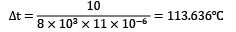
8 x 10³ x ∆t[23 x 10−6 − 12 x 10−6] = 10
t2 − 30° = 113.636℃
t2 = 143.636℃
A tensile specimen with 12 mm initial diameter and 50 mm initial length is subjected to a load of 90 kN. After some time the diameter is 10 mm. Assuming it as incompressible material, Calculate the true strain along the length.
- a)0.34
- b)0.38
- c)0.36
- d)0.32
Correct answer is option 'C'. Can you explain this answer?
A tensile specimen with 12 mm initial diameter and 50 mm initial length is subjected to a load of 90 kN. After some time the diameter is 10 mm. Assuming it as incompressible material, Calculate the true strain along the length.
a)
0.34
b)
0.38
c)
0.36
d)
0.32
|
|
Sarita Yadav answered |
Given,
d1 = 12 mm
l1 = 50 mm p = 90 kN
d2 = 10 mm
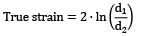
= 0.36
The independent elastic constants for homogeneous and isotropic material are- a)E, G, K, V
- b)E, G, K
- c)E, G, V
- d)E, G
Correct answer is option 'D'. Can you explain this answer?
The independent elastic constants for homogeneous and isotropic material are
a)
E, G, K, V
b)
E, G, K
c)
E, G, V
d)
E, G
|
|
Vibhor Goyal answered |
Only two independent elastic constant are required to express the stress-strain relation for a linearly elastic, isotropic material. We can find third elastic constant and Poisson’s ratio for the material.
A 16 mm diameter bar elongates by 0.04% under a tensile force of 16kN. The average decrease in diameter is found to be 0.01%. Then1. E = 210 GPa and G = 77 GPa2. E = 199 GPa and V = 0.253. E = 199 GPa and V = 0.304. E = 199 GPa and G = 80 GPaWhich of these values are correct?- a) 3 and 4
- b) 2 and 4
- c) 1and 3
- d) 1 and 4
Correct answer is option 'B'. Can you explain this answer?
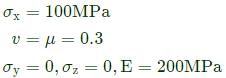
A 16 mm diameter bar elongates by 0.04% under a tensile force of 16kN. The average decrease in diameter is found to be 0.01%. Then
1. E = 210 GPa and G = 77 GPa
2. E = 199 GPa and V = 0.25
3. E = 199 GPa and V = 0.30
4. E = 199 GPa and G = 80 GPa
Which of these values are correct?
a)
3 and 4
b)
2 and 4
c)
1and 3
d)
1 and 4
|
|
Neha Joshi answered |
Load (P) = 16kN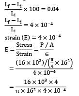
Diameter (d) = 16mm
% elongation = 0.04%
= 198.94 x 10³MPa
= 199 GPa
= 79.6
= 80 GPa
Statement 2 and 4 are correct.
Consider a beam with circular cross-section of diameter d. The ratio of the second moment of area about the neutral axis to the section modulus of the area is.- a)d/2
- b)πd/2
- c)d
- d)πd
Correct answer is option 'A'. Can you explain this answer?
Consider a beam with circular cross-section of diameter d. The ratio of the second moment of area about the neutral axis to the section modulus of the area is.
a)
d/2
b)
πd/2
c)
d
d)
πd
|
|
Mrinalini Sharma answered |
Understanding the Beam Properties
To analyze the properties of a circular cross-section beam, we need to define two key terms: the second moment of area (I) and the section modulus (Z).
Second Moment of Area (I)
- For a circular cross-section with diameter d, the second moment of area about the neutral axis is given by:
I = (π/64) * d^4
Section Modulus (Z)
- The section modulus is derived from the moment of inertia and is used to determine the strength of the beam. For a circular section:
Z = I / (d/2) = (π/32) * d^3
Calculating the Ratio
To find the ratio of the second moment of area to the section modulus, we perform the following calculation:
- Ratio = I / Z
Substituting the expressions for I and Z:
- Ratio = [(π/64) * d^4] / [(π/32) * d^3]
This simplifies to:
- Ratio = (1/2) * d = d/2
Conclusion
Thus, the ratio of the second moment of area to the section modulus for a beam with a circular cross-section of diameter d is indeed d/2, confirming that option 'A' is correct. This relationship is crucial for engineers to understand the beam's ability to resist bending and deflection.
Consider a linear elastic rectangular thin sheet of metal, subjected to uniform uniaxial tensile stress of 100 MPa along the length direction. Assume plane stress conditions in the plane normal to the thickness. The Young's modulus E=200 MPa and Poisson's ratio v=0.3 are given. The principal strains in the plane of the sheet are- a)(0.35, -0.15)
- b)(0.5, 0.0)
- c)(0.5, -0.15)
- d)(0.5, -0.5)
Correct answer is option 'C'. Can you explain this answer?
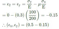
Consider a linear elastic rectangular thin sheet of metal, subjected to uniform uniaxial tensile stress of 100 MPa along the length direction. Assume plane stress conditions in the plane normal to the thickness. The Young's modulus E=200 MPa and Poisson's ratio v=0.3 are given. The principal strains in the plane of the sheet are
a)
(0.35, -0.15)
b)
(0.5, 0.0)
c)
(0.5, -0.15)
d)
(0.5, -0.5)
|
|
Vibhor Goyal answered |
Principal strain in x-direction
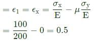
Principal strain in y-direction
A spherical ball of a material of a diameter of 160mm goes down to a depth of 600 m in sea water. If the specific weight of sea water is 10.2kN/m3 and the bulk modulus of the material of the ball is 160kN/mm2, determine the change in volume of ball. - a)80
- b)82
- c)75
- d)62
Correct answer is option 'B'. Can you explain this answer?
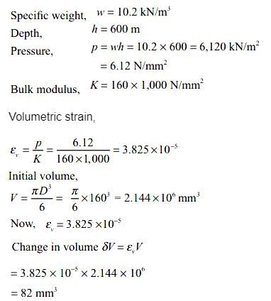
A spherical ball of a material of a diameter of 160mm goes down to a depth of 600 m in sea water. If the specific weight of sea water is 10.2kN/m3 and the bulk modulus of the material of the ball is 160kN/mm2, determine the change in volume of ball.
a)
80
b)
82
c)
75
d)
62
|
|
Vibhor Goyal answered |
If E,G and K have their usual meanings, for an elastic material, then which one of the following be possibly true?- a)G = 2K
- b)G = K
- c)K = E
- d)G = E = K
Correct answer is option 'C'. Can you explain this answer?
If E,G and K have their usual meanings, for an elastic material, then which one of the following be possibly true?
a)
G = 2K
b)
G = K
c)
K = E
d)
G = E = K
|
|
Telecom Tuners answered |
As E = 2G(1 + μ) = 3K(1 – 2μ) = 9KG / (3K + G)
The value of μ must be between 0 to 0.5, so as E never equal to G but if μ = 1/3, then E=K.
The value of μ must be between 0 to 0.5, so as E never equal to G but if μ = 1/3, then E=K.
What will be the value of the Poisson’s ratio if the Youngs modulus E is equal to the bulk modulus K? - a)1/2
- b)1/4
- c)1/3
- d)3/4
Correct answer is option 'C'. Can you explain this answer?
What will be the value of the Poisson’s ratio if the Youngs modulus E is equal to the bulk modulus K?
a)
1/2
b)
1/4
c)
1/3
d)
3/4
|
|
Telecom Tuners answered |
K = E / 3(1 – 2μ)
Since K = E
So (1-2μ) = 1/3
Therefore, μ = 1/3.
Since K = E
So (1-2μ) = 1/3
Therefore, μ = 1/3.
Consider a bar of length L, breadth B and thickness t subjeced to an axial pull or tension P. The resulting volumetric strain will be equal to- a)∈ (1 -2v)
- b)2∈ (1 - v )
- c)∈ (1 + 2v)
- d)3 ∈ v
Correct answer is option 'A'. Can you explain this answer?
Consider a bar of length L, breadth B and thickness t subjeced to an axial pull or tension P. The resulting volumetric strain will be equal to
a)
∈ (1 -2v)
b)
2∈ (1 - v )
c)
∈ (1 + 2v)
d)
3 ∈ v
|
|
Vibhor Goyal answered |

where v is the Poisson’s ratio and ∈ is the longitudinal strain.
Consider the following statements Modulus of rigidity and bulk modulus of a material are found to be 60 GPa and 140 GPa respectively. Then1. elasticity modulus is nearly 200 GPa2. Poisson’s ratio is nearly 0.33. elasticity modulus is nearly 158 GPa4. Poisson’s ratio is nearly 0.25Which of these statements are correct?- a) 1 and 3
- b) 2 and 4
- c) 1 and 4
- d) 2 and 3
Correct answer is option 'D'. Can you explain this answer?
Consider the following statements Modulus of rigidity and bulk modulus of a material are found to be 60 GPa and 140 GPa respectively. Then
1. elasticity modulus is nearly 200 GPa
2. Poisson’s ratio is nearly 0.3
3. elasticity modulus is nearly 158 GPa
4. Poisson’s ratio is nearly 0.25
Which of these statements are correct?
a)
1 and 3
b)
2 and 4
c)
1 and 4
d)
2 and 3
|
|
Avinash Sharma answered |
G = 60 GPa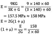
K = 140 GPa
μ = 0.31 ≈ 0.3 Statement 2 and 3 are correct.
At a critical point in a component, the state of stress is given as σxx=100MPa, σyy=220MPa, σxy=σyx=80MPa and all other stress components are zero. The yield strength of the material is 468 MPa. The factor of safety on the basis of maximum shear stress theory is ______ (round off to one decimal place).- a)1.7
- b)0.8
- c)1.2
- d)2.6
Correct answer is option 'A'. Can you explain this answer?
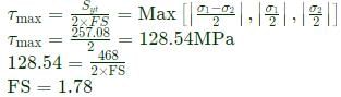
At a critical point in a component, the state of stress is given as σxx=100MPa, σyy=220MPa, σxy=σyx=80MPa and all other stress components are zero. The yield strength of the material is 468 MPa. The factor of safety on the basis of maximum shear stress theory is ______ (round off to one decimal place).
a)
1.7
b)
0.8
c)
1.2
d)
2.6
|
|
Vibhor Goyal answered |
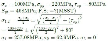
According to maximum shear stress theory,
What is the ratio of Youngs modulus E to shear modulus G in terms of Poissons ratio?- a)2(1 + μ)
- b)2(1 – μ)
- c)1/2 (1 – μ)
- d)1/2 (1 + μ)
Correct answer is option 'C'. Can you explain this answer?
What is the ratio of Youngs modulus E to shear modulus G in terms of Poissons ratio?
a)
2(1 + μ)
b)
2(1 – μ)
c)
1/2 (1 – μ)
d)
1/2 (1 + μ)
|
|
Gate Funda answered |
As we know G = E / 2(1 +μ) so this gives the ratio of E to G = 2(1 + μ).
For an Oldham coupling used between two shafts, which among the following statements are correct?
I. Torsional load is transferred along shaft axis.
II. A velocity ratio of 1:2 between shafts is obtained without using gears.
III. Bending load is transferred transverse to shaft axis.
IV. Rotation is transferred along shaft axis.- a)I and III
- b)I and IV
- c)II and III
- d)II and IV
Correct answer is option 'B'. Can you explain this answer?
For an Oldham coupling used between two shafts, which among the following statements are correct?
I. Torsional load is transferred along shaft axis.
II. A velocity ratio of 1:2 between shafts is obtained without using gears.
III. Bending load is transferred transverse to shaft axis.
IV. Rotation is transferred along shaft axis.
I. Torsional load is transferred along shaft axis.
II. A velocity ratio of 1:2 between shafts is obtained without using gears.
III. Bending load is transferred transverse to shaft axis.
IV. Rotation is transferred along shaft axis.
a)
I and III
b)
I and IV
c)
II and III
d)
II and IV
|
|
Vibhor Goyal answered |
Oldham coupling is used to connect two shafts which are not on the same axis means they are not aligned to the same axis
So,
(1) Torsional load is transferred along shaft axis as both shafts are rotating member.
So, that statement is correct.
(2) A velocity ratio 1:1 between shafts is obtained using gears.
So, this statement is wrong
(3) Bending load is not transferred transverse to shaft axis as there is no transverse load.
(4) Rotation is transferred along shaft axis
So, this statement is correct
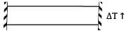
The figure shows a steel piece of diameter 20 mm at A and C, and 10 mm at B. the lengths of three sections A, B and C are each equal to 20 mm. The piece is held between two rigid surface x and Y. The coefficient of linear expansion α = 1.2 x 10⁻⁵ /℃ and Young’s Modulus E = 2 x 10⁵ MPa for steel,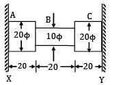 When the temperature of this piece increase by 50℃, the stresses in sections A and B are
- a) 120 MPa and 480 MPa
- b) 60 MPa and 240 MPa
- c) 120 MPa and 120 MPa
- d) 60 MPa and 120 MPa
Correct answer is option 'B'. Can you explain this answer?
The figure shows a steel piece of diameter 20 mm at A and C, and 10 mm at B. the lengths of three sections A, B and C are each equal to 20 mm. The piece is held between two rigid surface x and Y. The coefficient of linear expansion α = 1.2 x 10⁻⁵ /℃ and Young’s Modulus E = 2 x 10⁵ MPa for steel,
When the temperature of this piece increase by 50℃, the stresses in sections A and B are
a)
120 MPa and 480 MPa
b)
60 MPa and 240 MPa
c)
120 MPa and 120 MPa
d)
60 MPa and 120 MPa
|
|
Gate Funda answered |
Α = 1.2 x 10⁻⁵/℃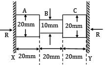
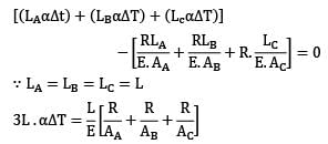
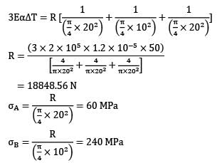
E = 2 x 10⁵ MPa
∆T = 50℃
Since supports are rigid
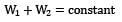
For a composite bar consisting of a bar enclosed inside a tube of another material and when compressed under a load W as a whole through rigid plates at the end of the bar. The equation of compatibility is given by (Suffixes 1 and 2 refer to bar and tube respectively)- a)

- b)
- c)

- d)

Correct answer is option 'C'. Can you explain this answer?
For a composite bar consisting of a bar enclosed inside a tube of another material and when compressed under a load W as a whole through rigid plates at the end of the bar. The equation of compatibility is given by (Suffixes 1 and 2 refer to bar and tube respectively)
a)
b)
c)
d)
|
|
Lavanya Menon answered |
Compatibility condition is
Elongation in bar = Elongation in tube
δ1 = δ2

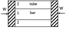
Two tapering bars of the same material are subjected to a tensile load P. The lengths of both the bars are the same. The larger diameter of each of the bars is D. The diameter of the bar A at its smaller end is D/2 and that of the bar b is D/3. What is the ratio of elongation of the bar A to that of the bar B?- a) 3:2
- b) 2:3
- c) 4:9
- d) 1:3
Correct answer is option 'B'. Can you explain this answer?
Two tapering bars of the same material are subjected to a tensile load P. The lengths of both the bars are the same. The larger diameter of each of the bars is D. The diameter of the bar A at its smaller end is D/2 and that of the bar b is D/3. What is the ratio of elongation of the bar A to that of the bar B?
a)
3:2
b)
2:3
c)
4:9
d)
1:3
|
|
Zoya Sharma answered |
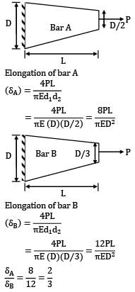
Elongation of bar A
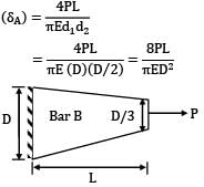
Elongation of bar B

Consider the following statements: The thermal stress is induced in a component in general, when1. a temperature gradient exists in the component2. the component is free from any restraint3. it is restrained to expand or contract freelyWhich of the above statements are correct?- a) 1 and 2
- b) 2 and 3
- c) 3 alone
- d) 2 alone
Correct answer is option 'C'. Can you explain this answer?
Consider the following statements: The thermal stress is induced in a component in general, when
1. a temperature gradient exists in the component
2. the component is free from any restraint
3. it is restrained to expand or contract freely
Which of the above statements are correct?
a)
1 and 2
b)
2 and 3
c)
3 alone
d)
2 alone
|
|
Sanvi Kapoor answered |
1. If a temperature gradient exists in the component, then there will be thermal stresses generated if the component is restrained to expand or contract freely.
2. If the component is free from restraints, no stresses will be generated. However, strain will be there.
3. Thermal stresses will be induced when it is restrained to expand or contract freely.
Ex.: fixed beam with a rise in temperature.
Two circular shafts made of same material, one solid (S) and one hollow (H), have the same length and polar moment of inertia. Both are subjected to same torque. Here, θs is the twist and τs is the maximum shear stress in the solid shaft, whereas θH is the twist and τH is the maximum shear stress in the hollow shaft. Which one of the following is TRUE?- a)θs=θhandτs=τH
- b)θs>θhandτs>τH
- c)θs<θhandτs<τH
- d)θs=θhandτs<τH
Correct answer is option 'D'. Can you explain this answer?
Two circular shafts made of same material, one solid (S) and one hollow (H), have the same length and polar moment of inertia. Both are subjected to same torque. Here, θs is the twist and τs is the maximum shear stress in the solid shaft, whereas θH is the twist and τH is the maximum shear stress in the hollow shaft. Which one of the following is TRUE?
a)
θs=θhandτs=τH
b)
θs>θhandτs>τH
c)
θs<θhandτs<τH
d)
θs=θhandτs<τH

|
Milan Ghosh answered |
Understanding the Problem
Two shafts, one solid (S) and one hollow (H), are subjected to the same torque and have the same polar moment of inertia. The goal is to compare their twists and maximum shear stresses.
Key Concepts
- Twist (θ): The angle of rotation per unit length due to applied torque.
- Maximum Shear Stress (τ): The highest shear stress experienced in the material due to the applied torque.
Formulas for Twisting
- The twist for a circular shaft is given by:
θ = (T * L) / (J * G)
where T is torque, L is length, J is polar moment of inertia, and G is the shear modulus.
Solid vs. Hollow Shaft
- Both shafts have the same polar moment of inertia (J), length (L), and material (same G).
- The solid shaft will have a higher maximum shear stress compared to the hollow shaft, given the same torque.
Comparison of Twists
- Since both shafts have the same J and are subjected to the same torque, they will experience the same twist:
θs = θH.
Comparison of Shear Stresses
- The maximum shear stress in a solid shaft (τs) is higher than that in a hollow shaft (τH) because the solid shaft has more material resisting the torque.
Conclusion
Thus, the correct answer is:
- Option D: θs = θH and τs < τh.="" />
This indicates that while both shafts undergo the same amount of twist, the solid shaft experiences less maximum shear stress than the hollow shaft due to differences in geometry and material distribution.
Consider the following statements:
X. Two-dimensional stresses applied to a thin plater in its own plane represent the plane stress condition.
Y. Normal and shear stresses may occur simultaneously on a plane.
Z. Under plane stress condition, the strain in the direction perpendicular to the plane is zero.
Which of the above statements are correct?- a)2 only
- b)1 and 2
- c)2 and 3
- d)1 and 3
Correct answer is option 'D'. Can you explain this answer?
Consider the following statements:
X. Two-dimensional stresses applied to a thin plater in its own plane represent the plane stress condition.
Y. Normal and shear stresses may occur simultaneously on a plane.
Z. Under plane stress condition, the strain in the direction perpendicular to the plane is zero.
Which of the above statements are correct?
a)
2 only
b)
1 and 2
c)
2 and 3
d)
1 and 3
|
|
Dishani Desai answered |
Understanding Plane Stress Condition
In the context of mechanical engineering, particularly in materials and structural analysis, the following explanations address the correctness of the statements provided.
Statement X: Two-dimensional stresses applied to a thin plate in its own plane represent the plane stress condition.
- This statement is incorrect.
- Plane stress conditions are typically relevant for thin plates subjected to loads in their own plane, but this does not mean that all two-dimensional stresses necessarily imply a plane stress condition.
Statement Y: Normal and shear stresses may occur simultaneously on a plane.
- This statement is correct.
- In mechanics, it is common for both normal and shear stresses to act on a plane simultaneously. This is a fundamental aspect of stress analysis in materials.
Statement Z: Under plane stress condition, the strain in the direction perpendicular to the plane is zero.
- This statement is correct.
- In a plane stress condition, the thickness direction (perpendicular to the plane) experiences negligible stress, which results in zero strain in that direction.
Conclusion
- Based on the analysis above:
- Statements Y and Z are correct, while statement X is incorrect.
- Therefore, the correct answer to the question is option D (1 and 3), as it confirms that Y and Z are valid statements regarding stresses in a plane stress scenario.
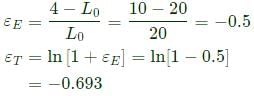
A rod of length 20mm is stretched to make a rod of length 40 mm. Subsequently, it is compressed to make a rod of final length 10 mm. Consider the longitudinal tensile strain as positive and compressive strain as negative. The total true longitudinal strain in the rod is_______- a)-0.5
- b)-0.69
- c)-0.75
- d)-1
Correct answer is option 'B'. Can you explain this answer?
A rod of length 20mm is stretched to make a rod of length 40 mm. Subsequently, it is compressed to make a rod of final length 10 mm. Consider the longitudinal tensile strain as positive and compressive strain as negative. The total true longitudinal strain in the rod is_______
a)
-0.5
b)
-0.69
c)
-0.75
d)
-1
|
|
Vibhor Goyal answered |
For a loaded cantilever beam of uniform cross-section, the bending moment (in N.mm) along the length is M(x)=5x2+10x , where x is the distance (in mm) measured from the free end of the beam. The magnitude of shear force (in N) in the cross-section at x=10 mm is- a)100
- b)105
- c)110
- d)115
Correct answer is option 'C'. Can you explain this answer?
For a loaded cantilever beam of uniform cross-section, the bending moment (in N.mm) along the length is M(x)=5x2+10x , where x is the distance (in mm) measured from the free end of the beam. The magnitude of shear force (in N) in the cross-section at x=10 mm is
a)
100
b)
105
c)
110
d)
115
|
|
Nitin Joshi answered |
Understanding the Problem
For a cantilever beam with a given bending moment function M(x) = 5x² + 10x, we need to find the shear force at a specific point (x = 10 mm) along the beam.
Key Concepts
- Bending Moment (M): Represents the internal moment that causes the beam to bend.
- Shear Force (V): Represents the internal force that acts perpendicular to the beam's axis.
Finding Shear Force
To find the shear force (V) at a position x, we can use the relationship between bending moment and shear force:
V(x) = dM/dx
This means we need to differentiate the bending moment function M(x).
Calculate the Derivative
1. Given M(x) = 5x² + 10x
2. Differentiate M with respect to x:
- dM/dx = 10x + 10
Evaluate Shear Force at x = 10 mm
1. Substitute x = 10 mm into the derivative:
- V(10) = 10(10) + 10
- V(10) = 100 + 10
- V(10) = 110 N
Conclusion
Thus, the magnitude of the shear force at x = 10 mm is 110 N, which corresponds to option 'C'. This calculation confirms the internal force acting on the beam at that point, which is crucial for understanding the beam's structural integrity.
Two steel rods of 20 mm diameter are joined end to end by means of a turn buckle as shown in figure, other end of each rod is rigidly fixed. Initially, there is no tension in each rod. Effective length of each rod is 5 m. Threads on each rod has a pitch of 2.4 mm. Calculate the increase in tension when the turn buckle is tightened by one third of revolution. E = 208 GPa. If the temperature of the rods is increased, then at what temperature, tension in each rod is reduced to half of its magnitude. αs = 11 x 10−6/℃.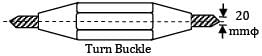
- a) 9.62℃
- b) 7.27℃
- c) 11.63℃
- d) 3.18℃
Correct answer is option 'B'. Can you explain this answer?
Two steel rods of 20 mm diameter are joined end to end by means of a turn buckle as shown in figure, other end of each rod is rigidly fixed. Initially, there is no tension in each rod. Effective length of each rod is 5 m. Threads on each rod has a pitch of 2.4 mm. Calculate the increase in tension when the turn buckle is tightened by one third of revolution. E = 208 GPa. If the temperature of the rods is increased, then at what temperature, tension in each rod is reduced to half of its magnitude. αs = 11 x 10−6/℃.
a)
9.62℃
b)
7.27℃
c)
11.63℃
d)
3.18℃
|
|
Sarita Yadav answered |
A turn buckle is a type of nut having internal threads on two ends but in opposite directions. Ends of tie rods are inserted from both the sides as shown. By rotating the turn buckle, both the tie rods are tightened.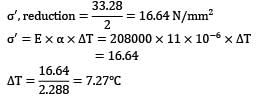
Length of each rod = 5 m Pitch of thread = 2.4 mm
Axial movement of rods on both the sides = 2.4/ 3 = 0.8 mm
Strain in each rod = 0.8 / 5000 = 0.16 x 10⁻³
E = 208000 N/mm2
σ, stress in each rod
= 0.16 x 10−3 x 208 x 1000 = 33.28 N/mm2
Area of cross–section of each rod,
A =π / 4 x 202 = 100 π mm2
Tension in each rod, T = 100π x 33.28
= 10455 N
= 10.455 kN
Tension in rod is to be reduced to half by increasing the temperature of the bar
 (∴ E = K)
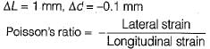
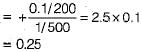
A 50 cm long x 20 cm diameter cylinder of brass was subjected to a tensile load of 0.1 MN. The resulting increase in length and decrease in diameter were noted 1 mm and 0.1 mm respectively. Then the brass has a Poisson’s ratio equal to- a)0.25
- b)0.20
- c)0.26
- d)0.22
Correct answer is option 'A'. Can you explain this answer?
A 50 cm long x 20 cm diameter cylinder of brass was subjected to a tensile load of 0.1 MN. The resulting increase in length and decrease in diameter were noted 1 mm and 0.1 mm respectively. Then the brass has a Poisson’s ratio equal to
a)
0.25
b)
0.20
c)
0.26
d)
0.22

|
Constructing Careers answered |
A rod of length L and diameter D is subjected to a tensile load P. which of the following is sufficient to calculate the resulting change in diameter?- a)Youngs modulus
- b)Poissons ratio
- c)Shear modulus
- d)Both Youngs modulus and shear modulus
Correct answer is option 'A'. Can you explain this answer?
A rod of length L and diameter D is subjected to a tensile load P. which of the following is sufficient to calculate the resulting change in diameter?
a)
Youngs modulus
b)
Poissons ratio
c)
Shear modulus
d)
Both Youngs modulus and shear modulus
|
|
Constructing Careers answered |
For longitudinal strain we need Youngs modulus and for calculating transverse strain we need Poisson’s ratio. We may calculate Poissons ratio from E = 2G(1 + μ) for that we need shear modulus.
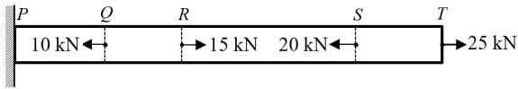
A prismatic bar PQRST is subjected to axial loads as shown in the figure. The segments having maximum and minimum axial stresses, respectively, are
- a)QR and PQ
- b)ST and PQ
- c)QR and RS
- d)ST and RS
Correct answer is option 'D'. Can you explain this answer?
A prismatic bar PQRST is subjected to axial loads as shown in the figure. The segments having maximum and minimum axial stresses, respectively, are
a)
QR and PQ
b)
ST and PQ
c)
QR and RS
d)
ST and RS
|
|
Vibhor Goyal answered |
Pmax= PST= 25kN
Pmin = PRS = 5kN
Hence, maximum and minimum axial stresses are in ST and RS portions because of prismatic bar.
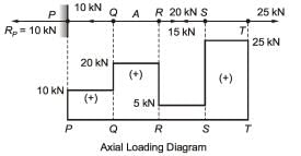
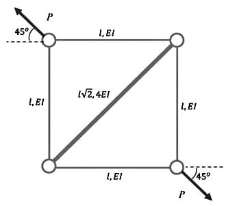
The truss shown in the figure has four members of length l and flexural rigidity EI, and one member of length l√2 and flexural rigidity 4EI. The truss is loaded by a pair of forces of magnitude P, as shown in the figure.
 The smallest value of P, at which any of the truss members will buckle is
- a)

- b)

- c)

- d)

Correct answer is option 'C'. Can you explain this answer?
The truss shown in the figure has four members of length l and flexural rigidity EI, and one member of length l√2 and flexural rigidity 4EI. The truss is loaded by a pair of forces of magnitude P, as shown in the figure.
The smallest value of P, at which any of the truss members will buckle is
a)
b)
c)
d)
|
|
Vibhor Goyal answered |
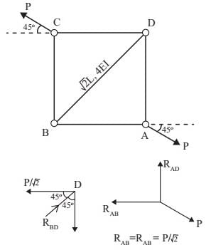
Since buckling will happen due to compression, and it occurs in diagonal only

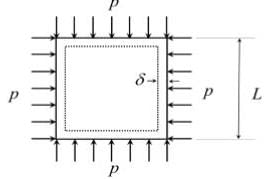
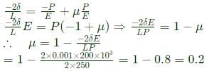
A square plate of dimension L x L is subjected to a uniform pressure load p = 250 MPa on its edges as shown in the figure. Assume plane stress conditions. The Young's modulus E = 200 GPa.
The deformed shape is a square of dimension L−2δ . If L= 2 m and δ=0.001 m, the Poisson's ratio of the plate material is __________- a)0.9
- b)0.8
- c)0.2
- d) 0.7
Correct answer is option 'C'. Can you explain this answer?
A square plate of dimension L x L is subjected to a uniform pressure load p = 250 MPa on its edges as shown in the figure. Assume plane stress conditions. The Young's modulus E = 200 GPa.
The deformed shape is a square of dimension L−2δ . If L= 2 m and δ=0.001 m, the Poisson's ratio of the plate material is __________
The deformed shape is a square of dimension L−2δ . If L= 2 m and δ=0.001 m, the Poisson's ratio of the plate material is __________
a)
0.9
b)
0.8
c)
0.2
d)
0.7
|
|
Vibhor Goyal answered |
Strain in horizontal direction
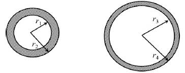
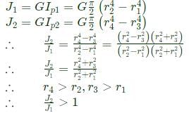
The cross sections of two hollow bars made of the same material are concentric circles as shown in the figure. It is given that r3>r1 and r4>r2 and that the areas of the cross-sections are the same.J1 and J2 are the torsional rigidities of the bars on the left and right, respectively. The ratio J2/J1 is
- a)>1
- b)<0.5
- c)1
- d)between 0.5 and 1
Correct answer is option 'A'. Can you explain this answer?
The cross sections of two hollow bars made of the same material are concentric circles as shown in the figure. It is given that r3>r1 and r4>r2 and that the areas of the cross-sections are the same.J1 and J2 are the torsional rigidities of the bars on the left and right, respectively. The ratio J2/J1 is
a)
>1
b)
<0.5
c)
1
d)
between 0.5 and 1
|
|
Vibhor Goyal answered |
C.S. area of both is same
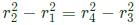
Torsional rigidity
Torsional rigidity
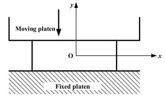
A plane-strain compression (forging) of a block is shown in the figure. The strain in the z-direction is zero. The yield strength (Sy) in uniaxial tension/compression of the material of the block is 300 MPa and it follows the Tresca (maximum shear stress) criterion. Assume that the entire block has started yielding. At a point where σx=40MPa (compressive) and τxy=0, the stress component σy is
- a)340 MPa (compressive)
- b)340 MPa (tensile)
- c)260 MPa (compressive)
- d)260 MPa (tensile)
Correct answer is option 'A'. Can you explain this answer?
A plane-strain compression (forging) of a block is shown in the figure. The strain in the z-direction is zero. The yield strength (Sy) in uniaxial tension/compression of the material of the block is 300 MPa and it follows the Tresca (maximum shear stress) criterion. Assume that the entire block has started yielding. At a point where σx=40MPa (compressive) and τxy=0, the stress component σy is
a)
340 MPa (compressive)
b)
340 MPa (tensile)
c)
260 MPa (compressive)
d)
260 MPa (tensile)
|
|
Vibhor Goyal answered |
In the engineering stress-strain curve for mild steel, the Ultimate Tensile Strength (UTS) refers to- a) Yield stress
- b)Proportional limit
- c)Maximum stress
- d)Fracture stress
Correct answer is option 'C'. Can you explain this answer?
In the engineering stress-strain curve for mild steel, the Ultimate Tensile Strength (UTS) refers to
a)
Yield stress
b)
Proportional limit
c)
Maximum stress
d)
Fracture stress
|
|
Vibhor Goyal answered |
Ultimate tensile strength represents the max. stress that a material can withstand without fracture.
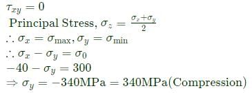
A thin cylindrical pressure vessel with closed-ends is subjected to internal pressure. The ratio of circumferential (hoop) stress to the longitudinal stress is- a)0.25
- b)0.5
- c)1
- d)2
Correct answer is option 'D'. Can you explain this answer?
A thin cylindrical pressure vessel with closed-ends is subjected to internal pressure. The ratio of circumferential (hoop) stress to the longitudinal stress is
a)
0.25
b)
0.5
c)
1
d)
2
|
|
Vibhor Goyal answered |
For thin cylinder
Circumferential stress

Longitudinal stress,
Circumferential stress
Longitudinal stress,
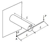
A rigid horizontal rod of length 2L is fixed to a circular cylinder of radius R as shown in the figure. Vertical forces of magnitude P are applied at the two ends as shown in the figure. The shear modulus for the cylinder is G and the Young's modulus is E.
The vertical deflection at point A is- a)PL3/(πR4G)
- b)PL3/(πR4E)
- c)2PL3/(πR4E)
- d)4PL3/(πR4G)
Correct answer is option 'D'. Can you explain this answer?
A rigid horizontal rod of length 2L is fixed to a circular cylinder of radius R as shown in the figure. Vertical forces of magnitude P are applied at the two ends as shown in the figure. The shear modulus for the cylinder is G and the Young's modulus is E.
The vertical deflection at point A is
The vertical deflection at point A is
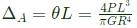
a)
PL3/(πR4G)
b)
PL3/(πR4E)
c)
2PL3/(πR4E)
d)
4PL3/(πR4G)
|
|
Vibhor Goyal answered |
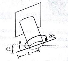
Angle of twist θ
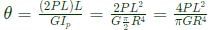
∴ Vertical deflection of A
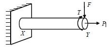
A machine element XY, fixed at end X, is subjected to an axial load P, transverse load F, and a twisting moment T at its free end Y. The most critical point from the strength point of view is
- a)a point on the circumference at location Y
- b)a point at the center at location Y
- c)a point on the circumference at location X
- d)a point at the center at location X
Correct answer is option 'C'. Can you explain this answer?
A machine element XY, fixed at end X, is subjected to an axial load P, transverse load F, and a twisting moment T at its free end Y. The most critical point from the strength point of view is
a)
a point on the circumference at location Y
b)
a point at the center at location Y
c)
a point on the circumference at location X
d)
a point at the center at location X
|
|
Vibhor Goyal answered |
Both bending stress and shear stress (due to torque) will be max at the circumference. The bending stress will be maximum at x. Hence, critical section will be at a point on the circumference at location x.
Chapter doubts & questions for Stress and Strain - 6 Months Preparation for GATE Mechanical 2025 is part of Mechanical Engineering exam preparation. The chapters have been prepared according to the Mechanical Engineering exam syllabus. The Chapter doubts & questions, notes, tests & MCQs are made for Mechanical Engineering 2025 Exam. Find important definitions, questions, notes, meanings, examples, exercises, MCQs and online tests here.
Chapter doubts & questions of Stress and Strain - 6 Months Preparation for GATE Mechanical in English & Hindi are available as part of Mechanical Engineering exam.
Download more important topics, notes, lectures and mock test series for Mechanical Engineering Exam by signing up for free.
6 Months Preparation for GATE Mechanical
499 videos|1037 docs|710 tests
|
|
© EduRev
|
Education Revolution
|


|


Signup to see your scores
go up within 7 days!
Access 1000+ FREE Docs, Videos and Tests
Takes less than 10 seconds to signup