


All Exams >
Electrical Engineering (EE) >
SSC JE Electrical Mock Test Series 2026 >
All Questions
All questions of Electrical Circuits for Electrical Engineering (EE) Exam
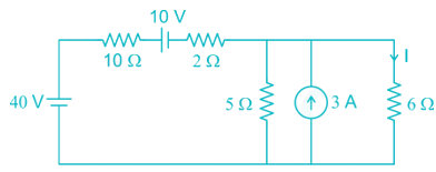
The number of mesh currents required in the circuit given below is: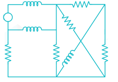
- a)3
- b)4
- c)5
- d)6
Correct answer is option 'C'. Can you explain this answer?
The number of mesh currents required in the circuit given below is:
a)
3
b)
4
c)
5
d)
6

|
Naroj Boda answered |
In the given network
Number of branches (b) = 9
Number of nodes (n) = 5
Number of mesh currents = b – n + 1
= 9 – 5 + 1 = 5

Two heaters rated at 1000 W, 250V each are connected in series across a 250 V, 50 Hz ac mains. The total power drawn from the supply would be _____ watt.- a)1000
- b)500
- c)250
- d)2000
Correct answer is option 'B'. Can you explain this answer?
Two heaters rated at 1000 W, 250V each are connected in series across a 250 V, 50 Hz ac mains. The total power drawn from the supply would be _____ watt.
a)
1000
b)
500
c)
250
d)
2000
|
|
Amar Sengupta answered |
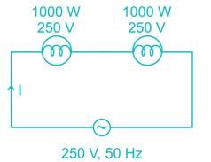
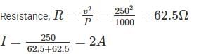
Total power drawn from the supply
P = VI = 250 × 2 = 500 W.

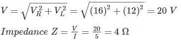
A series RLC circuit has Q of 100 and an impendence of (100 ± j0)Ω at its resonant angular frequency of 107 rad/s. The value of R and L respectively –- a)100 Ω, 10-3H
- b)10 Ω, 102 H
- c)1000 Ω, 10 H
- d)100 Ω, 100 H
Correct answer is option 'A'. Can you explain this answer?
A series RLC circuit has Q of 100 and an impendence of (100 ± j0)Ω at its resonant angular frequency of 107 rad/s. The value of R and L respectively –
a)
100 Ω, 10-3H
b)
10 Ω, 102 H
c)
1000 Ω, 10 H
d)
100 Ω, 100 H
|
|
Sahana Sarkar answered |
ω = 107 rad/s
Q = 100
R = 100 Ω
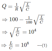
for resonance condition,
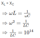
⇒ LC = 10-14 ----(2)
By (1) and (2)
⇒ L = 10-3 H
Three capacitors of 10μF, 20μF and 40μF are connected in parallel across 100 V. The total charge stored in capacitors is:- a)5.9 × 10⁻³ C
- b)4 × 10⁻³ C
- c)7 × 10⁻³ C
- d)14 × 10-3 C
Correct answer is option 'C'. Can you explain this answer?
Three capacitors of 10μF, 20μF and 40μF are connected in parallel across 100 V. The total charge stored in capacitors is:
a)
5.9 × 10⁻³ C
b)
4 × 10⁻³ C
c)
7 × 10⁻³ C
d)
14 × 10-3 C
|
|
Ameya Nambiar answered |
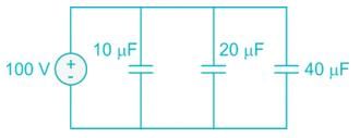
Ceq = 10 + 20 + 40 = 70 μF
Charge, Q = CV = (70 μ F) (100 V) = 7 × 10⁻³ C
A balanced star connected load of 8 + j6 ohms per phase is connected to a 3-phase 230V supply. Power being consumed by the load is.- a)1410.67 W
- b)1269. 6
- c)4232 W
- d)2443.35 W
Correct answer is option 'C'. Can you explain this answer?
A balanced star connected load of 8 + j6 ohms per phase is connected to a 3-phase 230V supply. Power being consumed by the load is.
a)
1410.67 W
b)
1269. 6
c)
4232 W
d)
2443.35 W
|
|
Dipanjan Nambiar answered |
Z = 8 +j 6
Power consumed by the load
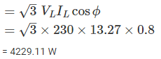
= 4229.11 W
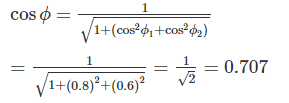
Two circuits having the same magnitudes of impedances are joined in parallel. The power factor of one circuit is 0.8 and of other is 0.6. The power factor of the combination is -- a)0.6
- b)0.75
- c)0.7071
- d)0.8
Correct answer is option 'C'. Can you explain this answer?
Two circuits having the same magnitudes of impedances are joined in parallel. The power factor of one circuit is 0.8 and of other is 0.6. The power factor of the combination is -
a)
0.6
b)
0.75
c)
0.7071
d)
0.8
|
|
Maulik Choudhury answered |
Power factor of first circuit = 0.8 (cos ϕ1)
Power factor of second circuit = 0.6 (cos ϕ2)
The power factor of parallel combination,
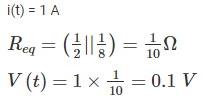
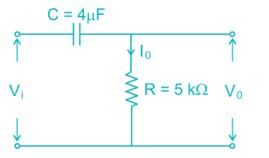
Consider the following given figure and calculate steady-state value of v(t) if i(t) is a unit step current.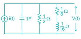
- a)2.5 V
- b)1 V
- c)0.1 V
- d)0
Correct answer is option 'C'. Can you explain this answer?
Consider the following given figure and calculate steady-state value of v(t) if i(t) is a unit step current.
a)
2.5 V
b)
1 V
c)
0.1 V
d)
0
|
|
Mahesh Singh answered |
At steady state inductor acts as short circuit and the capacitor acts as open circuit.
Which of the following is not the same as watt?- a)Joule/sec
- b)(Ampere)2 × ohm
- c)(Volt)2/ohm
- d)Volt/Ampere
Correct answer is option 'D'. Can you explain this answer?
Which of the following is not the same as watt?
a)
Joule/sec
b)
(Ampere)2 × ohm
c)
(Volt)2/ohm
d)
Volt/Ampere
|
|
Jaya Datta answered |
Watt is the unit of power. We can represent the power as follows
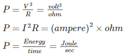
Hence Volt/Ampere is not same as watt, it is equal to ohm.
A circuit consists of three elements connected in series; 10 V battery, 100 Ω and load resistor RL. The maximum power that can be delivered to load would be?- a)1 W
- b)0.25 W
- c)0.5 W
- d)2 W
Correct answer is option 'B'. Can you explain this answer?
A circuit consists of three elements connected in series; 10 V battery, 100 Ω and load resistor RL. The maximum power that can be delivered to load would be?
a)
1 W
b)
0.25 W
c)
0.5 W
d)
2 W
|
|
Jaya Datta answered |
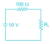
For maximum power transfer, RL = Rth = 100 Ω
Maximumpower 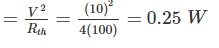
Three wires having conductance’s 2, 3 and 6 mho respectively are connected in parallel in a circuit. The equivalent resistance in the circuit will be:- a)11 ohms
- b)1 ohm
- c)1/11 ohms
- d)33 ohms
Correct answer is option 'C'. Can you explain this answer?
Three wires having conductance’s 2, 3 and 6 mho respectively are connected in parallel in a circuit. The equivalent resistance in the circuit will be:
a)
11 ohms
b)
1 ohm
c)
1/11 ohms
d)
33 ohms

|
Bhargavi Sengupta answered |
Given that,
G1 = 2 mho
G2 = 3 mho
G3 = 6 mho
These are connected in parallel.
Geq = G1 + G2 + G3 + …… + Gn
⇒ Geq = 2 + 3 + 6 = 11 mho
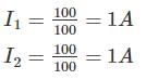
Four resistors of 50 Ω, 50 Ω, 100 Ω and 100 Ω each are connected in parallel across 100 V dc supply. What is the current though each branch if both the resistors of 50 Ω burn out?- a)1 A
- b)6 A
- c)4 A
- d)2 A
Correct answer is option 'A'. Can you explain this answer?
Four resistors of 50 Ω, 50 Ω, 100 Ω and 100 Ω each are connected in parallel across 100 V dc supply. What is the current though each branch if both the resistors of 50 Ω burn out?
a)
1 A
b)
6 A
c)
4 A
d)
2 A

|
Harshad Iyer answered |
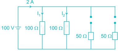
Current flowing through 100 Ω resistance,
If each branch of star connection is 3 Ω. Then its corresponding delta connection will contain ______.- a)3 Ω
- b)1/3Ω
- c)9Ω
- d)1/9Ω
Correct answer is option 'C'. Can you explain this answer?
If each branch of star connection is 3 Ω. Then its corresponding delta connection will contain ______.
a)
3 Ω
b)
1/3Ω
c)
9Ω
d)
1/9Ω
|
|
Rishika Sen answered |
Understanding Star and Delta Connections
In electrical engineering, star (Y) and delta (Δ) connections are two fundamental configurations used to connect three-phase systems. The relationship between resistances in these configurations is critical for circuit analysis.
Star Configuration
- In a star connection, each branch has a resistance of 3 Ω.
- The total resistance between any two phases in a star connection can be calculated using the formula: R_Y = R_phase.
Delta Configuration
- In a delta connection, the resistance is calculated differently. The resistances in the delta configuration are related by the formula: R_Δ = 3 * R_Y.
Calculating Delta Resistance
- Given: R_Y = 3 Ω (each branch in star).
- To find R_Δ:
R_Δ = 3 * R_Y
R_Δ = 3 * 3 Ω
R_Δ = 9 Ω
This indicates that each branch in the delta connection will be 9 Ω.
Conclusion
Thus, when each branch of a star connection has a resistance of 3 Ω, the corresponding resistance in the delta connection will indeed be 9 Ω. The correct answer is option 'C', which is 9 Ω. This relationship is crucial for engineers when converting between these two types of connections in three-phase systems.
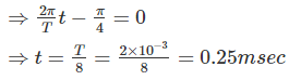
A sinusoidal current is given as i(t) = 150 cos (1000πt – 45°)mA. Determine the period T and time t2 at which the first positive peak occurs:- a)T = 0.2 ms and t1 = 0.35 ms.
- b)T = 2 ms and t1 = 0.25 ms.
- c)T = 1 ms and t1 = 0.35 ms.
- d)T = 0.1 ms and t1 = 0.25 ms.
Correct answer is option 'B'. Can you explain this answer?
A sinusoidal current is given as i(t) = 150 cos (1000πt – 45°)mA. Determine the period T and time t2 at which the first positive peak occurs:
a)
T = 0.2 ms and t1 = 0.35 ms.
b)
T = 2 ms and t1 = 0.25 ms.
c)
T = 1 ms and t1 = 0.35 ms.
d)
T = 0.1 ms and t1 = 0.25 ms.
|
|
Sanaya Basu answered |
i(t) = 150 cos (1000 πt – 45°) mA
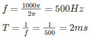
i(t) can attain max at
1000πt - π/4 = 0
What is the difference between an atom and an ion?- a)Ions have always larger mass than the atoms of the same element
- b)Ions are neutral particles while atoms always carry a positive charge
- c)Ions are always charged particles while the atoms are neutral as a whole
- d)Ions can only exist in liquid solutions
Correct answer is option 'C'. Can you explain this answer?
What is the difference between an atom and an ion?
a)
Ions have always larger mass than the atoms of the same element
b)
Ions are neutral particles while atoms always carry a positive charge
c)
Ions are always charged particles while the atoms are neutral as a whole
d)
Ions can only exist in liquid solutions
|
|
Pranab Basu answered |
An ion is a particle or collection of particles with a net positive or negative charge.
An atom is the basic unit of an element. The identity of an element is determined by the number of positively charged protons in the atom’s nucleus. A stable atom contains the same number of electrons as protons and no net charge.
Which statement about electrical network and electrical circuit is CORRECT?- a)Electrical network and electrical circuit are same
- b)Electrical network and electrical circuit are different
- c)Every electrical circuit is a network, but all networks are not circuits
- d)Every network is a circuit
Correct answer is option 'C'. Can you explain this answer?
Which statement about electrical network and electrical circuit is CORRECT?
a)
Electrical network and electrical circuit are same
b)
Electrical network and electrical circuit are different
c)
Every electrical circuit is a network, but all networks are not circuits
d)
Every network is a circuit
|
|
Prasad Verma answered |
Explanation:
Difference between Electrical Network and Electrical Circuit:
- Electrical network and electrical circuit are different:
- An electrical network is a collection of interconnected components (such as resistors, capacitors, and inductors) where each component is represented by a node and the connections between components are represented by branches.
- An electrical circuit, on the other hand, is a closed loop path that contains a power source and various components connected in a specific way to perform a specific function.
- Every electrical circuit is a network, but all networks are not circuits:
- Every electrical circuit is essentially an electrical network because it consists of interconnected components.
- However, not all networks can be considered circuits as they may not form a closed loop path or may not have a power source to perform a specific function.
- Examples:
- A simple series circuit with a battery, resistor, and connecting wires is both an electrical circuit and an electrical network.
- A complex network of interconnected components without a closed loop path or power source may be considered an electrical network but not a circuit.
In conclusion, while every electrical circuit is a network due to its interconnected components, not all networks can be classified as circuits as they may lack the necessary elements to form a complete functional loop.
Given condition justifies which network theorems- the load impedance should be complex conjugate of the internal impedance of the active network.- a)Reciprocity theorem
- b)Maximum power transfer theorem
- c)Millman’s theorem
- d)Compensation theorem
Correct answer is option 'B'. Can you explain this answer?
Given condition justifies which network theorems- the load impedance should be complex conjugate of the internal impedance of the active network.
a)
Reciprocity theorem
b)
Maximum power transfer theorem
c)
Millman’s theorem
d)
Compensation theorem
|
|
Prisha Iyer answered |
According to maximum power transfer theorem, in AC circuits the load impedance should be complex conjugate of the internal impedance of the active network

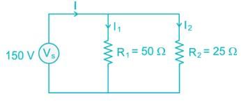
A voltage source and two resistors are connected in parallel. Suppose that Vs = 150V, R1 = 50Ω and R2 = 25Ω. Then each resistance contain current?- a)i1 = 3A and i2 = 6A
- b)i1 = 6A and i2 = 3A
- c)i1 = 3A and i2 = 2A
- d)i1 = 2A and i2 = 3A
Correct answer is option 'A'. Can you explain this answer?
A voltage source and two resistors are connected in parallel. Suppose that Vs = 150V, R1 = 50Ω and R2 = 25Ω. Then each resistance contain current?
a)
i1 = 3A and i2 = 6A
b)
i1 = 6A and i2 = 3A
c)
i1 = 3A and i2 = 2A
d)
i1 = 2A and i2 = 3A
|
|
Sanchita Sharma answered |
In a four-branch parallel circuit, there are 10 mA of current in each branch. If one of the branches is open, the current in each of the other three branches is:- a)13.3 mA
- b)10 mA
- c)0 A
- d)30 mA
Correct answer is option 'B'. Can you explain this answer?
In a four-branch parallel circuit, there are 10 mA of current in each branch. If one of the branches is open, the current in each of the other three branches is:
a)
13.3 mA
b)
10 mA
c)
0 A
d)
30 mA
|
|
Akanksha Tiwari answered |
All the four branches are connected in parallel, so the voltage across every branch is same. If one of the branch is open, it doesn’t affect the other branches current. Because the voltage and impedance across remaining branches will remain same.
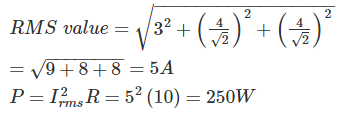
The current i(t), through a 10 Ω resistor in series with an inductance is given by I(t) = 3 + 4 sin(100t + 450) + 4sin(300t + 600) amperes the RMS values of the current and power dissipation in the circuit are- a)√41 A, 410 W respectively
- b)√45 A, 350 W respectively
- c)5 A, 250 W respectively
- d)11 A, 1210 W respectively
Correct answer is option 'C'. Can you explain this answer?
The current i(t), through a 10 Ω resistor in series with an inductance is given by I(t) = 3 + 4 sin(100t + 450) + 4sin(300t + 600) amperes the RMS values of the current and power dissipation in the circuit are
a)
√41 A, 410 W respectively
b)
√45 A, 350 W respectively
c)
5 A, 250 W respectively
d)
11 A, 1210 W respectively
|
|
Vaishnavi Singh answered |
A filament lamp of 40 W, 110 V is connected in series with resistance R. if the supply voltage is 230 V, the value of resistance R should be:- a)330 ohm
- b)340 ohm
- c)130 ohm
- d)240 ohm
Correct answer is option 'A'. Can you explain this answer?
A filament lamp of 40 W, 110 V is connected in series with resistance R. if the supply voltage is 230 V, the value of resistance R should be:
a)
330 ohm
b)
340 ohm
c)
130 ohm
d)
240 ohm
|
|
Sakshi Roy answered |
Given data:
- Power of the filament lamp (P) = 40 W
- Voltage across the lamp (V) = 110 V
- Supply voltage (Vs) = 230 V
Calculating resistance of the filament lamp:
Using the formula P = V^2 / R, we can calculate the resistance of the filament lamp:
R = V^2 / P
R = (110)^2 / 40
R = 302.5 ohm
Calculating the resistance in series with the lamp:
Let the resistance in series with the lamp be R.
Total voltage across the circuit = Voltage across lamp + Voltage across R
Vs = V + V_R
230 = 110 + 110 + R
R = 230 - 220
R = 330 ohm
Therefore, the value of resistance R should be 330 ohm to be connected in series with the filament lamp.
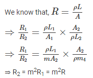
If the length of a wire having uniform resistance R is stretched in m times with volume remaining same. What will be new resistance value?- a)R/m
- b)Rm2
- c)mR
- d)R/m2
Correct answer is option 'B'. Can you explain this answer?
If the length of a wire having uniform resistance R is stretched in m times with volume remaining same. What will be new resistance value?
a)
R/m
b)
Rm2
c)
mR
d)
R/m2
|
|
Vaibhav Mukherjee answered |
Given that, the length of a wire having uniform resistance R is stretched in m times with volume remaining same.
Let the length of the wire is L1
and the area of the wire is A1
For volume remains to be same
L1A1 = L2A2
⇒ L1A1 = (mL1) (A2)
⇒ A1 = mA2
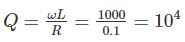
What will be the bandwidth of a series resonant circuit provided it has an inductive reactance of 1000 Ohm, a capacitive reactance of 1000 Ohm a resistance of 0.1 Ohm? It also know that the resonant frequency is 10MHz.- a)1 kHz
- b)10 kHz
- c)1 MHz
- d)0.1 kHz
Correct answer is option 'A'. Can you explain this answer?
What will be the bandwidth of a series resonant circuit provided it has an inductive reactance of 1000 Ohm, a capacitive reactance of 1000 Ohm a resistance of 0.1 Ohm? It also know that the resonant frequency is 10MHz.
a)
1 kHz
b)
10 kHz
c)
1 MHz
d)
0.1 kHz
|
|
Bijoy Nair answered |
Given that, XL = 1000 Ω
XC = 1000 Ω
R = 0.1 Ω
F0 = 10 MHz
For parallel RLC circuit, which of the following statements is not correct?- a)The bandwidth of the circuit decreases, if R is increased
- b)The bandwidth of the circuit remains the same, if L is increased
- c)At resonance, input impedance is a real quantity
- d)At resonance, the magnitude of input impedance attains its minimum value
Correct answer is option 'D'. Can you explain this answer?
For parallel RLC circuit, which of the following statements is not correct?
a)
The bandwidth of the circuit decreases, if R is increased
b)
The bandwidth of the circuit remains the same, if L is increased
c)
At resonance, input impedance is a real quantity
d)
At resonance, the magnitude of input impedance attains its minimum value
|
|
Bijoy Mehta answered |
Parallel RLC Circuit and Bandwidth
A parallel RLC circuit consists of a resistor (R), an inductor (L), and a capacitor (C) connected in parallel. This type of circuit is commonly used in various electrical systems and applications. One of the important characteristics of a parallel RLC circuit is its bandwidth, which refers to the range of frequencies over which the circuit operates effectively.
Bandwidth and Resistance (Option A)
When the resistance (R) in a parallel RLC circuit is increased, it affects the circuit's bandwidth. The bandwidth is defined as the difference between the upper and lower cutoff frequencies, where the circuit's response decreases by a specified amount (usually -3 dB). As the resistance increases, the circuit becomes more damped, resulting in a decrease in the bandwidth. Therefore, option A is correct.
Bandwidth and Inductance (Option B)
Increasing the inductance (L) in a parallel RLC circuit does not affect the circuit's bandwidth. The bandwidth is primarily determined by the resistance and capacitance values in the circuit. The inductance affects the resonant frequency but does not directly impact the bandwidth. Therefore, option B is incorrect.
Input Impedance and Resonance (Option C)
At resonance, the input impedance of a parallel RLC circuit becomes a real quantity. Resonance occurs when the inductive reactance (XL) is equal to the capacitive reactance (XC). At this frequency, the imaginary components cancel each other out, resulting in a purely resistive impedance. Therefore, option C is correct.
Input Impedance at Resonance (Option D)
Option D states that at resonance, the magnitude of the input impedance attains its minimum value. This statement is incorrect. At resonance, the magnitude of the input impedance in a parallel RLC circuit is at its maximum value, not minimum. The impedance is purely resistive at resonance, and its magnitude is determined by the resistance value. Therefore, option D is incorrect.
Conclusion
In summary, option D is the incorrect statement regarding a parallel RLC circuit. At resonance, the magnitude of the input impedance is at its maximum value, not minimum. The correct statements are:
- The bandwidth of the circuit decreases if the resistance is increased.
- The bandwidth of the circuit remains the same if the inductance is increased.
- At resonance, the input impedance is a real quantity.
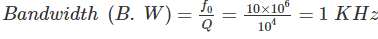
A lamp rated at 60V, 40W is to be connected across 230V. What is the value of resistance to be connected in series with lamp?- a)100Ω
- b)255Ω
- c)90Ω
- d)345Ω
Correct answer is option 'B'. Can you explain this answer?
A lamp rated at 60V, 40W is to be connected across 230V. What is the value of resistance to be connected in series with lamp?
a)
100Ω
b)
255Ω
c)
90Ω
d)
345Ω
|
|
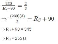
Saumya Basak answered |
Rating of lamp = 60V, 40 W
When lamp is connected, maximum current that can be flow through the circuit is

Let RS be the series resistance.
The sum of currents entering a junction is 9 A. If the current leaves the junction form 3 different paths having the same resistance, the current leaving from any one of the path will be:- a)1 A
- b)9 A
- c)3 A
- d)It cannot be determined
Correct answer is option 'C'. Can you explain this answer?
The sum of currents entering a junction is 9 A. If the current leaves the junction form 3 different paths having the same resistance, the current leaving from any one of the path will be:
a)
1 A
b)
9 A
c)
3 A
d)
It cannot be determined
|
|
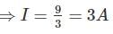
Sahana Sarkar answered |
By KCL,
The sum of current entering a junction is equal to the sum of current leaving at that junction.
⇒ Sum of currents leaving = 9 A
This 9 A current will flow through three resistances having same value.
The current will be some through each resistor
A series resonant circuit has R = 2Ω, L = 1mH and C = 0.1 μF, the value of quality factor Q is:- a)40
- b)50
- c)25
- d)30
Correct answer is option 'B'. Can you explain this answer?
A series resonant circuit has R = 2Ω, L = 1mH and C = 0.1 μF, the value of quality factor Q is:
a)
40
b)
50
c)
25
d)
30
|
|
Sahana Sarkar answered |
Given that, R = 2 Ω, L = 1 mH, C = 0.1 μ F
For series resonant circuit,
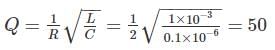
An ac voltage is described by v(t) = 10 cos (400 πt), find out frequency and RMS value of voltage.- a)400 Hz, 7.07V
- b)400 Hz, 14.14V
- c)200 Hz, 14.14V
- d)200 Hz, 7.07V
Correct answer is option 'D'. Can you explain this answer?
An ac voltage is described by v(t) = 10 cos (400 πt), find out frequency and RMS value of voltage.
a)
400 Hz, 7.07V
b)
400 Hz, 14.14V
c)
200 Hz, 14.14V
d)
200 Hz, 7.07V
|
|
Sparsh Nambiar answered |
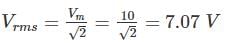
V(t) = 10 cos (400 π t)
ω = 400 π
⇒ 2 π f = 400 π
⇒ f = 200 Hz
Vm = 10 V
If the energy is supplied form a source, whose resistance is 1 Ohm, to a load of 100 Ohms the source will be- a)A voltage source
- b)A current source
- c)Both a above
- d)None of the above
Correct answer is option 'A'. Can you explain this answer?
If the energy is supplied form a source, whose resistance is 1 Ohm, to a load of 100 Ohms the source will be
a)
A voltage source
b)
A current source
c)
Both a above
d)
None of the above
|
|
Sanchita Sharma answered |
The internal resistance of an ideal voltage source should be zero and practically it is very low.
Given that, source resistance is 1 ohm
Hence the source will be a voltage source

A voltage source of 10 V and resistor are connected in series. Specify the resistance R so that both of the following conditions are satisfied:i > 40 mA and the power absorbed by the resistors is < 0.5 W.- a)260 Ω
- b)250 Ω
- c)220 Ω
- d)200 Ω
Correct answer is option 'C'. Can you explain this answer?
A voltage source of 10 V and resistor are connected in series. Specify the resistance R so that both of the following conditions are satisfied:
i > 40 mA and the power absorbed by the resistors is < 0.5 W.
a)
260 Ω
b)
250 Ω
c)
220 Ω
d)
200 Ω
|
|
Akash Mukherjee answered |
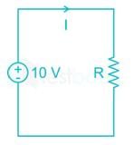
Given that,
I > 40 mA
⇒ R > 200
⇒ 200 < R < 250
Which of the following statements is/are correct about Norton Theorem?A) The value of the current source is the short circuit current between the two terminals of the network.B) Resistance is the equivalent resistance measured between the terminals of the network with all the energy. Sources are replaced by their internal resistance.- a)Only A is correct
- b)Only B is correct
- c)Both A and B is correct
- d)Both A and B is incorrect
Correct answer is option 'C'. Can you explain this answer?
Which of the following statements is/are correct about Norton Theorem?
A) The value of the current source is the short circuit current between the two terminals of the network.
B) Resistance is the equivalent resistance measured between the terminals of the network with all the energy. Sources are replaced by their internal resistance.
a)
Only A is correct
b)
Only B is correct
c)
Both A and B is correct
d)
Both A and B is incorrect
|
|
Ritika Mukherjee answered |
Norton’s network for any given network can be represented as
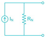
The value of the current source is the short circuit current between the two terminals of the network
Norton’s Resistance is the equivalent resistance measured between the terminals of the network with all the energy. Sources are replaced by their internal resistance.
An ac voltage has frequency of 50 Hz with peak amplitude of 100 V. In how many seconds after the zero value, voltage will attain the value of 86.6 V?- a)1/300 second
- b)1/100 second
- c)1/150 second
- d)1/600 second
Correct answer is option 'A'. Can you explain this answer?
An ac voltage has frequency of 50 Hz with peak amplitude of 100 V. In how many seconds after the zero value, voltage will attain the value of 86.6 V?
a)
1/300 second
b)
1/100 second
c)
1/150 second
d)
1/600 second
|
|
Dipanjan Nambiar answered |
Given data:
Frequency of ac voltage = 50 Hz
Peak amplitude = 100 V
Required voltage = 86.6 V
Calculation:
The ac voltage can be represented by the equation:
V(t) = V_m * sin(ωt)
Where:
V(t) = instantaneous voltage at time t
V_m = peak amplitude of the voltage
ω = angular frequency = 2πf
t = time
In this case, V_m = 100 V and f = 50 Hz, so ω = 2π * 50 = 100π rad/s.
We need to find the time at which the voltage attains the value of 86.6 V.
So, we can set up the equation:
86.6 = 100 * sin(100πt)
To solve this equation, we can rearrange it as:
sin(100πt) = 0.866
Using the inverse sine function, we can find the time:
sin^(-1)(sin(100πt)) = sin^(-1)(0.866)
100πt = sin^(-1)(0.866)
t = (sin^(-1)(0.866)) / (100π)
Now, we can calculate the value of t using a calculator:
t ≈ 0.01 seconds
Therefore, the voltage will attain the value of 86.6 V after approximately 0.01 seconds.
Answer:
The correct option is (A) 1/300 second.
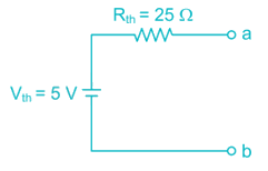
For a network Thevenin equivalent is given by Vth = 10 V and Rth = 50 Ω. If this network is shunted by another 50 Ω ……… at load. What is the new Thevenin equivalent of the network?- a)5 V, 50 Ω
- b)5 V, 25 Ω
- c)10 V, 50 Ω
- d)10 V, 25 Ω
Correct answer is option 'B'. Can you explain this answer?
For a network Thevenin equivalent is given by Vth = 10 V and Rth = 50 Ω. If this network is shunted by another 50 Ω ……… at load. What is the new Thevenin equivalent of the network?
a)
5 V, 50 Ω
b)
5 V, 25 Ω
c)
10 V, 50 Ω
d)
10 V, 25 Ω
|
|
Maulik Choudhury answered |
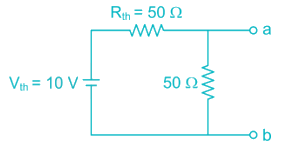
Now voltage across terminal a - b is
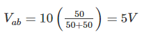
The Thevenin’s resistance can be find by neglecting the voltages source.
Rab = 25 Ω
New Thevenin equivalent network is,
An inductive coil of 0.2 H is connected to 200 V, 50 Hz source. What are the inductive reactance and RMS current in the circuit?- a)62.83Ω, 3.18 A
- b)31.42Ω, 6.37 A
- c)0.2Ω, 2000 A
- d)31.42Ω, 2000 A
Correct answer is option 'A'. Can you explain this answer?
An inductive coil of 0.2 H is connected to 200 V, 50 Hz source. What are the inductive reactance and RMS current in the circuit?
a)
62.83Ω, 3.18 A
b)
31.42Ω, 6.37 A
c)
0.2Ω, 2000 A
d)
31.42Ω, 2000 A
|
|
Sanchita Sharma answered |
Given that, inductance = 0.2 H
Voltage = 200 V
Inductive reactance = 2 π fL = 2 π × 50 × 0.2 = 62.8 Ω
The voltage source in the given circuit supplies 24W of power. The current source supplies 6.0 W. Determine the value of the resistance R1 and R2: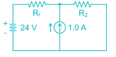
- a)R1 = 24Ω and R2 = 2.5Ω
- b)R1 = 18Ω and R2 = 3.0Ω
- c)R1 = 24Ω and R2 = 3.0Ω
- d)R1 = 18Ω and R2 = 2.5Ω
Correct answer is option 'B'. Can you explain this answer?
The voltage source in the given circuit supplies 24W of power. The current source supplies 6.0 W. Determine the value of the resistance R1 and R2:
a)
R1 = 24Ω and R2 = 2.5Ω
b)
R1 = 18Ω and R2 = 3.0Ω
c)
R1 = 24Ω and R2 = 3.0Ω
d)
R1 = 18Ω and R2 = 2.5Ω
|
|
Dipanjan Nambiar answered |
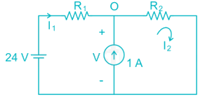
Given that, voltage source supplies 24 W
By applying KVL,
- 24 + I1 R1 + I2 R2 = 0
⇒ I2 R2 = 24 – R1 → (1)
Given that, current source supplies 6 W
By KVL in second loop
I2 R2 = 6 → (2)
From (1) and (2)
⇒ R1 = 18 Ω
By KCL at point ‘O’
⇒ I2 = 1 + I1 = 2 A
We know that, I2 R2 = 6
⇒ R2 = 3 Ω
Find the value of Req in the figure given below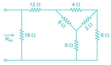
- a)18Ω
- b)

- c)

- d)9 Ω
Correct answer is option 'D'. Can you explain this answer?
Find the value of Req in the figure given below
a)
18Ω
b)
c)
d)
9 Ω
|
|
Sahana Sarkar answered |
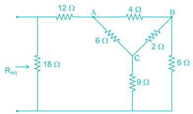
By converting Delta (ABC) in to star
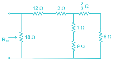
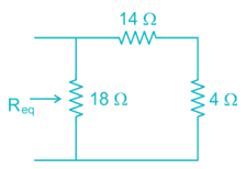
Req = 18 || (14 + 4) = 9 Ω
The temperature coefficient of resistance of material is given as: - a)

- b)

- c)

- d)

Correct answer is option 'A'. Can you explain this answer?
The temperature coefficient of resistance of material is given as:
a)
b)
c)
d)
|
|
Maulik Choudhury answered |
We know that, R = R0[1+α(T1−T2)]
Where α is a temperature coefficient of resistance
If the temperature coefficient of resistance is positive, it indicates that the resistance increases with the increase in temperature
If the temperature coefficient of resistance is negative, it indicates that the resistance decreases with the increase in temperature
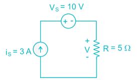
A current source and a voltage source are connected in series with a resistor as shown below. Suppose that Vs = 10V, is = 3A and R = 5Ω. What is the voltage across the resistor and the power absorbed by the resistor?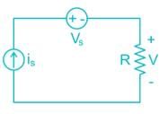
- a)15V and 45 W
- b)10 V and 20 W
- c)15 V and 20 W
- d)10 V and 45 W
Correct answer is option 'A'. Can you explain this answer?
A current source and a voltage source are connected in series with a resistor as shown below. Suppose that Vs = 10V, is = 3A and R = 5Ω. What is the voltage across the resistor and the power absorbed by the resistor?
a)
15V and 45 W
b)
10 V and 20 W
c)
15 V and 20 W
d)
10 V and 45 W
|
|
Mainak Pillai answered |
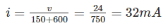
Determine the value of the current i for the circuit shown below.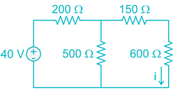
- a)32 mA
- b)25 mA
- c)20 mA
- d)30 mA
Correct answer is option 'A'. Can you explain this answer?
Determine the value of the current i for the circuit shown below.
a)
32 mA
b)
25 mA
c)
20 mA
d)
30 mA
|
|
Yashvi Shah answered |
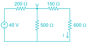
Apply nodal analysis at node v.
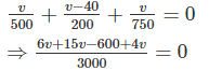
⇒ 25V = 600
⇒ v = 24
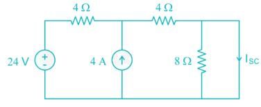
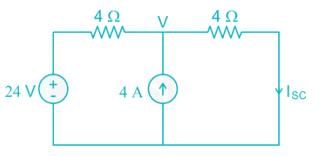
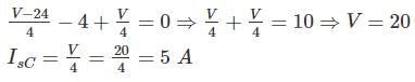
The Norton current at terminals a and b of the circuit shown at Figure:
- a)1 A
- b)-2 A
- c)2 A
- d)3 A
Correct answer is option 'A'. Can you explain this answer?
The Norton current at terminals a and b of the circuit shown at Figure:
a)
1 A
b)
-2 A
c)
2 A
d)
3 A
|
|
Megha Datta answered |
To find Norton’s current, we need to find the short circuit current across the terminals a and b.
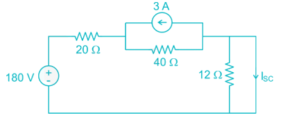
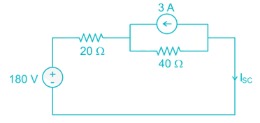
By source transformation,
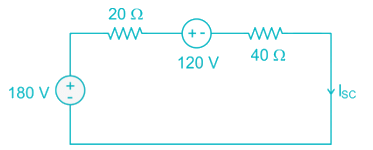
By KVL,
-180 + 20 ISC + 120 +40 ISC = 0
⇒ ISC = 1 A
In an a.c. circuit, v = 50sin(ωt+60∘),i = 10cos(ωt)then the power factor of a.c. circuit will be:- a)0.5 lag
- b)0.5 lead
- c)0.866 lag
- d)0.866 lead
Correct answer is option 'D'. Can you explain this answer?
In an a.c. circuit, v = 50sin(ωt+60∘),i = 10cos(ωt)then the power factor of a.c. circuit will be:
a)
0.5 lag
b)
0.5 lead
c)
0.866 lag
d)
0.866 lead
|
|
Aditya Basu answered |
Given that, V = 50 sin (ω t + 60°)
i = 10 cos (ω t)
i = 10 cos (ω t)
i = 10 sin (ω t + 90°)
i is leading V
Phase difference (ϕ) = 30°
Consider the following circuit and find the current through the 6Ω resistor.
- a)1.23 A
- b)2.03 A
- c)1.11 A
- d)0.31 A
Correct answer is option 'B'. Can you explain this answer?
Consider the following circuit and find the current through the 6Ω resistor.
a)
1.23 A
b)
2.03 A
c)
1.11 A
d)
0.31 A
|
|
Kalyan Patel answered |
Let the current passing through 6 Ω resistor is I.
By source transformation,
By source transformation,
By current division, 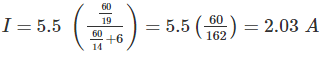
Find the average current flow in the wire.Given: type of wire: metallicTotal electrons drift across section per second = 1020- a)1.5 A
- b)1.6 A
- c)15 A
- d)16 A
Correct answer is option 'D'. Can you explain this answer?
Find the average current flow in the wire.
Given: type of wire: metallic
Total electrons drift across section per second = 1020
a)
1.5 A
b)
1.6 A
c)
15 A
d)
16 A
|
|
Ritika Mukherjee answered |
Total electrons drift across section power second = 1020
We know that, q = it
For t = 1 sec
⇒ q = i
⇒ i = q = ne = 1020 × 1.6 × 10-19 = 16 A
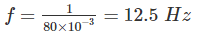
Express the voltage shown below in the general form v(t) = Vm sin (ωt + θ).
- a)v(t) = 45 sin (12.5 πt + 0)
- b)v(t) = 45 sin (25 πt + 90°)
- c)v(t) = 45 sin (12.5 πt + 90°)
- d)v(t) = 45 sin (25 πt + 0)
Correct answer is option 'D'. Can you explain this answer?
Express the voltage shown below in the general form v(t) = Vm sin (ωt + θ).
a)
v(t) = 45 sin (12.5 πt + 0)
b)
v(t) = 45 sin (25 πt + 90°)
c)
v(t) = 45 sin (12.5 πt + 90°)
d)
v(t) = 45 sin (25 πt + 0)
|
|
Ritika Mukherjee answered |
V(t) = Vm sin (ωt + θ)
From the given wave form,
Vm = 45
Time period, T = 80 ms
ω = 2πf = 25 π
V(t) = 45 sin (25 πt + 0)
The Thevenin equivalent resistance (RTh) for the circuit shown in fig. is: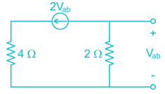
- a)4Ω
- b)0.4Ω
- c)0.5Ω
- d)2Ω
Correct answer is option 'B'. Can you explain this answer?
The Thevenin equivalent resistance (RTh) for the circuit shown in fig. is:
a)
4Ω
b)
0.4Ω
c)
0.5Ω
d)
2Ω
|
|
Mainak Roy answered |
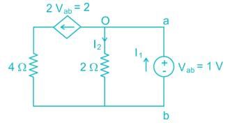
By KCL at point ‘O’
I1 = I2 + 2 = 0.5 + 2 = 2.5
Applying Norton’s Theorem, the Norton’s equivalent circuit to the left of the terminals “a” and “b” in the below circuit is having equivalent current source (IN) and equivalent resistance (RN)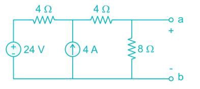
- a)5 Ampere, 4 Ohm
- b)4 Ampere, 6 Ohm
- c)9 Ampere, 1.6 Ohm
- d)4 Ampere, 3 Ohm
Correct answer is option 'A'. Can you explain this answer?
Applying Norton’s Theorem, the Norton’s equivalent circuit to the left of the terminals “a” and “b” in the below circuit is having equivalent current source (IN) and equivalent resistance (RN)
a)
5 Ampere, 4 Ohm
b)
4 Ampere, 6 Ohm
c)
9 Ampere, 1.6 Ohm
d)
4 Ampere, 3 Ohm
|
|
Sanchita Sharma answered |
To find Norton’s resistance, we need to short circuit the voltage source and open circuit the current source
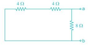
RN = (4 + 4) || 8 = 4 Ω
To find the Norton’s current, we need to find short circuit current across terminals a-b
Three equal resistors of 50 Ω each are connected in parallel across 110 V dc supply. What is the current through each branch if one of the resistors gets shorted?- a)0 A
- b)2.2 A
- c)4.4 A
- d)6.6 A
Correct answer is option 'A'. Can you explain this answer?
Three equal resistors of 50 Ω each are connected in parallel across 110 V dc supply. What is the current through each branch if one of the resistors gets shorted?
a)
0 A
b)
2.2 A
c)
4.4 A
d)
6.6 A
|
|
Mahesh Singh answered |
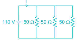
If one of the resistors gest shorted, remaining two resistors also gets shorted as they are connected in parallel. Hence the current flow through each branch will be zero.
Chapter doubts & questions for Electrical Circuits - SSC JE Electrical Mock Test Series 2026 2025 is part of Electrical Engineering (EE) exam preparation. The chapters have been prepared according to the Electrical Engineering (EE) exam syllabus. The Chapter doubts & questions, notes, tests & MCQs are made for Electrical Engineering (EE) 2025 Exam. Find important definitions, questions, notes, meanings, examples, exercises, MCQs and online tests here.
Chapter doubts & questions of Electrical Circuits - SSC JE Electrical Mock Test Series 2026 in English & Hindi are available as part of Electrical Engineering (EE) exam.
Download more important topics, notes, lectures and mock test series for Electrical Engineering (EE) Exam by signing up for free.
SSC JE Electrical Mock Test Series 2026
2 videos|1 docs|55 tests
|
|
© EduRev
|
Education Revolution
|


|


Signup to see your scores
go up
within 7 days!
within 7 days!
Takes less than 10 seconds to signup