


All Exams >
Mechanical Engineering >
Topicwise Question Bank for Mechanical Engineering >
All Questions
All questions of Design of Machine Elements for Mechanical Engineering Exam
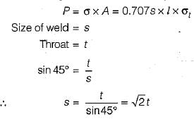
In transverse fillet welded joint, the size of weld is equal to- a) 0.5 x Throat of weld
- b) 0.707 x Throat of weld
- c)
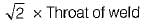
- d)2 x Throat of weld
Correct answer is option 'C'. Can you explain this answer?
In transverse fillet welded joint, the size of weld is equal to
a)
0.5 x Throat of weld
b)
0.707 x Throat of weld
c)
d)
2 x Throat of weld

|
Manish Aggarwal answered |
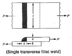
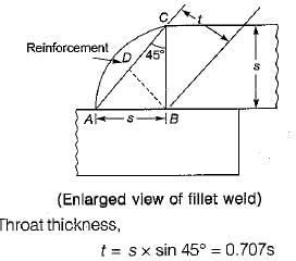
Minimum area of the weld or throat area,
A = Throat thickness x Length of weld
A = 0.707 s x l
Tensile strength,
Tensile strength,

Which one of the following loading is considered for design of axles- a)bending moment only
- b)twisting moment only
- c)combined bending moment and torsion
- d)combined action of bending moment, twisting moment and axial thrust
Correct answer is option 'A'. Can you explain this answer?
Which one of the following loading is considered for design of axles
a)
bending moment only
b)
twisting moment only
c)
combined bending moment and torsion
d)
combined action of bending moment, twisting moment and axial thrust
|
|
Sarita Yadav answered |
Axle is used to support the wheel hence it is subjected to only bending moment. Since it has no role to play in transmission of power hence it is not subjected to twisting moment.
The factor of safety for steel and for steady load is- a)2
- b)4
- c)6
- d)8
Correct answer is option 'B'. Can you explain this answer?
The factor of safety for steel and for steady load is
a)
2
b)
4
c)
6
d)
8
|
|
Divya Banerjee answered |
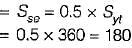
Factor of Safety for Steady Load in Steel
Factor of safety is a measure of the capacity of a material or structure to withstand loads without failure. It is the ratio of the maximum load that a structure can support to the actual load that it is subjected to. The factor of safety for steel and for steady load is 4.
Explanation:
Steady load refers to a constant load that is applied to a structure over a long period of time. For example, the weight of a building or bridge is a steady load. Steel is a commonly used material in construction due to its high strength and durability. The factor of safety for steel is determined by dividing the ultimate strength of the material by the maximum stress that it can endure under normal conditions.
The factor of safety for steel and for steady load is typically set at 4. This means that the maximum load that a structure can support is four times the actual load that it is subjected to. This provides a safety margin to account for unexpected loads or changes in the environment that could affect the structure's stability.
Having a factor of safety of 4 for steel and steady load means that the structure can safely support four times the weight it is designed to hold. This helps to ensure that the structure remains stable and can withstand any unexpected stresses or changes that may arise.
Conclusion:
In conclusion, the factor of safety for steel and for steady load is 4. This provides a safety margin to account for unexpected loads or changes in the environment that could affect the structure's stability. By using steel with a factor of safety of 4, structures can be built to withstand a wide range of loads and remain stable over a long period of time.
Two shafts are connected by means of a flange coupling to transmit torque of 25 N-m. The flanges of the coupling are fastened by four bolts of the same material at a radius of 30 mm. What is the size of bolts if the allowable shear stress for the botl material is 30 MPa?- a)M 4
- b)M 8
- c)M 12
- d)M 16
Correct answer is option 'A'. Can you explain this answer?
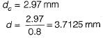
Two shafts are connected by means of a flange coupling to transmit torque of 25 N-m. The flanges of the coupling are fastened by four bolts of the same material at a radius of 30 mm. What is the size of bolts if the allowable shear stress for the botl material is 30 MPa?
a)
M 4
b)
M 8
c)
M 12
d)
M 16
|
|
Sai Reddy answered |
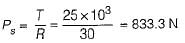
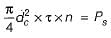
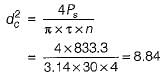
∴
Which of the following ropes will be most flexible?- a)6 x 7
- b)6 x 19
- c)8 x 19
- d)6 x 37
Correct answer is option 'D'. Can you explain this answer?
Which of the following ropes will be most flexible?
a)
6 x 7
b)
6 x 19
c)
8 x 19
d)
6 x 37
|
|
Rhea Reddy answered |
The wire rope of 6 x 7 construction consists of a few wires of relatively large size. It is too stiff for hoisting purposes. The 6 x 19 or 6x 37 constructions are flexible wire ropes, and are commonly used in hoists.
Maximum horse power is transmitted by a belt drive when its velocity is such that the tight side driving tension in belt is equal to- a)centrifugal tension
- b)2 x centrifugal tension
- c)3 x centrifugal tension
- d)4 x centrifugal tension
Correct answer is option 'C'. Can you explain this answer?
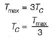
Maximum horse power is transmitted by a belt drive when its velocity is such that the tight side driving tension in belt is equal to
a)
centrifugal tension
b)
2 x centrifugal tension
c)
3 x centrifugal tension
d)
4 x centrifugal tension
|
|
Sarita Yadav answered |
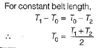
Power transmitted

where
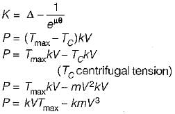 For maximum power to be transmitted
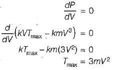
also
Identify the WRONG statement:- a)Shafts and axles support the revolving parts of a machine.
- b)Shafts'and axles are subjected to bending as well as torsional stresses.
- c)A line shaft is a long and continuous shaft used in factories for the distribution of power.
- d). A shaft directly connected to the power source is called jack shaft.
Correct answer is option 'B'. Can you explain this answer?
Identify the WRONG statement:
a)
Shafts and axles support the revolving parts of a machine.
b)
Shafts'and axles are subjected to bending as well as torsional stresses.
c)
A line shaft is a long and continuous shaft used in factories for the distribution of power.
d)
. A shaft directly connected to the power source is called jack shaft.
|
|
Anu Deshpande answered |
Axels do not transmit any torque and are subjected to the effect of bending loads only. A shaft not only supports a revolving part but also transmits torsional moment.
The tooth profiles must not have excessive contact stress as determined by the wear load to insure durability of a gear pair. This wear load is obtained using- a)Barth formula
- b)Buckingham equation
- c)Lewis equation
- d)Hertz equation
Correct answer is option 'B'. Can you explain this answer?
The tooth profiles must not have excessive contact stress as determined by the wear load to insure durability of a gear pair. This wear load is obtained using
a)
Barth formula
b)
Buckingham equation
c)
Lewis equation
d)
Hertz equation
|
|
Neha Joshi answered |
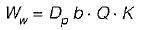
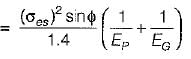
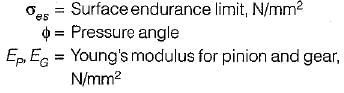
Buckingham equation,
where,
Ww = Maximum or limiting load for wear, N
Dp = PCD, mm
b = face width of the pinion , mm
Q = Ratio Factor
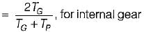
K = Load-stress factor or material combination factor, N/mm2
Dp = PCD, mm
b = face width of the pinion , mm
Q = Ratio Factor
K = Load-stress factor or material combination factor, N/mm2
where,
Which one of the following is criterion in the design of hydrodynamic journal bearings- a)sommerfeld number
- b)rating life
- c)specific dynamic capacity
- d)rotation factor
Correct answer is option 'A'. Can you explain this answer?
Which one of the following is criterion in the design of hydrodynamic journal bearings
a)
sommerfeld number
b)
rating life
c)
specific dynamic capacity
d)
rotation factor

|
Rounak Saini answered |
Sommerfeld number is used in the designing of hydrodynamic bearing while dynamic capacity static capacity is the term used in roiling contact bearing.
For power transmission square threads- a)are least efficient
- b)are less rigid
- c)are expensive to manufacture
- d)wear out very fast
Correct answer is option 'C'. Can you explain this answer?
For power transmission square threads
a)
are least efficient
b)
are less rigid
c)
are expensive to manufacture
d)
wear out very fast
|
|
Dhruv Dasgupta answered |
Square thread:
1. Square threads are less efficient than trapezoidal thread.
2. Square threads are difficult to manufacture. They are usually turned on lathe with single point cutting tool.
3. The strength of a screw depends upon the thread thickness at the core diameter since square thread have less thickness at core than trapezoidal this reduces the load carrying capacity.
Which material is used for bushes in the bushed pin type of flexible coupling- a)Gun metal
- b)Plastic
- c)Rubber
- d)Aluminium
Correct answer is option 'C'. Can you explain this answer?
Which material is used for bushes in the bushed pin type of flexible coupling
a)
Gun metal
b)
Plastic
c)
Rubber
d)
Aluminium
|
|
Sanvi Kapoor answered |
To have some flexibility rubber is used as a material for bushes in bushed pin type flexible coupling.
The dynamic load on a gear is due to:
1. Inaccuracies of tooth spacing.
2. Irregularities in tooth profile.
3. Deflection of the teeth under load.
4. Type of service (i.e., intermittent, one shift per day, continuous per day).
Which of the above statements are correct?- a)1, 2 and 3
- b)2, 3 and 4
- c)1, 3 and 4
- d)1, 2 and 4
Correct answer is option 'A'. Can you explain this answer?
The dynamic load on a gear is due to:
1. Inaccuracies of tooth spacing.
2. Irregularities in tooth profile.
3. Deflection of the teeth under load.
4. Type of service (i.e., intermittent, one shift per day, continuous per day).
Which of the above statements are correct?
1. Inaccuracies of tooth spacing.
2. Irregularities in tooth profile.
3. Deflection of the teeth under load.
4. Type of service (i.e., intermittent, one shift per day, continuous per day).
Which of the above statements are correct?
a)
1, 2 and 3
b)
2, 3 and 4
c)
1, 3 and 4
d)
1, 2 and 4
|
|
Gayatri Dasgupta answered |
The dynamic load between the meshing teeth arises due to following factors:
1. Inaccuracies of tooth profile
2. Error in tooth spacing
3. Runout of gear
4. Gear mesh stiffness variation
5. Inertia of rotating masses
6. Deflection of teeth
7. Stiffness of rotating parts
But dynamic factor mainly depends upon tooth error and pitch line velocity.
1. Inaccuracies of tooth profile
2. Error in tooth spacing
3. Runout of gear
4. Gear mesh stiffness variation
5. Inertia of rotating masses
6. Deflection of teeth
7. Stiffness of rotating parts
But dynamic factor mainly depends upon tooth error and pitch line velocity.
The stress in the bar when load is applied suddenly is Xtimes as compared to the stress induced due to gradually applied load. The value of X is- a)1
- b)2
- c)3
- d)4
Correct answer is option 'B'. Can you explain this answer?
The stress in the bar when load is applied suddenly is Xtimes as compared to the stress induced due to gradually applied load. The value of X is
a)
1
b)
2
c)
3
d)
4
|
|
Saikat Choudhary answered |
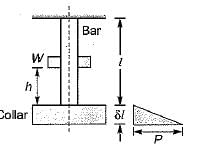
The energy gained by the system in the form of strain energy

The potential energy lost by the weight
The objective of caulking in a riveted joint is to make the joint- a)Leakproof
- b)Stronger
- c)Less stressed
- d)None of these
Correct answer is option 'A'. Can you explain this answer?
The objective of caulking in a riveted joint is to make the joint
a)
Leakproof
b)
Stronger
c)
Less stressed
d)
None of these
|
|
Samarth Chaudhary answered |
Caulking is used to make the riveted joint leak proof or fluid tight in pressure vessel like steam boilers, air receivers and tank etc.
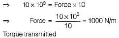
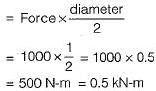
A spur gear transmits 10 kW at a pitch line velocity of 10 m/s; driving gear has a diameter of 1.0 m. Find the tangential force between the driver and the follower, and the transmitted torque respectively.- a)1 kN and 0.5 kN-m
- b)10 kN and 5 kN-m
- c)0.5 kN and 0.25 kN-m
- d)1 kN and 1 kN-m
Correct answer is option 'A'. Can you explain this answer?
A spur gear transmits 10 kW at a pitch line velocity of 10 m/s; driving gear has a diameter of 1.0 m. Find the tangential force between the driver and the follower, and the transmitted torque respectively.
a)
1 kN and 0.5 kN-m
b)
10 kN and 5 kN-m
c)
0.5 kN and 0.25 kN-m
d)
1 kN and 1 kN-m

|
Samridhi Choudhary answered |
Power transmitted = Force x Velocity
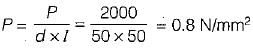
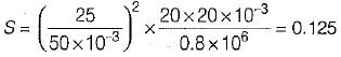
A natural feed journal bearing of diameter 50 mm and length 50 mm operating at 20 revolution/sec. carries a load of 2.0 kN. The lubricant used has a viscosity of 20 MPa/s. The radial clearance is 50 μm. The Sommerfield number for the bearings is- a)0.062
- b)0.125
- c)0.250
- d)0.785
Correct answer is option 'B'. Can you explain this answer?
A natural feed journal bearing of diameter 50 mm and length 50 mm operating at 20 revolution/sec. carries a load of 2.0 kN. The lubricant used has a viscosity of 20 MPa/s. The radial clearance is 50 μm. The Sommerfield number for the bearings is
a)
0.062
b)
0.125
c)
0.250
d)
0.785
|
|
Anuj Verma answered |
Sommerfield number
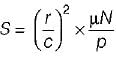
Where, r is radius of journal
μ is viscosity of lubricant
N is number of revolution per second
ρ is bearing pressure on projected Area
C is radial clearance
Therefore,
Where, r is radius of journal
μ is viscosity of lubricant
N is number of revolution per second
ρ is bearing pressure on projected Area
C is radial clearance
Therefore,
In hydrodynamic bearings- a)the oil film pressure is generated only by the rotation of the journal
- b)the oil film is maintained by supplying-oil under pressure
- c)no oil film is required in hydrodynamic bearings
- d)none of these
Correct answer is option 'A'. Can you explain this answer?
In hydrodynamic bearings
a)
the oil film pressure is generated only by the rotation of the journal
b)
the oil film is maintained by supplying-oil under pressure
c)
no oil film is required in hydrodynamic bearings
d)
none of these
|
|
Nandini Basak answered |
Hydrodynamic bearing is a thick film lubrication bearing in which oil pressure is generated due to rotation of shaft.
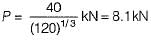
A bearing has a specific dynamic radial capacity of 40 kN. What equivalent radial load P can the bearing carry at 400 rpm, if the desired life H is 5000 hours for 90% of the bearings?- a)8.11 kN
- b)6 kN
- c)6.8 kN
- d)9.11 kN
Correct answer is option 'A'. Can you explain this answer?
A bearing has a specific dynamic radial capacity of 40 kN. What equivalent radial load P can the bearing carry at 400 rpm, if the desired life H is 5000 hours for 90% of the bearings?
a)
8.11 kN
b)
6 kN
c)
6.8 kN
d)
9.11 kN
|
|
Nitin Joshi answered |
Life in revolutions = (5000 x 60) min x 400 rev/ min = 120 x 106 rev
Life in millions of revoutions = (C/P)3
Life in millions of revoutions = (C/P)3

A thin cylindrical tube closed at ends is subjected to internal pressure. A torque is also applied to the tube. The principal stresses p1 and p2 developed are 80 unit and 20 unit respectively. If the yield stress is 240 units then what is the factor of safety according to maximum shear stress theory- a)3
- b)4
- c)5
- d)2
Correct answer is option 'B'. Can you explain this answer?
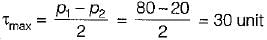
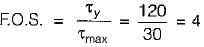
A thin cylindrical tube closed at ends is subjected to internal pressure. A torque is also applied to the tube. The principal stresses p1 and p2 developed are 80 unit and 20 unit respectively. If the yield stress is 240 units then what is the factor of safety according to maximum shear stress theory
a)
3
b)
4
c)
5
d)
2
|
|
Sparsh Chakraborty answered |
Maximum shear stress due to applied loading
Maximum shear stress in material at yield stress under uni-axial tension
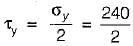
= 120 unit
Maximum shear stress in material at yield stress under uni-axial tension
= 120 unit
A journal 30 mm in diameter supported in sliding bearings has a maximum end reaction of 2500 N. What is the length of sliding bearing for an allowable bearing pressure of 5 N/mm2?- a)12 mm
- b)14.67 mm
- c)16.67 mm
- d)19 mm
Correct answer is option 'C'. Can you explain this answer?
A journal 30 mm in diameter supported in sliding bearings has a maximum end reaction of 2500 N. What is the length of sliding bearing for an allowable bearing pressure of 5 N/mm2?
a)
12 mm
b)
14.67 mm
c)
16.67 mm
d)
19 mm
|
|
Prateek Mukherjee answered |
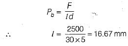
Projected area,
A = l x d =30 l mm2
Bearing pressure,
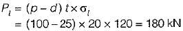
A double riveted double cover butt joint in plates 20 mm thick is made with 25 mm diameter rivets at 100 mm pitch. The permissible stresses are σt = 120 MPa, τ = 100 MPa, σc= 150 MPa. Taking the strength of the rivet in double shear as twice that of single shear, the tearing resistance of the plate is- a)120 kN
- b)140kN
- c)160 kN
- d)180 kN
Correct answer is option 'D'. Can you explain this answer?
A double riveted double cover butt joint in plates 20 mm thick is made with 25 mm diameter rivets at 100 mm pitch. The permissible stresses are σt = 120 MPa, τ = 100 MPa, σc= 150 MPa. Taking the strength of the rivet in double shear as twice that of single shear, the tearing resistance of the plate is
a)
120 kN
b)
140kN
c)
160 kN
d)
180 kN
|
|
Nitin Joshi answered |
A hydraulic press exerts a total load of 4 MN. This load' is carried by two steel rods, supporting the upper head of the press. If the safe stress is 100 MPa and E =210 kN/mm2, what is the design diameter of supporting steel rods?- a) 160 mm
- b)165 mm
- c)170 mm
- d)175 mm
Correct answer is option 'A'. Can you explain this answer?
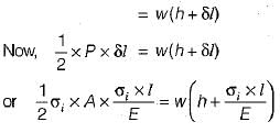
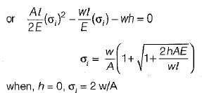
A hydraulic press exerts a total load of 4 MN. This load' is carried by two steel rods, supporting the upper head of the press. If the safe stress is 100 MPa and E =210 kN/mm2, what is the design diameter of supporting steel rods?
a)
160 mm
b)
165 mm
c)
170 mm
d)
175 mm
|
|
Rajat Patel answered |
Given data:
Total load carried by the steel rods = 4 MN
Safe stress = 100 MPa
Elastic modulus of steel (E) = 210 kN/mm2
To find: Design diameter of supporting steel rods
We can use the following formula to calculate the stress:
Stress = Load/Area
Let's assume the diameter of each rod as 'd' and the cross-sectional area as 'A'.
The load carried by each rod can be calculated as half of the total load, since there are two rods.
Load carried by each rod = Total load/2 = 4 MN/2 = 2 MN
We can rearrange the formula to find the area:
Area = Load/Stress
Substituting the values, we get:
A = (2 MN)/(100 MPa) = (2 × 10⁶ N)/(100 × 106 N/m2) = 20 × 10-3 m2
The area of a circle is given by the formula:
A = πd2/4
Rearranging the formula, we can find the diameter:
d = √(4A/π)
Substituting the value of area, we get:
d = √(4 × 20 × 10-3/π) = √(80 × 10-3/π) = √(80/π) × 10-3 ≈ 160 mm
Therefore, the design diameter of the supporting steel rods is approximately 160 mm.
Hence, option A (160 mm) is the correct answer.
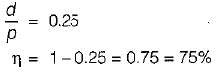
If P is the pitch of a square thread, then the depth of thread d is given by- a)0.5 P
- b)P
- c)1.5 P
- d)2 P
Correct answer is option 'A'. Can you explain this answer?
If P is the pitch of a square thread, then the depth of thread d is given by
a)
0.5 P
b)
P
c)
1.5 P
d)
2 P
|
|
Atharva Majumdar answered |
The correct answer to the given question is option 'A', which states that the depth of thread (d) is equal to 0.5 times the pitch (P) of a square thread.
A square thread is a type of screw thread that has a square cross-section. It is commonly used in applications where a large amount of linear force is required, such as in vices, clamps, and jacks. The pitch of a square thread refers to the distance between adjacent threads, measured along the axis of the screw.
To understand why the depth of thread is half the pitch, let's break down the components of a square thread:
1. Pitch (P): The pitch is the distance between two adjacent threads. It is typically measured in millimeters or inches.
2. Depth of thread (d): The depth of thread is the distance from the crest (top) of the thread to the root (bottom) of the thread. It determines the engagement between the male and female threads.
Now, let's consider the geometry of a square thread:
- A square thread has equal height and width, resulting in a square-shaped cross-section.
- The depth of thread (d) is equal to the difference in height between the crest and root of the thread.
Based on the geometry of a square thread, we can deduce that the depth of thread is half the pitch:
- When a square thread is fully engaged, the crest of one thread is in contact with the root of the adjacent thread.
- This means that the depth of thread is equal to half the pitch, as the crest and root of adjacent threads align.
Therefore, the correct answer is option 'A', which states that the depth of thread (d) is equal to 0.5 times the pitch (P) of a square thread.
For bolts of uniform strength, the shank diameter is made equal to- a)major diameter of threads
- b)pitch diameter of threads
- c)minor diameter of threads
- d)nominal diameter of threads
Correct answer is option 'C'. Can you explain this answer?
For bolts of uniform strength, the shank diameter is made equal to
a)
major diameter of threads
b)
pitch diameter of threads
c)
minor diameter of threads
d)
nominal diameter of threads
|
|
Stuti Mishra answered |
Bolt of uniform strength are made by
1. Reducing the diameter of shank of bolt corresponding to that of minor diameter.
2. Making a hole and making the area of shank equal to root area.
1. Reducing the diameter of shank of bolt corresponding to that of minor diameter.
2. Making a hole and making the area of shank equal to root area.
Select the wrong statement:- a)The uniform pressure theory is applicable only when the friction lining is new.
- b)The uniform wear theory is applicable when the friction lining gets worn out.
- c)The friction radius for new clutches is slightly greater than that of worn-out clutches.
- d)A major portion of the life of friction lining comes under uniform pressure criterion.
Correct answer is option 'D'. Can you explain this answer?
Select the wrong statement:
a)
The uniform pressure theory is applicable only when the friction lining is new.
b)
The uniform wear theory is applicable when the friction lining gets worn out.
c)
The friction radius for new clutches is slightly greater than that of worn-out clutches.
d)
A major portion of the life of friction lining comes under uniform pressure criterion.
|
|
Dishani Desai answered |
A major portion of the life of friction lining comes under uniform wear criterion.
Allowable tooth stress for gear-tooth design depends upon the following parameters:
1. Type of gear material
2. Pitch line velocity
3. Beam strength of gear teeth Which of the above is/are valid?- a)1 only
- b)3 only
- c)1 and 3
- d)2 and 3
Correct answer is option 'C'. Can you explain this answer?
Allowable tooth stress for gear-tooth design depends upon the following parameters:
1. Type of gear material
2. Pitch line velocity
3. Beam strength of gear teeth
1. Type of gear material
2. Pitch line velocity
3. Beam strength of gear teeth
Which of the above is/are valid?
a)
1 only
b)
3 only
c)
1 and 3
d)
2 and 3
|
|
Pallabi Tiwari answered |
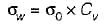
Allowable stress,
where,
σ0 is the endurance strength of material
Cv is the velocity factor
Cv is the velocity factor
The ratio of inner to outer radii of a clutch is normally taken between- a)0.3 - 0.4
- b)0.4 - 0.5
- c)0.5 - 0.6
- d)0.6 - 0.7
Correct answer is option 'D'. Can you explain this answer?
The ratio of inner to outer radii of a clutch is normally taken between
a)
0.3 - 0.4
b)
0.4 - 0.5
c)
0.5 - 0.6
d)
0.6 - 0.7
|
|
Dhruv Dasgupta answered |
If equal importance is given to durability and torsional moment output, (r1/r2) is taken as 0.48. In practice, (r1/r2) is usually kept between 0.6 and 0.7.
Consider the following parameter:
1. Oil pressure
2. Bearing metal temperature
3. Drain oil temperature
4. Bearing vibration
5. Friction coefficienWhich of the above should be monitored for determining safe operation of journal bearing?- a)1,2 and 3
- b)1,2, 3 and 4
- c)1, 2, 3 and 5
- d)All of the above
Correct answer is option 'B'. Can you explain this answer?
Consider the following parameter:
1. Oil pressure
2. Bearing metal temperature
3. Drain oil temperature
4. Bearing vibration
5. Friction coefficien
1. Oil pressure
2. Bearing metal temperature
3. Drain oil temperature
4. Bearing vibration
5. Friction coefficien
Which of the above should be monitored for determining safe operation of journal bearing?
a)
1,2 and 3
b)
1,2, 3 and 4
c)
1, 2, 3 and 5
d)
All of the above
|
|
Nayanika Yadav answered |
Parameters to monitor for determining safe operation of journal bearing:
1. Oil pressure:
- Low oil pressure can result in inadequate lubrication which can cause excessive wear and tear of bearing surfaces.
- High oil pressure can cause excessive heat generation and damage to the bearing surfaces.
2. Bearing metal temperature:
- Elevated bearing temperature can indicate insufficient lubrication, excessive loading or misalignment.
- Too low bearing temperature can lead to inadequate lubrication and increased friction.
3. Drain oil temperature:
- Indicates the temperature of the oil leaving the bearing.
- High temperature can indicate excessive heat generation in the bearing and insufficient cooling.
- Low temperature can indicate insufficient lubrication.
4. Bearing vibration:
- Excessive bearing vibration can lead to fatigue failure and damage to the bearing.
- Can be caused by misalignment, imbalance, or inadequate lubrication.
5. Friction coefficient:
- Indicates the amount of friction between the bearing surfaces.
- High friction coefficient can cause excessive wear and tear on the bearing surfaces and lead to bearing failure.
Conclusion:
All the above parameters should be monitored to determine safe operation of journal bearings. Specifically, oil pressure, bearing metal temperature, drain oil temperature and bearing vibration are critical parameters that can indicate potential problems with the bearing.
The most suitable bearing for carrying very heavy loads with slow speed is- a)hydrodynamic bearing
- b)ball bearing
- c)roller bearing
- d)hydrostatic bearing
Correct answer is option 'D'. Can you explain this answer?
The most suitable bearing for carrying very heavy loads with slow speed is
a)
hydrodynamic bearing
b)
ball bearing
c)
roller bearing
d)
hydrostatic bearing
|
|
Divyansh Goyal answered |
The hydrostatic bearings are those which can support steady loads without any relative motion between the journal and the bearings. This condition is achieved by forcing externally pressurized lubricant bewteen the members.
Match List-I (Application) with List-ll (Joint) and select the correct answer using the code given below the lists:
List-I
A. Boiler Shell
B. Marine Shaft Coupling
C. Crosshead and Piston Rod
D. Automobile gear box (gears to shaft)
List-II
1. Cotter Joint
2. Knuckle Joi
3. Riveted join
4. Splines
5. Bolted Joint
Codes:
A B C D
(a) 1 4 2 5
(b) 3 5 1 4
(c) 1 5 2 4
(d) 3 4 1 5- a)(a)
- b)(b)
- c)(c)
- d)(d)
Correct answer is option 'B'. Can you explain this answer?
Match List-I (Application) with List-ll (Joint) and select the correct answer using the code given below the lists:
List-I
A. Boiler Shell
B. Marine Shaft Coupling
C. Crosshead and Piston Rod
D. Automobile gear box (gears to shaft)
List-II
1. Cotter Joint
2. Knuckle Joi
3. Riveted join
4. Splines
5. Bolted Joint
Codes:
A B C D
(a) 1 4 2 5
(b) 3 5 1 4
(c) 1 5 2 4
(d) 3 4 1 5
List-I
A. Boiler Shell
B. Marine Shaft Coupling
C. Crosshead and Piston Rod
D. Automobile gear box (gears to shaft)
List-II
1. Cotter Joint
2. Knuckle Joi
3. Riveted join
4. Splines
5. Bolted Joint
Codes:
A B C D
(a) 1 4 2 5
(b) 3 5 1 4
(c) 1 5 2 4
(d) 3 4 1 5
a)
(a)
b)
(b)
c)
(c)
d)
(d)
|
|
Ashutosh Sharma answered |
(A) Boiler shell → Riveted joint
(B) Marine shaft coupling → Bolted joint
(C) Crosshead and piston rod → Cotter joint
(D) Automobile gear box → Splines
(B) Marine shaft coupling → Bolted joint
(C) Crosshead and piston rod → Cotter joint
(D) Automobile gear box → Splines
To ensure self-locking in a screw jack it is essential that helix angle is- a)larger than friction angle
- b)smaller than friction angle
- c)equal to friction angle
- d)such as to give maximum efficiency in lifting
Correct answer is option 'B'. Can you explain this answer?
To ensure self-locking in a screw jack it is essential that helix angle is
a)
larger than friction angle
b)
smaller than friction angle
c)
equal to friction angle
d)
such as to give maximum efficiency in lifting
|
|
Sagarika Mukherjee answered |
Explanation:
Friction Angle:
- The friction angle is the angle at which two surfaces meet and resist relative motion.
- In the case of a screw jack, the friction angle represents the resistance to motion between the threads of the screw and the load being lifted.
Helix Angle:
- The helix angle of a screw jack is the angle between the thread helix and the axis of the screw.
- It determines the efficiency and self-locking ability of the screw jack.
Relationship between Helix Angle and Friction Angle:
- In order to ensure self-locking in a screw jack, the helix angle must be smaller than the friction angle.
- A smaller helix angle creates a steeper thread profile, which increases the resistance to motion and prevents the screw jack from self-lowering under load.
- If the helix angle is larger than the friction angle, the screw jack may not be able to hold the load in place and could start to unwind.
Conclusion:
- Therefore, to ensure self-locking in a screw jack, the helix angle must be smaller than the friction angle to provide sufficient resistance and prevent the screw jack from self-lowering.
The relationship between diameter of rivet hole and plate thickness (Unwin formula) is given by
- a)d = 6√t
- b)d = 1.5t
- c)d = 6t
- d)d = 2t
Correct answer is option 'A'. Can you explain this answer?
The relationship between diameter of rivet hole and plate thickness (Unwin formula) is given by
a)
d = 6√t
b)
d = 1.5t
c)
d = 6t
d)
d = 2t
|
|
Pallabi Bajaj answered |
The relation between diameter of rivet hole and plate thickness is given by unwin as
d = 6√t
where, d = diameter of rivet hole plate thickness
d = 6√t
where, d = diameter of rivet hole plate thickness
A disc clutch is required to transmit 5 kW at 2000 rpm. The disc has a friction lining with coefficient of friction equal to 0.25. Bore radius of friction lining is equal 0.25 mm. Assume uniform contact pressure of 1 MPa. The value of outside radius of the friction lining is- a)39.4 mm
- b)49.5 mm
- c)97.9 mm
- d)142.9 mm
Correct answer is option 'A'. Can you explain this answer?
A disc clutch is required to transmit 5 kW at 2000 rpm. The disc has a friction lining with coefficient of friction equal to 0.25. Bore radius of friction lining is equal 0.25 mm. Assume uniform contact pressure of 1 MPa. The value of outside radius of the friction lining is
a)
39.4 mm
b)
49.5 mm
c)
97.9 mm
d)
142.9 mm
|
|
Poulomi Patel answered |
Power Transmitted = 5 kW
N = 2000 rpm
μ = 0.25
r1 = 25 mm
Uniform Pressure = 1 MPa
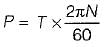
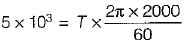
T = 23.87 N-m
Pressure
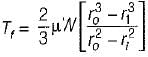
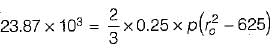

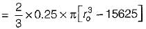
ro= 39.4 mm
Bolts in a rigid flangecoupling fails in shear and crushing.
N = 2000 rpm
μ = 0.25
r1 = 25 mm
Uniform Pressure = 1 MPa
T = 23.87 N-m
Pressure
ro= 39.4 mm
Bolts in a rigid flangecoupling fails in shear and crushing.
Stress concentration factor is ratio of- a)endurance limit without stress concentration to endurance limit with stress concentration
- b)endurance limit with stress concentration to endurance limit without stress concentration
- c)endurance limit with stress concentration to factor of safety
- d)none of these
Correct answer is option 'A'. Can you explain this answer?
Stress concentration factor is ratio of
a)
endurance limit without stress concentration to endurance limit with stress concentration
b)
endurance limit with stress concentration to endurance limit without stress concentration
c)
endurance limit with stress concentration to factor of safety
d)
none of these
|
|
Sai Sarkar answered |
Fatigue stress concentration factor can be defined as the ratio of endurance limit without stress concentration to the endurance limit with stress concetration.
Bearing used for heavy loads are- a)ball bearings
- b)roller bearings
- c)thrust bearings
- d)any of the above
Correct answer is option 'B'. Can you explain this answer?
Bearing used for heavy loads are
a)
ball bearings
b)
roller bearings
c)
thrust bearings
d)
any of the above
|
|
Dipika Nambiar answered |
Roller Bearings for Heavy Loads
Roller bearings are commonly used for heavy loads due to their ability to distribute weight over a larger surface area compared to ball bearings. This results in reduced friction and increased load-bearing capacity.
Types of Roller Bearings:
- Cylindrical roller bearings: These are suitable for high radial loads and moderate thrust loads.
- Tapered roller bearings: Designed to handle both radial and axial loads, commonly used in automotive applications.
- Spherical roller bearings: Can accommodate misalignment and heavy radial loads.
- Needle roller bearings: Ideal for applications with limited space and high load requirements.
Advantages of Roller Bearings:
- Higher load capacity: Roller bearings can support heavier loads compared to ball bearings.
- Durability: Roller bearings have a longer lifespan due to reduced wear and friction.
- Reduced heat generation: The larger contact area in roller bearings helps dissipate heat more effectively.
Applications of Roller Bearings:
- Heavy machinery: Used in construction equipment, mining machinery, and agricultural machinery.
- Automotive industry: Found in wheel bearings, transmissions, and engine components.
- Industrial applications: Utilized in conveyor systems, gearboxes, and pumps.
In conclusion, roller bearings are the preferred choice for applications involving heavy loads due to their superior load-bearing capacity, durability, and reduced heat generation.
Select the WRONG statement:- a)Stress concentration in static load is more pronounced in case of brittle materials.
- b)In cyclic loading, stress concentration is more serious in ductile materials.
- c)The maximum stress at the location of stress concentration is determined by photographic method.
- d)Stress concentration factor is independent of the geometry of discontinues in configuration of the machine part.
Correct answer is option 'B'. Can you explain this answer?
Select the WRONG statement:
a)
Stress concentration in static load is more pronounced in case of brittle materials.
b)
In cyclic loading, stress concentration is more serious in ductile materials.
c)
The maximum stress at the location of stress concentration is determined by photographic method.
d)
Stress concentration factor is independent of the geometry of discontinues in configuration of the machine part.
|
|
Devansh Sengupta answered |
The effect of stress concentration is more severe in case of brittle materials, due to their inability of plastic deformation. Brittle materials do not yield locally and there is no readjustment of stresses at the discontinuities.
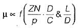
It is seen from the curve that there is a minimum value of the coefficient of friction (m) for a particular value of the Bearing Characterstic Number denoted by a. What is this value of the Bearing Characteristic Number called?- a)McKee Number
- b)Reynolds Number
- c)Bearing Modulus
- d)Sommerfeld Number
Correct answer is option 'C'. Can you explain this answer?
It is seen from the curve that there is a minimum value of the coefficient of friction (m) for a particular value of the Bearing Characterstic Number denoted by a. What is this value of the Bearing Characteristic Number called?
a)
McKee Number
b)
Reynolds Number
c)
Bearing Modulus
d)
Sommerfeld Number

|
Sneha Nair answered |
Bearing Characteristic Number (BCN) is a dimensionless parameter used in the study of fluid film bearings. It is defined as the ratio of the load-carrying capacity of the bearing to the viscous resistance of the lubricant. The BCN is a measure of the effectiveness of the bearing in supporting the load and reducing friction.
The curve mentioned in the question represents the relationship between the coefficient of friction (m) and the BCN. The coefficient of friction is a measure of the resistance to relative motion between two surfaces in contact. In the case of a bearing, it represents the frictional resistance between the rotating shaft and the bearing surface.
The curve shows that there is a minimum value of the coefficient of friction for a particular value of the BCN. This means that at this specific BCN value, the bearing is operating at its optimal condition, with minimum friction and maximum load-carrying capacity.
The correct term for this specific BCN value is the Bearing Modulus. The Bearing Modulus is a measure of the stiffness of the bearing and is defined as the BCN at the point of minimum coefficient of friction. It represents the ability of the bearing to support the load without excessive deformation or deflection.
The Bearing Modulus is an important parameter in bearing design and selection. It helps engineers determine the appropriate bearing size and type for a given application, considering factors such as load, speed, and operating conditions. By operating the bearing at its Bearing Modulus, the friction and wear can be minimized, leading to improved performance and longevity of the bearing.
In summary, the value of the Bearing Characteristic Number at the point of minimum coefficient of friction is called the Bearing Modulus. It represents the optimal operating condition of the bearing, where the load-carrying capacity is maximized and the friction is minimized.
A cold rolled steel shaft is designed on the basis of maximum shear stress theory. The principal stresses induced at its critical section are 60 MPa and -60 MPa respectively. If the yield stress for the shaft material is 360 MPa, the factor of safety of the design is:- a)2
- b)3
- c)4
- d)6
Correct answer is option 'B'. Can you explain this answer?
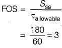
A cold rolled steel shaft is designed on the basis of maximum shear stress theory. The principal stresses induced at its critical section are 60 MPa and -60 MPa respectively. If the yield stress for the shaft material is 360 MPa, the factor of safety of the design is:
a)
2
b)
3
c)
4
d)
6
|
|
Saikat Choudhary answered |
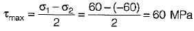
According to maximum shear stress theory
Yield stress in shear

In case of belt drives, the effect of the centrifugal tension is to- a)cause the belt to leave the pulley and increases the power to be transmitted
- b)cause the belt to stay on the pulley and increase the power to be transmitted
- c)reduce the driving power of the belt
- d)stretch the belt in longitudinal direction
Correct answer is option 'C'. Can you explain this answer?
In case of belt drives, the effect of the centrifugal tension is to
a)
cause the belt to leave the pulley and increases the power to be transmitted
b)
cause the belt to stay on the pulley and increase the power to be transmitted
c)
reduce the driving power of the belt
d)
stretch the belt in longitudinal direction
|
|
Anjali Shah answered |
Effect of Centrifugal Tension in Belt Drives
Centrifugal tension is the tension that is produced in a belt drive due to the flinging action of the belt as it rotates. This tension is dependent on the speed of rotation of the pulleys and the mass of the belt.
The effect of centrifugal tension on a belt drive is as follows:
Reduction in Driving Power
When the speed of rotation of the pulleys increases, the centrifugal tension also increases. This tension acts in the outward direction and opposes the tension that is applied to the belt by the pulleys. As a result, the effective tension in the belt reduces, leading to a reduction in the driving power of the belt.
Loss of Contact between Belt and Pulley
If the centrifugal tension becomes greater than the tension that is applied to the belt by the pulleys, the belt may lose contact with the pulleys. This can result in a loss of power transmission as the belt is no longer able to transmit the torque from the driving pulley to the driven pulley.
Conclusion
In summary, the effect of centrifugal tension in a belt drive is to reduce the driving power of the belt and, in extreme cases, to cause the belt to lose contact with the pulleys. Therefore, it is important to consider the effect of centrifugal tension when designing belt drives and to ensure that the belt is properly tensioned to prevent loss of power transmission.
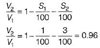
In flat belt drive, if the slip between the driver and the belt is 1%, that between belt and follower is 3% and driver and flower pulley diameters are equal, then the velocity ratio of the drive will be:- a)0.99
- b)0.98
- c)0.97
- d)0.96
Correct answer is option 'D'. Can you explain this answer?
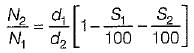
In flat belt drive, if the slip between the driver and the belt is 1%, that between belt and follower is 3% and driver and flower pulley diameters are equal, then the velocity ratio of the drive will be:
a)
0.99
b)
0.98
c)
0.97
d)
0.96
|
|
Dipanjan Ghosh answered |
Consider the following statements:
For a journal rotating in a bearing under film lubrication conditions, the frictional resistance is
1. Proportional to the area of contact
2. Proportional to the viscosity of lubricant
3. Proportional to the speed of rotation
4. Independent of the pressure
Q. Which of the statements given above are correct?- a)1, 2, 3 and 4
- b)1 and 4 only
- c)2, 3 and 4 only
- d)2 and 3 only
Correct answer is option 'D'. Can you explain this answer?
Consider the following statements:
For a journal rotating in a bearing under film lubrication conditions, the frictional resistance is
1. Proportional to the area of contact
2. Proportional to the viscosity of lubricant
3. Proportional to the speed of rotation
4. Independent of the pressure
Q. Which of the statements given above are correct?
a)
1, 2, 3 and 4
b)
1 and 4 only
c)
2, 3 and 4 only
d)
2 and 3 only
|
|
Stuti Bajaj answered |
Frictional resistance ∝ Z
∝ N
∝ 1/p
So 2 or 3 is correct.
A silent chain consists of- a)links and blocks
- b)links, pins, bushings and rollers
- c)inverted tooth over-lapping links
- d)oval links
Correct answer is option 'C'. Can you explain this answer?
A silent chain consists of
a)
links and blocks
b)
links, pins, bushings and rollers
c)
inverted tooth over-lapping links
d)
oval links
|
|
Avinash Sharma answered |
A silent chain is also known as inverted tooth chain. It is designed to eliminate the evil effects caused by stretching and to produce noiseless running.
What diameter should the driving pulley have on which a rubber belt runs so that bending stress in belt is limited to 5 N/mm2 (the belt cross-section is a rectangle 15 mm thick x 110 mm wide, E for belt material is 100 N/mm2)- a)30 mm
- b)150 mm
- c)300 mm
- d)15 mm
Correct answer is option 'C'. Can you explain this answer?
What diameter should the driving pulley have on which a rubber belt runs so that bending stress in belt is limited to 5 N/mm2 (the belt cross-section is a rectangle 15 mm thick x 110 mm wide, E for belt material is 100 N/mm2)
a)
30 mm
b)
150 mm
c)
300 mm
d)
15 mm
|
|
Sanaya Sengupta answered |

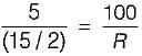
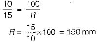
D = 300 mm
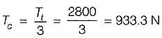
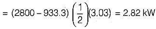
A belt having dimension 20 cm x 1 cm has the ratio of tension 2 and maximum permissible tension is 140 N/cm2. Weight density of leather is 1000 N/m2. The maximum power that can be transmitted is- a)2.828 kW
- b)1.828 kW
- c)2.228 kW
- d)3.228 kW
Correct answer is option 'A'. Can you explain this answer?
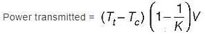
A belt having dimension 20 cm x 1 cm has the ratio of tension 2 and maximum permissible tension is 140 N/cm2. Weight density of leather is 1000 N/m2. The maximum power that can be transmitted is
a)
2.828 kW
b)
1.828 kW
c)
2.228 kW
d)
3.228 kW
|
|
Jithin Choudhury answered |

T1 = 140 x 20 = 2800 N
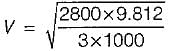
= 3.03 M/sec
Chapter doubts & questions for Design of Machine Elements - Topicwise Question Bank for Mechanical Engineering 2025 is part of Mechanical Engineering exam preparation. The chapters have been prepared according to the Mechanical Engineering exam syllabus. The Chapter doubts & questions, notes, tests & MCQs are made for Mechanical Engineering 2025 Exam. Find important definitions, questions, notes, meanings, examples, exercises, MCQs and online tests here.
Chapter doubts & questions of Design of Machine Elements - Topicwise Question Bank for Mechanical Engineering in English & Hindi are available as part of Mechanical Engineering exam.
Download more important topics, notes, lectures and mock test series for Mechanical Engineering Exam by signing up for free.
Topicwise Question Bank for Mechanical Engineering
45 videos|314 tests
|
|
© EduRev
|
Education Revolution
|


|


Signup to see your scores
go up
within 7 days!
within 7 days!
Takes less than 10 seconds to signup