


All Exams >
Electrical Engineering (EE) >
Topicwise Question Bank for Electrical Engineering >
All Questions
All questions of Power Systems for Electrical Engineering (EE) Exam
Unit of heat rate curve is- a)Rs-hr
- b)Rs/MWh
- c)Rs/hr
- d)Million kcal/hr
Correct answer is option 'D'. Can you explain this answer?
Unit of heat rate curve is
a)
Rs-hr
b)
Rs/MWh
c)
Rs/hr
d)
Million kcal/hr
|
|
Samarth Khanna answered |
Unit of Heat Rate Curve is Million kcal/hr because it represents the rate at which heat is being generated or consumed in a power plant. The heat rate is a measure of the thermal efficiency of a power plant and is usually expressed in units of energy per unit of time.
- Heat Rate Curve:
The heat rate curve is a graphical representation of the relationship between the heat input to a power plant and the power output. It shows how the heat rate varies with the power output of the plant. The heat rate curve is typically plotted with heat rate on the y-axis and power output on the x-axis.
- Importance of Heat Rate:
The heat rate of a power plant is an important parameter as it indicates how efficiently the plant converts fuel into electricity. A lower heat rate means that the plant is more efficient and requires less fuel to generate a given amount of electricity. On the other hand, a higher heat rate indicates that the plant is less efficient and requires more fuel for the same power output.
- Million kcal/hr:
The unit of heat rate in the heat rate curve is Million kcal/hr. This unit represents the amount of heat energy generated or consumed by the power plant in one hour. It is a large unit of energy and is commonly used in the power generation industry.
- Conversion to Other Units:
The heat rate can also be expressed in other units such as BTU/kWh or MMBtu/MWh. These units represent the amount of heat energy required to generate one kilowatt-hour or one megawatt-hour of electricity, respectively. However, the unit of Million kcal/hr is widely used in the industry and is convenient for comparing the performance of different power plants.
- Conclusion:
In conclusion, the unit of heat rate curve is Million kcal/hr. This unit represents the rate at which heat energy is being generated or consumed by a power plant. The heat rate curve is an important tool for assessing the efficiency of a power plant and comparing the performance of different plants.

In which part of the thermal power plant, the steam pressure is less than that of atmosphere?- a)Boiler
- b)Turbine
- c)Superheater
- d)Condenser
Correct answer is option 'D'. Can you explain this answer?
In which part of the thermal power plant, the steam pressure is less than that of atmosphere?
a)
Boiler
b)
Turbine
c)
Superheater
d)
Condenser
|
|
Zoya Sharma answered |
Condenser in a steam power plant has lowest operating pressure.
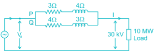
Two overhead Lines ‘P’ and ‘Q’ are connected in parallel to supply a load of 10 MW at 0.8 pf lagging. The resistance and reactance of line ‘P’ are 3 Ω and 4 Ω, respectively and of the Line, ‘Q’ is 4 Ω and 3 Ω respectively. The power supplied by the ‘P’ is- a)6.30 MW
- b)4.46 MW
- c)6.73 MW
- d)5.88 MW
Correct answer is option 'B'. Can you explain this answer?
Two overhead Lines ‘P’ and ‘Q’ are connected in parallel to supply a load of 10 MW at 0.8 pf lagging. The resistance and reactance of line ‘P’ are 3 Ω and 4 Ω, respectively and of the Line, ‘Q’ is 4 Ω and 3 Ω respectively. The power supplied by the ‘P’ is
a)
6.30 MW
b)
4.46 MW
c)
6.73 MW
d)
5.88 MW
|
|
Prasad Verma answered |
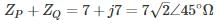
Impedance of Line P, ZP = 3 + j4 = 5∠53.13° Ω
Impedance of Line Q, ZQ = 4 + j3 = 5∠36.86° Ω
Total load supplied in kVA
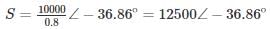
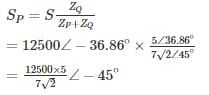
Load supplied by Line P
Total load supplied in kVA
Load supplied by Line P
= 6313.45 kVA at pf 0.708
Power supplied by Line P,
P = 6313.45 × 0.707 = 4.46 MW
Which is the conventional source of energy?- a)Solar
- b)Radio-active substances
- c)Geothermal
- d)Wind
Correct answer is option 'B'. Can you explain this answer?
Which is the conventional source of energy?
a)
Solar
b)
Radio-active substances
c)
Geothermal
d)
Wind
|
|
Juhi Joshi answered |
Conventional source of energy are: Water, Coal, Gas, radioactive substances. Non-conventional source of energy are: Wind, Solar energy, Geothermal.
Series capacitive compensation on EHV transmission lines is used to- a)reduce the line loading
- b)improve the protection of the line
- c)reduce the voltage profile
- d)improve the stability of the system
Correct answer is option 'D'. Can you explain this answer?
Series capacitive compensation on EHV transmission lines is used to
a)
reduce the line loading
b)
improve the protection of the line
c)
reduce the voltage profile
d)
improve the stability of the system
|
|
Prasenjit Yadav answered |
With series capacitive compensation, the net transfer reactance of the line will be X = (XL - XC) due to which the power transmitted from sending to the receiving end is increased. Thus, it will improve the steady-state stability of the system.
A single-phase, two wire transmission line, 15 km long, is made up of round conductors, each 0.8 cm radius, separated from each other by 40 cm. The equivalent diameter of a fictitious hollow, thin-walled conductor having the same inductance as the original line is given by- a)1.557 cm '
- b)1.246 cm
- c)1.6 cm
- d)0.623 cm
Correct answer is option 'B'. Can you explain this answer?
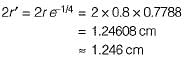
A single-phase, two wire transmission line, 15 km long, is made up of round conductors, each 0.8 cm radius, separated from each other by 40 cm. The equivalent diameter of a fictitious hollow, thin-walled conductor having the same inductance as the original line is given by
a)
1.557 cm '
b)
1.246 cm
c)
1.6 cm
d)
0.623 cm
|
|
Avik Iyer answered |
The fictitious conductor is one whose radius is r' and whose diameter is therefore,
A surge of 200 kV travels along an overhead line towards its junction with a cable. The surge impedance for the overhead line and cable are 450 Ω and 60 Ω respectively. The magnitude of the surge transmitted through cable is – (in kV)
Correct answer is between '47,47.1'. Can you explain this answer?
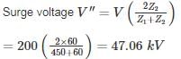
A surge of 200 kV travels along an overhead line towards its junction with a cable. The surge impedance for the overhead line and cable are 450 Ω and 60 Ω respectively. The magnitude of the surge transmitted through cable is – (in kV)
|
|
Ashwin Mukherjee answered |
Shunt capacitance in an EHV line is restored to- a)improve the stability
- b)reduce fault level
- c)improve the voltage
- d)none of the above
Correct answer is option 'C'. Can you explain this answer?
Shunt capacitance in an EHV line is restored to
a)
improve the stability
b)
reduce fault level
c)
improve the voltage
d)
none of the above
|
|
Srestha Gupta answered |
Shunt Capacitance in EHV Line
Shunt capacitance is an important parameter of an EHV transmission line. It is the capacitance between the line conductors and the ground.
Importance of Shunt Capacitance
- Shunt capacitance helps in maintaining the voltage level of the transmission line.
- It also helps in reducing the corona losses.
- Shunt capacitance is responsible for the charging current of the transmission line.
- It affects the overall transmission line impedance.
Restoring Shunt Capacitance to Improve Voltage
The shunt capacitance in an EHV line is restored to improve the voltage level of the transmission line. When the shunt capacitance is low, the voltage level of the transmission line decreases. This can lead to power losses and also affect the stability of the system.
By restoring the shunt capacitance, the voltage level can be improved. This is particularly important in long transmission lines where the voltage drop is significant. The shunt capacitance helps in maintaining the voltage level within acceptable limits.
Conclusion
Shunt capacitance is an important parameter of an EHV transmission line. It helps in maintaining the voltage level and reducing corona losses. Restoring shunt capacitance can improve the voltage level of the transmission line and ensure stable operation.
Unit of λ is- a)Rs/hr
- b)Rs/MW
- c)Rs/MWh
- d)MW/Rs
Correct answer is option 'C'. Can you explain this answer?
Unit of λ is
a)
Rs/hr
b)
Rs/MW
c)
Rs/MWh
d)
MW/Rs
|
|
Alok Khanna answered |
Measurement: A standardized quantity used to express the magnitude or amount of something.
Within the boiler, the steam has highest temperature in- a)superheater
- b)water tubes
- c)water walls
- d)water drum
Correct answer is option 'A'. Can you explain this answer?
Within the boiler, the steam has highest temperature in
a)
superheater
b)
water tubes
c)
water walls
d)
water drum
|
|
Avik Iyer answered |
Superheated steam has the highest temperature which comes out from super heater.
Consider the following statements:
1. AAC (All Aluminium conductors) are universaly employed for feeders as well as distributors.
2. The conductor size for a feeder is mainly governed by the permissible voltage drop in the line.
Which of the above statement(s) is/are true?- a)1 only
- b)1 and 2
- c)none
- d)2 only
Correct answer is option 'C'. Can you explain this answer?
Consider the following statements:
1. AAC (All Aluminium conductors) are universaly employed for feeders as well as distributors.
2. The conductor size for a feeder is mainly governed by the permissible voltage drop in the line.
Which of the above statement(s) is/are true?
1. AAC (All Aluminium conductors) are universaly employed for feeders as well as distributors.
2. The conductor size for a feeder is mainly governed by the permissible voltage drop in the line.
Which of the above statement(s) is/are true?
a)
1 only
b)
1 and 2
c)
none
d)
2 only
|
|
Isha Singh answered |
ACSR conductors are universally employed for distribution systems (feeders as well as distributors), AAC can be used for distribution purpose provided the spans are small.
Hence, statement-1 is false.
The conductor size for a feeder is mainly governed by current carrying capacity and overall economy. Hence, 2 is also a false statement.
Hence, statement-1 is false.
The conductor size for a feeder is mainly governed by current carrying capacity and overall economy. Hence, 2 is also a false statement.
The insulation resistance of a cable of 10 km length is 1 MΩ. The resistance for a length of 40 km is
- a)1 MΩ
- b)4 MΩ
- c)0.25 MΩ
- d)Can’t be determined
Correct answer is option 'C'. Can you explain this answer?
The insulation resistance of a cable of 10 km length is 1 MΩ. The resistance for a length of 40 km is
a)
1 MΩ
b)
4 MΩ
c)
0.25 MΩ
d)
Can’t be determined
|
|
Tanishq Majumdar answered |
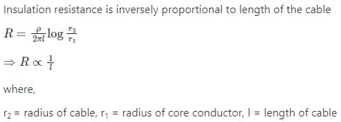
l1 = 10 km, R1 = 1 MΩ, l2 = 40 km

1/R2 = 40/10
R2 = 1/4 = 0.25 MΩ
The resistance and reactance of a short line are equal. At zero regulation the load will be- a)upf
- b)zpf
- c)0.707 lag
- d)0.707 lead
Correct answer is option 'D'. Can you explain this answer?
The resistance and reactance of a short line are equal. At zero regulation the load will be
a)
upf
b)
zpf
c)
0.707 lag
d)
0.707 lead
|
|
Harsh Kulkarni answered |
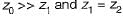
Zero regulation of a transmission line occurs at a leading power factor when φ = θ.
Since R = X
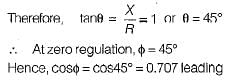
Since R = X
The sequence networks for a three-phase faults are connected in- a)series
- b)parallel
- c)series opposition
- d)none of the above
Correct answer is option 'D'. Can you explain this answer?
The sequence networks for a three-phase faults are connected in
a)
series
b)
parallel
c)
series opposition
d)
none of the above
|
|
Gayatri Menon answered |
A three-phase fault is a symmetrical fault where only positive sequence network (current exists).
Consider a power system with three identical generators. The transmission losses are negligible. One generator(G1) has a speed governor which maintains its speed constant at the rated value, while the other generators (G2 and G3) have governors with a drop of 5%. If the load of the system is increased, then in steady state.- a)Increase in G2 generation is more than an increase in G1 generation, While G3 remains constant.
- b)Increase in G1 generation is more than increase is G2 generation, while G3 remains constant.
- c)Generation of G1 increases, while that of G2 and G3 remains constant
- d)Increase in G1, G2 and G3 generation is equal.
Correct answer is option 'C'. Can you explain this answer?
Consider a power system with three identical generators. The transmission losses are negligible. One generator(G1) has a speed governor which maintains its speed constant at the rated value, while the other generators (G2 and G3) have governors with a drop of 5%. If the load of the system is increased, then in steady state.
a)
Increase in G2 generation is more than an increase in G1 generation, While G3 remains constant.
b)
Increase in G1 generation is more than increase is G2 generation, while G3 remains constant.
c)
Generation of G1 increases, while that of G2 and G3 remains constant
d)
Increase in G1, G2 and G3 generation is equal.
|
|
Poulomi Chopra answered |
Given power system with these identical generators G1 has Speed governor G2 and G3 has drop of 5% When load increased, in steady state generation of G1 is only increased while generation of G2 and G3 are unchanged.
In a hydroelectric plant, the available head is 80 m for a discharge 12m3/sec, and overall efficiency of the PowerStation of 80%. The specific weight of water is 9.81 k/m2. Then the power developed is – (in MW)
Correct answer is between '7.5,7.55'. Can you explain this answer?
In a hydroelectric plant, the available head is 80 m for a discharge 12m3/sec, and overall efficiency of the PowerStation of 80%. The specific weight of water is 9.81 k/m2. Then the power developed is – (in MW)
|
|
Jaya Rane answered |
P = WQHη KW
= 9.81 × 12 × 80 × 0.8
= 7534.08 KW = 7.53 MW
HVDC transmission is preferred to EHV AC because- a)HVDC terminal equipment are inexpensive
- b)VAR compensation is not required in HVDC system
- c)system reliability can be improved
- d)harmonic problem is avoided
Correct answer is option 'C'. Can you explain this answer?
HVDC transmission is preferred to EHV AC because
a)
HVDC terminal equipment are inexpensive
b)
VAR compensation is not required in HVDC system
c)
system reliability can be improved
d)
harmonic problem is avoided
|
|
Hrishikesh Yadav answered |
HVDC transmission is more reliable than EHV AC because it uses ground or sea return and therefore, in case of fault on a line it can still be used to supply power with the help of healthy lines.
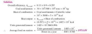
A steam power station spends Rs. 30 lakhs per annum for coal used in the station. The coal has a calorific value of 5000 kcal/kg and costs Rs. 300 per ton. If the station has thermal efficiency of 33% and electrical efficiency of 90%, find the average load on the station. (in kW)
Correct answer is between '1960,1980'. Can you explain this answer?
A steam power station spends Rs. 30 lakhs per annum for coal used in the station. The coal has a calorific value of 5000 kcal/kg and costs Rs. 300 per ton. If the station has thermal efficiency of 33% and electrical efficiency of 90%, find the average load on the station. (in kW)
|
|
Raj Singh answered |
Ans.
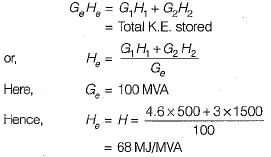
A 500-MVA synchronous machine has H1 = 4.6 MJ/MVA, and a 1500 MVA machine has H2 = 3.0 MJ/MVA. The two machines operate in parallel in a power station. The equivalent H constant for the two, relative to a 100 MVA base will be- a)22 MJ/MVA
- b)45 MJ/MVA
- c)52 MJ/MVA
- d)68 MJ/MVA
Correct answer is option 'D'. Can you explain this answer?
A 500-MVA synchronous machine has H1 = 4.6 MJ/MVA, and a 1500 MVA machine has H2 = 3.0 MJ/MVA. The two machines operate in parallel in a power station. The equivalent H constant for the two, relative to a 100 MVA base will be
a)
22 MJ/MVA
b)
45 MJ/MVA
c)
52 MJ/MVA
d)
68 MJ/MVA
|
|
Anoushka Choudhury answered |
We know that,
If the initial acceleration power of a 100 MVA, 50 Hz synchronous generator having H= 5 MJ/MVA is Xpu, the initial acceleration in elec-deg/s2 and the inertia constant in M J-s/ele-deg respectively will be - a)31.4X, 18
- b)1800X, 0.056
- c)X/1800, 0.056
- d)X/31.4, 18
Correct answer is option 'B'. Can you explain this answer?
If the initial acceleration power of a 100 MVA, 50 Hz synchronous generator having H= 5 MJ/MVA is Xpu, the initial acceleration in elec-deg/s2 and the inertia constant in M J-s/ele-deg respectively will be
a)
31.4X, 18
b)
1800X, 0.056
c)
X/1800, 0.056
d)
X/31.4, 18
|
|
Maulik Choudhury answered |
From swing equation,
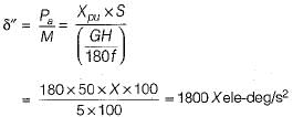
Also, inertia constant,
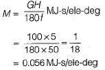
Also, inertia constant,
The incremental transmission loss of a plant can’t be a- a)negative quantity
- b)positive quantity
- c)a zero value
- d)non-zero value
Correct answer is option 'C'. Can you explain this answer?
The incremental transmission loss of a plant can’t be a
a)
negative quantity
b)
positive quantity
c)
a zero value
d)
non-zero value
|
|
Kajal Mukherjee answered |
The incremental transmission loss of a plant can be positive, a non-zero value but, can’t be zero.
Pilot relaying schemes are used for protection of- a)bus bars
- b)transformers
- c)transmission lines
- d)instrument transfomers
Correct answer is option 'C'. Can you explain this answer?
Pilot relaying schemes are used for protection of
a)
bus bars
b)
transformers
c)
transmission lines
d)
instrument transfomers
|
|
Anshika Khanna answered |
Pilot relaying schemes provide high speed protection for transmission lines.
Consider the following phenomenon occuring in a power system:
1. Corona loss
2. Charging current
3. Ferranti effect
4. Dielectric loss
5. Skin effect
Which of the above are associated with transmission lines?- a)1,3 and 5
- b)2, 3, 4 and 5
- c)3, 2 and 4
- d)1,2, 3 and 5
Correct answer is option 'D'. Can you explain this answer?
Consider the following phenomenon occuring in a power system:
1. Corona loss
2. Charging current
3. Ferranti effect
4. Dielectric loss
5. Skin effect
Which of the above are associated with transmission lines?
1. Corona loss
2. Charging current
3. Ferranti effect
4. Dielectric loss
5. Skin effect
Which of the above are associated with transmission lines?
a)
1,3 and 5
b)
2, 3, 4 and 5
c)
3, 2 and 4
d)
1,2, 3 and 5
|
|
Gargi Basak answered |
Dielectric loss occurs in underground cables not in a transmission line.
For a synchronous phase modifier the load angle is- a)00
- b)250
- c)300
- d)None of these
Correct answer is option 'A'. Can you explain this answer?
For a synchronous phase modifier the load angle is
a)
00
b)
250
c)
300
d)
None of these
|
|
Arya Mukherjee answered |
Synchronous phase modifier is an overexcited synchronous motor operating on no-load under wide variation of excitation. For no-load operation, δ = 0.
Three synchronous generators, each of which is rated to 100 MVA, 11 KV, have an impedance per unit of 0.15. If all three generators are replaced by a single equivalent generator, what will be the effective per unit impedance of each generator?- a)0.45
- b)0.15
- c)0.025
- d)0.05
Correct answer is option 'D'. Can you explain this answer?
Three synchronous generators, each of which is rated to 100 MVA, 11 KV, have an impedance per unit of 0.15. If all three generators are replaced by a single equivalent generator, what will be the effective per unit impedance of each generator?
a)
0.45
b)
0.15
c)
0.025
d)
0.05
|
|
Mahesh Singh answered |
Calculation:
Given data:
- Number of generators: 3
- Rating of each generator: 100 MVA
- Voltage rating: 11 kV
- Impedance per unit: 0.15
To find:
- Effective per unit impedance of each generator when replaced by a single equivalent generator
Step 1: Calculation of equivalent impedance
The total impedance of the three generators connected in parallel can be calculated as follows:
Zeq = Zg / N
Where,
Zeq = Equivalent impedance
Zg = Impedance of a single generator
N = Number of generators
Given that Zg = 0.15, and N = 3, we can substitute these values into the equation:
Zeq = 0.15 / 3
Zeq = 0.05
Therefore, the equivalent impedance of the three generators connected in parallel is 0.05 per unit.
Step 2: Calculation of effective per unit impedance
To find the effective per unit impedance of each generator, we need to divide the equivalent impedance by the number of generators:
Effective per unit impedance = Zeq / N
Given that Zeq = 0.05 and N = 3, we can substitute these values into the equation:
Effective per unit impedance = 0.05 / 3
Effective per unit impedance = 0.0167
Therefore, the effective per unit impedance of each generator when replaced by a single equivalent generator is 0.0167.
Step 3: Comparing the options
a) 0.45 - This is not the correct answer.
b) 0.15 - This is not the correct answer.
c) 0.025 - This is not the correct answer.
d) 0.05 - This is the correct answer.
Therefore, option D, 0.05, is the correct answer.
Conclusion:
When three synchronous generators with an impedance per unit of 0.15 are replaced by a single equivalent generator, the effective per unit impedance of each generator becomes 0.05.
The series impedance matrix of a short three-phase transmission line in phase coordinates is 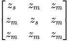 . If the positive sequence impedance is (1 + j 10) Ω, and the zero sequence is (4 + j 31) Ω, then the imaginary part of Zm (in Ω) is _______ (up to 2 decimal places).
Correct answer is '7'. Can you explain this answer?
The series impedance matrix of a short three-phase transmission line in phase coordinates is . If the positive sequence impedance is (1 + j 10) Ω, and the zero sequence is (4 + j 31) Ω, then the imaginary part of Zm (in Ω) is _______ (up to 2 decimal places).
. If the positive sequence impedance is (1 + j 10) Ω, and the zero sequence is (4 + j 31) Ω, then the imaginary part of Zm (in Ω) is _______ (up to 2 decimal places).

|
Cstoppers Instructors answered |
Given that, positive sequence impedance (Z1) = (1 + j10) Ω
Zero sequence impedance (Z0) = (4 + j31) Ω
We know that, Z1 = Zs – Zm
and Z0 = Zs + 2Zm
Z1 = 1 + j10 = Zs – Zm → (1)
and Z0 = 4 + j31 = Zs + 2Zm → (2)
from equations (1) and (2)
⇒ Zm = 1 + j7
Imaginary part of Zm = 7 Ω.
For a 35 km transmission line having a lumped impedance of the line as 20 ohms, is required to be shown in the ABCD form, it is given as- a)

- b)

- c)

- d)

Correct answer is option 'A'. Can you explain this answer?
For a 35 km transmission line having a lumped impedance of the line as 20 ohms, is required to be shown in the ABCD form, it is given as
a)
b)
c)
d)
|
|
Pooja Patel answered |
From the given length, it is a short TL. Hence,
Then ABCD paramteres of this circuit is
Then ABCD paramteres of this circuit is
When generating units are loaded to equal incremental costs, it results in- a)minimum fuel costs
- b)fuel costs are at a maximum
- c)fuel costs are not affected
- d)maximum loading of generating units
Correct answer is option 'A'. Can you explain this answer?
When generating units are loaded to equal incremental costs, it results in
a)
minimum fuel costs
b)
fuel costs are at a maximum
c)
fuel costs are not affected
d)
maximum loading of generating units
|
|
Parth Ghoshal answered |
To minimize the total fuel cost, the generating units must operate at equal incremental cost of production.
Galvanised steel is generally used as:- a)stray wire
- b)earth wire
- c)A, B, D
- d)structural components
Correct answer is option 'C'. Can you explain this answer?
Galvanised steel is generally used as:
a)
stray wire
b)
earth wire
c)
A, B, D
d)
structural components
|
|
Sanya Agarwal answered |
- If the wires are made up with some other ordinary steels, rust and corrosion attacked the wire after some time due to the environmental wet conditions.
- A layer of zinc oxide can be provided on the steel wire by some chemical process.
- This zinc oxide layer protects the steel wire from the rust and corrosion effects. That’s why galvanized steel is used in many places.
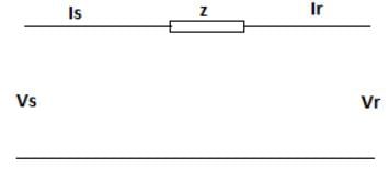
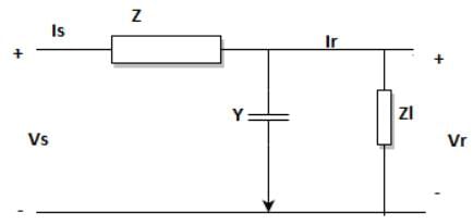
The transmission line equations are given by the below set of equations based on the line diagram as given. Identify the missing term marked as ’?’.
Vs = A*Vr + B*Ir
Is = C*Vr + ?*Ir
- a)1+YZ
- b)Z
- c)Y
- d)1
Correct answer is option 'D'. Can you explain this answer?
The transmission line equations are given by the below set of equations based on the line diagram as given. Identify the missing term marked as ’?’.
Vs = A*Vr + B*Ir
Is = C*Vr + ?*Ir
Vs = A*Vr + B*Ir
Is = C*Vr + ?*Ir
a)
1+YZ
b)
Z
c)
Y
d)
1

|
Naroj Boda answered |
Using KVL to the line diagram,
Vs = (1+YZ)*Vr + Z*Ir
Is = Y*Vr + Ir.
Vs = (1+YZ)*Vr + Z*Ir
Is = Y*Vr + Ir.
A station operates with a load factor and plant capacity factor of 0.75, with a maximum demand of 100 MW. The reserve capacity is- a)100 MW
- b)75 MW
- c)0 MW
- d)133.33 MW
Correct answer is option 'C'. Can you explain this answer?
A station operates with a load factor and plant capacity factor of 0.75, with a maximum demand of 100 MW. The reserve capacity is
a)
100 MW
b)
75 MW
c)
0 MW
d)
133.33 MW
|
|
Sanchita Choudhary answered |
Load Factor and Plant Capacity Factor
Load factor is the ratio of average load to the maximum demand, and plant capacity factor is the ratio of actual output to the maximum capacity.
Load factor = (Average load) / (Maximum demand)
Plant capacity factor = (Actual output) / (Maximum capacity)
Given load factor and plant capacity factor are 0.75, the maximum demand is 100 MW.
Reserve Capacity
Reserve capacity is the amount of extra capacity available to meet sudden increases in demand or unexpected outages. It is calculated by subtracting the maximum demand from the maximum capacity.
Reserve capacity = Maximum capacity - Maximum demand
Since the load factor and plant capacity factor are both 0.75, it means that the actual output is 75 MW, which is 75% of the maximum capacity. Therefore, the maximum capacity is:
Maximum capacity = Actual output / Plant capacity factor
Maximum capacity = 75 MW / 0.75
Maximum capacity = 100 MW
Thus, the reserve capacity is:
Reserve capacity = Maximum capacity - Maximum demand
Reserve capacity = 100 MW - 100 MW
Reserve capacity = 0 MW
Therefore, the correct answer is option C, which is 0 MW.
A dc line carries- a)same power as an ac line
- b)less power than an equivalent ac line
- c)more power than the ac line
- d)both (a) and (c)
Correct answer is option 'C'. Can you explain this answer?
A dc line carries
a)
same power as an ac line
b)
less power than an equivalent ac line
c)
more power than the ac line
d)
both (a) and (c)
|
|
Pranjal Datta answered |
Due to requirement of less number of conductors, a dc line carries more power than a ac line, (losses of the line reduces in HVDC).
The line current in a three phase unbalanced load are Ia = 4 + j6, Ib = 2 - j2, Ic = -3 + j2, then zero sequence component of current will be- a)3 + j6
- b)9 + j10
- c)1 + j2
- d)3 - j6
Correct answer is option 'C'. Can you explain this answer?
The line current in a three phase unbalanced load are Ia = 4 + j6, Ib = 2 - j2, Ic = -3 + j2, then zero sequence component of current will be
a)
3 + j6
b)
9 + j10
c)
1 + j2
d)
3 - j6
|
|
Pooja Patel answered |
Concept:
The relation between the line currents in terms of the symmetrical components of currents is given below.
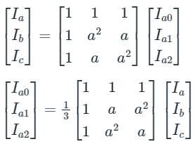
The relation between the line currents in terms of the symmetrical components of currents is given below.
Ia0 = Zero Sequence Component of Current
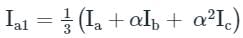
Ia1 = Positive Sequence Component of Current
Ia2 = Negative Sequence Component of Current
a = 1∠120°, which represents the rotation of 120° in the clockwise direction.
a2 = 1∠-120° or 1∠240° in anticlockwise direction or clockwise direction, respectively.
1 + a + a2 = 0
Calculation:
Given that
Ia = 4 + j6, Ib = 2 - j2, Ic = -3 + j2
Zero sequence component of current,
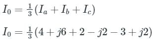
∴ I0 = 1 + j2 A
There is a problem of high transient over voltages while interrupting- a)capacitive currents
- b)inductive currents
- c)heavy short circuit current
- d)(a) or (c)
Correct answer is option 'A'. Can you explain this answer?
There is a problem of high transient over voltages while interrupting
a)
capacitive currents
b)
inductive currents
c)
heavy short circuit current
d)
(a) or (c)
|
|
Palak Verma answered |
High transient over voltages occurs in power system due to formation of capacitance across the breaker poles. These are also called switching over voltages.
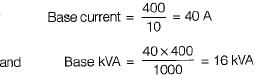
The base impedance and base voltage for a given power system are 10Ω and 400 V respectively. The base kVA and the base current will be respectively- a)16000 kVA and 40 A
- b)4 kVA and 16 A
- c)16 kVA and 40 A
- d)4 kVA and 400 A
Correct answer is option 'C'. Can you explain this answer?
The base impedance and base voltage for a given power system are 10Ω and 400 V respectively. The base kVA and the base current will be respectively
a)
16000 kVA and 40 A
b)
4 kVA and 16 A
c)
16 kVA and 40 A
d)
4 kVA and 400 A
|
|
Maulik Choudhury answered |
For a given power system, its zero and maximum regulation will occur at the impedance angle of- a)45
- b)90
- c)0
- d)60
Correct answer is option 'A'. Can you explain this answer?
For a given power system, its zero and maximum regulation will occur at the impedance angle of
a)
45
b)
90
c)
0
d)
60
|
|
Aditya Basu answered |
Zero and maximum regulation in a power system occur at the impedance angle of 45 degrees. This can be explained by considering the nature of reactive power flow in a power system and the relationship between the voltage and current.
1. Reactive Power Flow:
Reactive power is the power that oscillates between the generation and consumption points in a power system. It is responsible for maintaining the voltage levels and stability in the system. Reactive power flow depends on the phase difference between the voltage and current.
2. Voltage and Current Relationship:
The voltage and current in a power system are related by the impedance angle, which is the phase difference between them. The impedance angle determines the power factor of the system and affects the flow of reactive power.
3. Regulation:
Regulation refers to the ability of a power system to maintain a steady voltage level at different load conditions. It is measured as the percentage change in voltage from no load to full load.
4. Zero Regulation:
Zero regulation occurs when the impedance angle is 45 degrees. At this angle, the reactive power flow is balanced, and the system is able to maintain a constant voltage level regardless of the load variations. This means that the voltage at the load remains unchanged from no load to full load.
5. Maximum Regulation:
Maximum regulation occurs when the impedance angle is different from 45 degrees. At angles other than 45 degrees, the reactive power flow becomes unbalanced, leading to a change in voltage at the load with varying load conditions. This results in a decrease in regulation, as the voltage at the load deviates from the desired level.
In conclusion, the zero and maximum regulation in a power system occur at the impedance angle of 45 degrees. At this angle, the reactive power flow is balanced, and the system is able to maintain a constant voltage level regardless of the load variations. At angles other than 45 degrees, the reactive power flow becomes unbalanced, leading to a change in voltage at the load and a decrease in regulation.
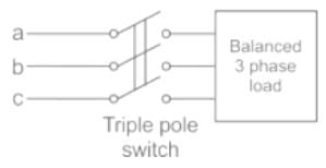
A balanced 3-phase load is supplied from a 3-phase supply. The contact in line c of the triple pole switch contactor fails to connect when switched on. If the line currents in lines a and b record 25A each, then the positive sequence component of the current is
- a)14.4 ∠30° A
- b)25.0 ∠-30° A
- c)14.4 ∠-30° A
- d)25 ∠80° A
Correct answer is option 'C'. Can you explain this answer?
A balanced 3-phase load is supplied from a 3-phase supply. The contact in line c of the triple pole switch contactor fails to connect when switched on. If the line currents in lines a and b record 25A each, then the positive sequence component of the current is
a)
14.4 ∠30° A
b)
25.0 ∠-30° A
c)
14.4 ∠-30° A
d)
25 ∠80° A
|
|
Pooja Patel answered |
The contact in line C of the triple pole switch contactor fails to connect when switched on.
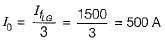
⇒ Ic = 0 A
And Ia + Ib = 0
⇒ Ia = -Ib
⇒ Ia = 25 ∠0°, Ib = 25 ∠-180°
Positive sequence current,
Positive sequence current,
= 1/3(25 ∠ 0∘ + 1∠120 × 25∠ −180)
= 14.4 ∠ -30°
In a dc transmision- a)it is necessary for the sending and receiving end to be operated in synchronism.
- b)the effects of inductive and capacitive reactances are greater than in ac transmission line of the same rating.
- c)there are no effects due to inductive and capacitive reactances.
- d)power transfer capability is limited by stability considerations.
Correct answer is option 'C'. Can you explain this answer?
In a dc transmision
a)
it is necessary for the sending and receiving end to be operated in synchronism.
b)
the effects of inductive and capacitive reactances are greater than in ac transmission line of the same rating.
c)
there are no effects due to inductive and capacitive reactances.
d)
power transfer capability is limited by stability considerations.
|
|
Gayatri Menon answered |
As operating frequency, f = 0 therefore, there is no effect of XL and XC.

Which of the following rotor is used in thermal power plants? - a)squirrel cage rotor
- b)salient pole rotor
- c)either of these
- d)cylindrical rotor
Correct answer is option 'D'. Can you explain this answer?
Which of the following rotor is used in thermal power plants?
a)
squirrel cage rotor
b)
salient pole rotor
c)
either of these
d)
cylindrical rotor
|
|
Prisha Sengupta answered |
Rotor in Thermal Power Plants
In thermal power plants, the rotor used is the cylindrical rotor.
Explanation:
- The cylindrical rotor is a type of rotor used in synchronous generators.
- It consists of a solid cylinder of magnetic material with slots on its surface to accommodate the field winding.
- The rotor is mounted on a shaft and rotates inside the stator winding.
- The stator winding in thermal power plants is made up of a series of coils arranged in a circular pattern around the rotor.
- When the rotor rotates, the magnetic field created by the field winding on the rotor interacts with the stator winding, inducing an electrical current in the stator winding.
- This current is then transmitted to the grid through a transformer and power lines.
- The cylindrical rotor is preferred in thermal power plants because it can handle a large amount of power and is highly efficient.
- It is also more durable than other types of rotors and can operate at high temperatures without any significant loss of efficiency.
Conclusion:
Thus, the cylindrical rotor is the most suitable rotor for use in thermal power plants due to its high efficiency, durability, and ability to handle large amounts of power.
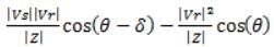
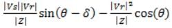
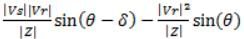
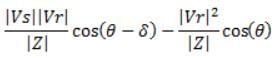
The receiving end active power for a short transmission line is (where the angles have their usual meanings)- a)
- b)
- c)
- d)
Correct answer is option 'A'. Can you explain this answer?
The receiving end active power for a short transmission line is (where the angles have their usual meanings)
a)
b)
c)
d)
|
|
Pooja Patel answered |
Receiving end active power for a short transmission line is
Which of the following statement is true?- a)At higher voltage, cost of transmission is increased
- b)At higher voltage, cost of transmission is decreased
- c)efficiency decreased
- d)all of the above
Correct answer is option 'B'. Can you explain this answer?
Which of the following statement is true?
a)
At higher voltage, cost of transmission is increased
b)
At higher voltage, cost of transmission is decreased
c)
efficiency decreased
d)
all of the above
|
|
Athul Banerjee answered |
At higher voltage, cost of transmission is decreased.
Explanation:
Higher voltage transmission has several advantages over lower voltage transmission. Let's discuss them in detail:
1. Reduced Current:
- When the voltage is increased, the current required for the same power transmission decreases.
- According to Ohm's Law (V = I × R), for the same power (P), if voltage (V) increases, the current (I) decreases.
- As a result, lower current reduces resistive losses in the transmission lines.
2. Reduced Resistive Losses:
- The resistive losses in a transmission line are given by the formula P_loss = I^2 × R, where I is the current and R is the resistance of the line.
- As discussed earlier, higher voltage transmission reduces the current, which in turn reduces the resistive losses.
- Lower resistive losses mean that a greater amount of power reaches its destination, resulting in increased efficiency.
3. Reduced Size of Conductors:
- As the current decreases with higher voltage transmission, it allows for the use of smaller conductors.
- Smaller conductors are cheaper and require less material, reducing the overall cost of transmission line construction.
4. Increased Efficiency:
- Higher voltage transmission reduces resistive losses and allows for the transmission of more power with the same amount of current.
- This increased efficiency means that less power is wasted during transmission, resulting in cost savings.
5. Improved Voltage Regulation:
- Higher voltage transmission helps to maintain voltage levels within acceptable limits.
- When power is transmitted over long distances, voltage drops occur due to resistive losses. With higher voltage, the initial voltage at the source is higher, compensating for the voltage drop, and ensuring that the desired voltage is maintained at the load end.
Conclusion:
Based on the above explanations, it is clear that at higher voltage, the cost of transmission is decreased. This is mainly due to the reduced current, lower resistive losses, reduced size of conductors, increased efficiency, and improved voltage regulation.
Which of the following is not the advantage of higher transmission voltage:- a)Power transfer capability of the transmission line is reduced
- b)Transmission line losses are reduced
- c)Area of cross section and volume of the conductor is reduced
- d)Power transfer capability of the transmission line is increased
Correct answer is option 'A'. Can you explain this answer?
Which of the following is not the advantage of higher transmission voltage:
a)
Power transfer capability of the transmission line is reduced
b)
Transmission line losses are reduced
c)
Area of cross section and volume of the conductor is reduced
d)
Power transfer capability of the transmission line is increased
|
|
Ritika Mukherjee answered |
Introduction:
Higher transmission voltage is advantageous in electrical power systems for various reasons. It offers several benefits such as reduced transmission line losses, reduced conductor size, and increased power transfer capability. However, one of the options mentioned, "Power transfer capability of the transmission line is reduced," is not an advantage of higher transmission voltage.
Explanation:
Let's analyze each option to understand why option 'A' is the correct answer:
a) Power transfer capability of the transmission line is reduced:
This option is not an advantage of higher transmission voltage. In fact, higher transmission voltage leads to increased power transfer capability. It allows for the transmission of more power over longer distances without significant voltage drops. Higher voltage reduces the line losses, enabling the system to deliver more power efficiently.
b) Transmission line losses are reduced:
Higher transmission voltage significantly reduces the losses in the transmission lines. According to Ohm's law, power losses in a transmission line are directly proportional to the square of the current passing through it. By increasing the transmission voltage, the current can be reduced for the same power transfer, resulting in lower losses.
c) Area of cross section and volume of the conductor is reduced:
With higher transmission voltage, the current required for a given power transfer is reduced. This reduction in current allows for smaller conductor sizes and reduces the cross-sectional area and volume of the conductor. Smaller conductors are cost-effective and easier to install and maintain.
d) Power transfer capability of the transmission line is increased:
This option correctly states the advantage of higher transmission voltage. Increased voltage allows for the transmission of more power through the same transmission line. By reducing the current, higher voltages enable the system to transfer more power efficiently, reducing line losses.
Conclusion:
In summary, higher transmission voltage offers several advantages in electrical power systems, including reduced transmission line losses, reduced conductor size, and increased power transfer capability. The only option that does not align with the advantages of higher transmission voltage is "Power transfer capability of the transmission line is reduced" (option 'A').
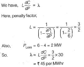
A generator is supplying a load. An incremental change in load of 4 MW requires generation to be increased by 6 MW. The cost at plant bus is ₹ 30/MWhr. The incremental cost at the receiving end is- a)₹ 30/MWhr
- b)₹ 5/MWhr
- c)₹ 33.4/MWhr
- d)₹ 6.0/MWhr
Correct answer is option 'B'. Can you explain this answer?
A generator is supplying a load. An incremental change in load of 4 MW requires generation to be increased by 6 MW. The cost at plant bus is ₹ 30/MWhr. The incremental cost at the receiving end is
a)
₹ 30/MWhr
b)
₹ 5/MWhr
c)
₹ 33.4/MWhr
d)
₹ 6.0/MWhr
|
|
Raj Desai answered |
Chapter doubts & questions for Power Systems - Topicwise Question Bank for Electrical Engineering 2025 is part of Electrical Engineering (EE) exam preparation. The chapters have been prepared according to the Electrical Engineering (EE) exam syllabus. The Chapter doubts & questions, notes, tests & MCQs are made for Electrical Engineering (EE) 2025 Exam. Find important definitions, questions, notes, meanings, examples, exercises, MCQs and online tests here.
Chapter doubts & questions of Power Systems - Topicwise Question Bank for Electrical Engineering in English & Hindi are available as part of Electrical Engineering (EE) exam.
Download more important topics, notes, lectures and mock test series for Electrical Engineering (EE) Exam by signing up for free.

Signup to see your scores go up within 7 days!
Study with 1000+ FREE Docs, Videos & Tests
10M+ students study on EduRev
|
© EduRev
|
Education Revolution
|


|


Signup to see your scores
go up within 7 days!
Access 1000+ FREE Docs, Videos and Tests
Takes less than 10 seconds to signup