


All Exams > Electrical Engineering (EE) > Power Systems > All Questions
All questions of Load Flow Studies for Electrical Engineering (EE) Exam
Number of iterations required for convergence of a load flow algorithm increases significantly with increase of number of buses with- a)G-S load flow algorithm
- b)N-R load flow algorithm
- c)both G-S and N-R load flow algorithms
- d)Fast decoupled load flow algorithm
Correct answer is option 'A'. Can you explain this answer?
Number of iterations required for convergence of a load flow algorithm increases significantly with increase of number of buses with
a)
G-S load flow algorithm
b)
N-R load flow algorithm
c)
both G-S and N-R load flow algorithms
d)
Fast decoupled load flow algorithm
| | Pooja Patel answered |
Load flow study:
- Load flow study determines the operating state of the system for a given loading.
- Load flow solves a set of simultaneous non-linear algebraic power equations for the two unknown variables (|V| and ∠δ) at each node in a system.
- The output of the load flow analysis is the voltage and phase angle, real and reactive power (both sides in each line), line losses, and slack bus power.
- Gauss seidel, Newton Raphson, and Fast decoupled load flow method are the different load flow methods.
- The number of iterations required for convergence of a load flow algorithm increases significantly with the increase of the number of buses with G-S load flow algorithm.
- The fast decoupled load flow method gives an approximate load flow solution because it uses several assumptions. Accuracy depends on the power mismatch vector tolerance.
- The fast decoupled load flow method is an extension of the Newton-Raphson method formulated in polar coordinates with certain approximations, which results in a fast algorithm for load flow solution.
- The fast decoupled method requires a greater number of iterations than the Newton-Raphson method.

A 183 – bus power system has 150 PQ buses and 32 PV buses. In the general case, to obtain the load flow solution using Newton – Raphson method in polar coordinates, the minimum number of simultaneous equations to be solved is_________.
Correct answer is '332.00'. Can you explain this answer?
A 183 – bus power system has 150 PQ buses and 32 PV buses. In the general case, to obtain the load flow solution using Newton – Raphson method in polar coordinates, the minimum number of simultaneous equations to be solved is_________.
| | Alok Khanna answered |
183 is a three-digit number. It is an odd number and is also a prime number. The factors of 183 are 1 and 183.
An infinite bus-bar has- a)constant voltage
- b)constant frequency
- c)infinite voltage
- d)both (a) and (b)
Correct answer is option 'D'. Can you explain this answer?
An infinite bus-bar has
a)
constant voltage
b)
constant frequency
c)
infinite voltage
d)
both (a) and (b)
 | Pioneer Academy answered |
Concept:
The bus whose voltage and frequency remain constant even after the variation in the load is known as the infinite bus.
The alternators operating in parallel in a power system are the example of the infinite bus. The on and off of any of the alternators will not affect the working of the power system.
- The capacity of a parallel operating system is enormous, their voltage and frequency remain constant even after the disturbance of the load.
- The connection and disconnection of any of the machines will not affect the magnitude and phase of voltage and frequency of an infinite bus.
- In an infinite bus system, the voltage and frequency always remain constant.
- The synchronous impedance of the bus is low because of the parallel operations of the machine.
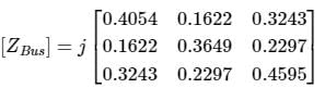
The bus impedance matrix of a 4 – bus power system is given by
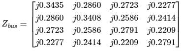
A branch having an impedance of j 0.2 Ω is connected between bus 2 and the reference Then the values of Z22,new and Z23,new of the bus impedance matrix of the modified network are respectively.- a)j0.5408 Ω and j0.4586 Ω
- b)j0.1260 Ω and j0.0956 Ω
- c)j0.5408 Ω and j0.0956 Ω
- d)j0.1260 Ω and j0.1630 Ω
Correct answer is option 'B'. Can you explain this answer?
The bus impedance matrix of a 4 – bus power system is given by
A branch having an impedance of j 0.2 Ω is connected between bus 2 and the reference Then the values of Z22,new and Z23,new of the bus impedance matrix of the modified network are respectively.
A branch having an impedance of j 0.2 Ω is connected between bus 2 and the reference Then the values of Z22,new and Z23,new of the bus impedance matrix of the modified network are respectively.
a)
j0.5408 Ω and j0.4586 Ω
b)
j0.1260 Ω and j0.0956 Ω
c)
j0.5408 Ω and j0.0956 Ω
d)
j0.1260 Ω and j0.1630 Ω
| | Pooja Patel answered |
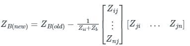
New element Zb = j0.2Ω is connected in ith bus and reference bus i = 2, n = 4 so
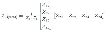
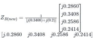
Given that we are required to find only Z22, Z23
= j 0.1260

= j 0.0956
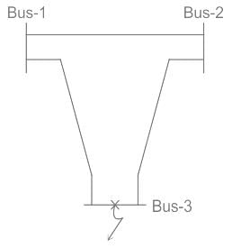
Z-bus matrix of 3 bus power system is given below, due to fault at bus-3 ( as shown). Find the final voltage at bus1 and bus-2. Consider the all bus voltage as 1 p.u. prior to the fault. Bus impedances are in p.u. values.
- a)V1 = 0.29 p.u, V2 = 0.50 p.u
- b)V1 = 0.50 p.u, V2 = 0.29 p.u
- c)V1 = 0.40 p.u, V2 = 0.50 p.u
- d)V1 = 0.50 p.u, V2 = 0.40 p.u
Correct answer is option 'A'. Can you explain this answer?
Z-bus matrix of 3 bus power system is given below, due to fault at bus-3 ( as shown). Find the final voltage at bus1 and bus-2. Consider the all bus voltage as 1 p.u. prior to the fault. Bus impedances are in p.u. values.
a)
V1 = 0.29 p.u, V2 = 0.50 p.u
b)
V1 = 0.50 p.u, V2 = 0.29 p.u
c)
V1 = 0.40 p.u, V2 = 0.50 p.u
d)
V1 = 0.50 p.u, V2 = 0.40 p.u
| | Pooja Patel answered |
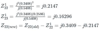
Fault current at bus 3 is given by If3 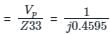
= -j 2.1762 p.u (Vp = voltage of the bus prior to fault).
Due to fault at bus-3 its voltage becomes 0 V and the voltage of Bus-1 and Bus-2 will also reduce.
Changes in voltage can be found with the help of the Z-bus matrix as.
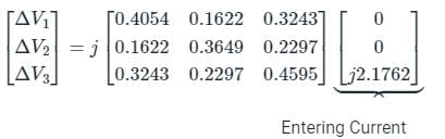
ΔV1 = (j0.3243)(j2.1762) = - 0.7057
ΔV2 = (j0.2297)(j2.1762) = - 0.4998
Final voltage at Bus-1: Vf1 = Vp1 + ΔV1 = 1 - 0.7057 = 0.2943 p.u
Final voltage at Bus-2: Vf2 = Vp2 + ΔV2 = 1 - 0.4998 = 0.5002 p.u
Due to fault at bus-3 its voltage becomes 0 V and the voltage of Bus-1 and Bus-2 will also reduce.
Changes in voltage can be found with the help of the Z-bus matrix as.
ΔV1 = (j0.3243)(j2.1762) = - 0.7057
ΔV2 = (j0.2297)(j2.1762) = - 0.4998
Final voltage at Bus-1: Vf1 = Vp1 + ΔV1 = 1 - 0.7057 = 0.2943 p.u
Final voltage at Bus-2: Vf2 = Vp2 + ΔV2 = 1 - 0.4998 = 0.5002 p.u
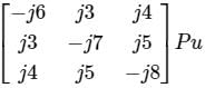
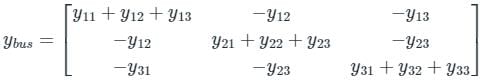
The Ybus matrix of a two-bus power system having two identical parallel lines connected between them in pu is given as 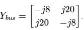
The magnitude of the series reactance of each line in pu (round off up to one decimal place) is ____________.
Correct answer is between '0.095,0.105'. Can you explain this answer?
The Ybus matrix of a two-bus power system having two identical parallel lines connected between them in pu is given as
The magnitude of the series reactance of each line in pu (round off up to one decimal place) is ____________.
The magnitude of the series reactance of each line in pu (round off up to one decimal place) is ____________.
| | Pioneer Academy answered |
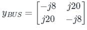
Let series impedance each line is jy pu
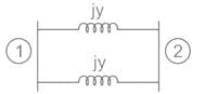
From yBUS, Y12 = - y12 = j20
⇒ y12 = -j20
From the diagram
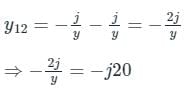
⇒ y = j 0.1 pu
The figure shows the per-phase representation of a phase-shifting transformer connected between buses 1 and 2, where α is a complex number with non-zero real and imaginary parts.
For the given circuit Ybus and Zbus are bus admittance matrix and bus impedance matrix respectively, each of size 2 × 2. Which one of the following statements is true?- a)Both Ybus and Zbus are symmetric
- b)Ybus is symmetric and Zbus is unsymmetric
- c)Ybus is unsymmetric and Zbus is symmetric
- d)Both Ybus and Zbus are unsymmetric
Correct answer is option 'D'. Can you explain this answer?
The figure shows the per-phase representation of a phase-shifting transformer connected between buses 1 and 2, where α is a complex number with non-zero real and imaginary parts.
For the given circuit Ybus and Zbus are bus admittance matrix and bus impedance matrix respectively, each of size 2 × 2. Which one of the following statements is true?
For the given circuit Ybus and Zbus are bus admittance matrix and bus impedance matrix respectively, each of size 2 × 2. Which one of the following statements is true?
a)
Both Ybus and Zbus are symmetric
b)
Ybus is symmetric and Zbus is unsymmetric
c)
Ybus is unsymmetric and Zbus is symmetric
d)
Both Ybus and Zbus are unsymmetric
 | Naroj Boda answered |
T - parameter matrix,
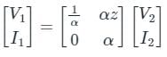
Since A ≠ D, the network is asymmetric and hence Ybus and Zbus will also be asymmetric.
For a power system network with n nodes, Z33 of its bus impedance matrix is j0.5 per unit. The voltage at node 3 is 1.3∠-10° per unit. If a capacitor having reactance of –j3.5 per unit is now added to the network between node 3 and the reference node, the current drawn by the capacitor per unit is- a)0.325∠-100°
- b)0.325∠ 80°
- c)0.433∠-100°
- d)0.433∠80°
Correct answer is option 'D'. Can you explain this answer?
For a power system network with n nodes, Z33 of its bus impedance matrix is j0.5 per unit. The voltage at node 3 is 1.3∠-10° per unit. If a capacitor having reactance of –j3.5 per unit is now added to the network between node 3 and the reference node, the current drawn by the capacitor per unit is
a)
0.325∠-100°
b)
0.325∠ 80°
c)
0.433∠-100°
d)
0.433∠80°
| | Prisha Iyer answered |
Understanding the Problem
To find the current drawn by the capacitor connected at node 3, we need to analyze the voltage and reactance involved.
Given Data
- Reactance of capacitor, Xc = -j3.5 per unit
- Voltage at node 3, V3 = 1.3∠-10° per unit
Calculating Capacitor Current
The current drawn by a capacitor can be calculated using the formula:
I = V / Xc
Where:
- I is the current drawn by the capacitor
- V is the voltage across the capacitor
- Xc is the reactance of the capacitor
Applying the Values
1. Convert Voltage to Rectangular Form:
V3 = 1.3∠-10°
V3 = 1.3 * (cos(-10°) + j*sin(-10°))
V3 ≈ 1.3 * (0.9848 - j*0.1736) ≈ 1.278 - j0.225
2. Using the Reactance:
Xc = -j3.5
Therefore, to find the current:
I = V3 / Xc = (1.278 - j0.225) / (-j3.5)
I = (1.278 - j0.225) * (j / 3.5)
I = (1.278*j/3.5 + 0.225/3.5)
I ≈ (0.365 + j0.065)
3. Finding the Magnitude and Angle:
To convert this back to polar form:
- Magnitude: √(0.365^2 + 0.065^2) ≈ 0.433
- Angle: arctan(0.065/0.365) ≈ 10°
Thus, the final current in polar form is approximately 0.433∠80°.
Conclusion
The current drawn by the capacitor is 0.433∠80°, confirming that the correct answer is option 'D'.
A 10-bus power system consists of four generator buses indexed as G1, G2, G3, G4 and six load buses indexed as L1, L2, L3, L4, L5, L6. The generator-bus G1 is considered as slack bus, and the load buses L3 and L4 are voltage-controlled buses. The generator at bus G2 cannot supply the required reactive power demand, and hence it is operating at its maximum reactive power limit. The number of non-linear equations required for solving the load flow problem using Newton-Raphson method in polar form is ___________.
Correct answer is '14'. Can you explain this answer?
A 10-bus power system consists of four generator buses indexed as G1, G2, G3, G4 and six load buses indexed as L1, L2, L3, L4, L5, L6. The generator-bus G1 is considered as slack bus, and the load buses L3 and L4 are voltage-controlled buses. The generator at bus G2 cannot supply the required reactive power demand, and hence it is operating at its maximum reactive power limit. The number of non-linear equations required for solving the load flow problem using Newton-Raphson method in polar form is ___________.
| | Pooja Patel answered |
Total number of bases (n) = 10
Number of slack bases = 1 (G1)
G3, G4 are generator bases.
Number of voltage controlled load bases = 2 (L3, L4)
G2 acts as load bas
Number of load bases = 4 (L1, L2, L5, L6)
The number of non-linear equations required = 2 × number of bases - (number of load bases) - (number of voltage controlled load bases)
= 2n - 2 - 4
= 2 (10) - 2 - 4 = 20 - 2 - 4 = 14
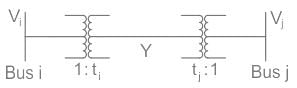
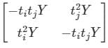
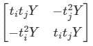
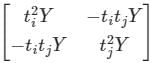
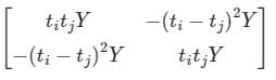
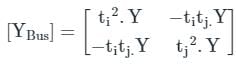
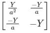
Two buses, i and j, are connected with a transmission line of admittance Y, at the two ends of which there are ideal transformers with turns ratios as shown. Bus admittance matrix for the system is:
- a)
- b)
- c)
- d)
Correct answer is option 'C'. Can you explain this answer?
Two buses, i and j, are connected with a transmission line of admittance Y, at the two ends of which there are ideal transformers with turns ratios as shown. Bus admittance matrix for the system is:
a)
b)
c)
d)
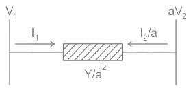
| | Pooja Patel answered |
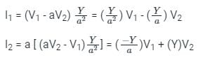
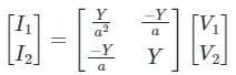
Bus admittance matrix:
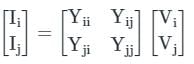
Two buses, i and j, are connected with a transmission line of admittance Y, at the two ends of which there are ideal transformers with turns ratios 1 : ti &1 : tj.
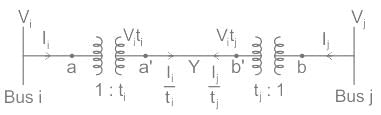
From the circuit shown above,
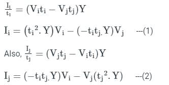
From equation (1) and (2), we get,
Two buses, i and j, are connected with a transmission line of admittance Y, at the two ends of which there are ideal transformers with turns ratios 1 : ti &1 : tj.
From the circuit shown above,
From equation (1) and (2), we get,
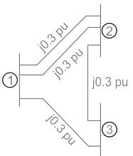
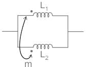
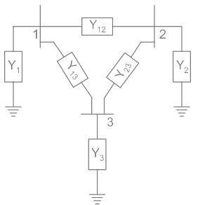
The 3-bus system is shown in the figure, Two lines are connected between bus 1 and bus 2 is having a mutual effect of M = j0.01(additive). Find the Y22 element of the YBus matrix of the system.
- a)-j 9.78 pu
- b)-j 10.58 pu
- c)-j 3.48 pu
- d)-j 8.33 pu
Correct answer is option 'A'. Can you explain this answer?
The 3-bus system is shown in the figure, Two lines are connected between bus 1 and bus 2 is having a mutual effect of M = j0.01(additive). Find the Y22 element of the YBus matrix of the system.
a)
-j 9.78 pu
b)
-j 10.58 pu
c)
-j 3.48 pu
d)
-j 8.33 pu
| | Pooja Patel answered |
Concept:
When two inductances are connected in parallel and have a mutual effect then equivalent inductance can be calculated with the help of the following formula
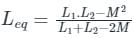
First of all, calculate the equivalent reactance of two-line connected between buses 1 and 2
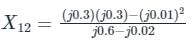
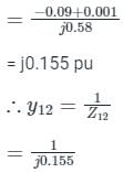
= -j6.45
and

=-j3.33 pu
∴ Y22 = y12 + y23
= -j6.45 + (-j3.33)
=-j9.78 pu.
When two inductances are connected in parallel and have a mutual effect then equivalent inductance can be calculated with the help of the following formula
First of all, calculate the equivalent reactance of two-line connected between buses 1 and 2
= -j6.45
and
=-j3.33 pu
∴ Y22 = y12 + y23
= -j6.45 + (-j3.33)
=-j9.78 pu.
In an n-bus power system, considering n-nodes network, the size of ybus is- a)(n - 1) × (n - 1)
- b)(n + 1) × (n + 1)
- c)n × n
- d)2n × 2n
Correct answer is option 'C'. Can you explain this answer?
In an n-bus power system, considering n-nodes network, the size of ybus is
a)
(n - 1) × (n - 1)
b)
(n + 1) × (n + 1)
c)
n × n
d)
2n × 2n
| | Rajesh Verma answered |
The size of ybus in an n-bus power system is n x n.
Which of the following buses is also known as P-Q bus ?- a)Swing bus
- b)Slack bus
- c)Generation bus or voltage control bus
- d)Load bus
Correct answer is option 'D'. Can you explain this answer?
Which of the following buses is also known as P-Q bus ?
a)
Swing bus
b)
Slack bus
c)
Generation bus or voltage control bus
d)
Load bus
| | Kalyan Patel answered |
Identification of P-Q bus
The bus known as P-Q bus in power system analysis is the load bus. The load bus is also referred to as the P-Q bus because it is responsible for supplying the active power (P) and reactive power (Q) demands of the system.
Explanation
In power system analysis, the load bus represents the buses where the active and reactive power demands are specified. These buses are typically connected to various loads such as residential, commercial, and industrial consumers. The load bus is characterized by having known values of active and reactive power injections.
The load bus is an essential component of power flow analysis and is used to determine the steady-state operating conditions of a power system. By specifying the active and reactive power demands at the load buses, the power flow equations can be solved to obtain the voltage magnitudes and angles at all buses in the system.
Key Points:
- The load bus is also known as the P-Q bus.
- It represents the buses where the active and reactive power demands are specified.
- It is responsible for supplying the active power (P) and reactive power (Q) demands of the system.
Conclusion
In power system analysis, the load bus is referred to as the P-Q bus because it is responsible for supplying the active power (P) and reactive power (Q) demands of the system. The load bus represents the buses where the active and reactive power demands are specified, and it is an essential component in power flow analysis.
A 500 × 500 bus admittance matrix for an electric power system 4000 non-zero elements the minimum number of branches in this system are –
Correct answer is '1750'. Can you explain this answer?
A 500 × 500 bus admittance matrix for an electric power system 4000 non-zero elements the minimum number of branches in this system are –
| | Pooja Patel answered |
No. of non-zero elements = no. of diagonal element + 2 (no. of line)
4000 = 500 + 2 (lines)
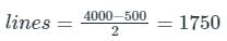
4000 = 500 + 2 (lines)
A bus-bar is rated by-- a)Current only
- b)Current and voltage only
- c)Current, voltage and frequency only
- d)Current, voltage, frequency and short time current capacity
Correct answer is option 'D'. Can you explain this answer?
A bus-bar is rated by-
a)
Current only
b)
Current and voltage only
c)
Current, voltage and frequency only
d)
Current, voltage, frequency and short time current capacity
| | Disha Das answered |
Understanding Bus-Bar Ratings
A bus-bar is a crucial component in electrical systems, serving as a conductor that distributes electrical power. Its rating ensures safe and efficient operation.
Factors Influencing Bus-Bar Ratings
A bus-bar's rating is determined by several key factors:
Current Capacity
- The primary function of a bus-bar is to conduct electricity.
- Current ratings indicate the maximum continuous current the bus-bar can handle without overheating.
Voltage Rating
- Voltage ratings signify the maximum voltage the bus-bar can withstand.
- This is vital to prevent electrical breakdown and ensure safety in the system.
Frequency Considerations
- Frequency indicates the operational cycles per second of the electrical signal.
- Bus-bars must be rated for the frequency of the system, especially in AC applications, to avoid resonance and inefficiencies.
Short Time Current Capacity
- This rating refers to the bus-bar's ability to withstand high currents for short durations, typically during fault conditions.
- It is essential for protecting equipment during faults and ensuring that the bus-bar does not suffer damage.
Conclusion
In conclusion, a bus-bar is rated based on multiple criteria, including current, voltage, frequency, and short time current capacity. This comprehensive rating ensures the bus-bar can safely handle the electrical loads and conditions it will encounter in operation. Understanding these ratings is crucial for engineers to design reliable and safe electrical systems.
A 1000 × 1000 bus admittance matrix for an electric power system has 8000 non-zero elements. The minimum number of branches (transmission lines and transformers) in this system are _____ (up to 2 decimal places).
Correct answer is '3500'. Can you explain this answer?
A 1000 × 1000 bus admittance matrix for an electric power system has 8000 non-zero elements. The minimum number of branches (transmission lines and transformers) in this system are _____ (up to 2 decimal places).
| | Prasad Saini answered |
A 1000 could refer to several different things. Without further context, it is difficult to determine the exact meaning. Some possibilities include:
- A quantity or amount of something. For example, "I have a 1000 dollars" or "There are a 1000 people attending the event."
- A number. In this case, "a 1000" is simply referring to the number 1000.
- A measurement of length, such as 1000 feet or 1000 meters.
- A time, such as 10:00. In some regions, people may refer to 10:00 as "a 1000" using the 24-hour clock system.
Again, without more information, it is difficult to determine the exact meaning of "a 1000."
For the set of linear equations given below, what is the value of voltage V1 after first iteration of Gauss Siedal method? Assume the initial approximation is V1 = 0
10V1 + 2V2 = 10, 4V1 + 7V2 = 15- a)1
- b)0.5714
- c)0.5
- d)0.6367
Correct answer is option 'A'. Can you explain this answer?
For the set of linear equations given below, what is the value of voltage V1 after first iteration of Gauss Siedal method? Assume the initial approximation is V1 = 0
10V1 + 2V2 = 10, 4V1 + 7V2 = 15
10V1 + 2V2 = 10, 4V1 + 7V2 = 15
a)
1
b)
0.5714
c)
0.5
d)
0.6367
| | Pooja Patel answered |
The given equations can be written as
10V1 + 2V2 = 10
⇒ V1 = 1/10 [10 − 2V2]
4V1 + 7V2 = 15
⇒ V2 = 1/7 [15 − 4V1]
Iteration 1:
Put V2 = 0
⇒ V1 = 1/10 [10 − 0] = 1
10V1 + 2V2 = 10
⇒ V1 = 1/10 [10 − 2V2]
4V1 + 7V2 = 15
⇒ V2 = 1/7 [15 − 4V1]
Iteration 1:
Put V2 = 0
⇒ V1 = 1/10 [10 − 0] = 1
In a load flow problem solved by Newton-Raphson method with polar coordinates, the size of the Jacobian is 100 × 100. If there are 20 PV buses in addition to PQ Buses and a slack bus, the total number of buses in the system is _________.
Correct answer is '61'. Can you explain this answer?
In a load flow problem solved by Newton-Raphson method with polar coordinates, the size of the Jacobian is 100 × 100. If there are 20 PV buses in addition to PQ Buses and a slack bus, the total number of buses in the system is _________.
| | Pooja Patel answered |
Size of Jacobian matrix = (2n – m – 2) × (2n – m - 2)
Where n = number of buses
m = number of pv buses
Given that,
Size of Jacobian matrix = 100 × 100
Number of PV buses (m) = 20
⇒ (2n – m - 2) = 100
⇒ 2n – 20 – 2 = 100
⇒ n = 61
Where n = number of buses
m = number of pv buses
Given that,
Size of Jacobian matrix = 100 × 100
Number of PV buses (m) = 20
⇒ (2n – m - 2) = 100
⇒ 2n – 20 – 2 = 100
⇒ n = 61
The slack bus has to be a- a)PV bus
- b)PQ bus
- c)QV bus
- d)No constraint
Correct answer is option 'A'. Can you explain this answer?
The slack bus has to be a
a)
PV bus
b)
PQ bus
c)
QV bus
d)
No constraint
| | Arpita Banerjee answered |
Out of the 15% of Generator buses in a power system, one bus is taken as a slack bus which take care of losses occuring in the system. At a generator bus P and V are known. Hence, a slack bus can be a PV bus.
In comparison to Gauss Seidel, Newton Raphson method takes- a)Less no of iteration and more time per iteration
- b)Less no of iteration and less time per iteration
- c)More no of iteration and more time per iteration
- d)More no of iteration and less time per iteration
- e)None
Correct answer is option 'A'. Can you explain this answer?
In comparison to Gauss Seidel, Newton Raphson method takes
a)
Less no of iteration and more time per iteration
b)
Less no of iteration and less time per iteration
c)
More no of iteration and more time per iteration
d)
More no of iteration and less time per iteration
e)
None
| | Pooja Patel answered |
- Newton Raphson method has more computation time per iteration as compared to the Gauss Siedel method.
- Only the Gauss Siedel method has a problem in convergence for a system with long radial lines.
Newton Raphson method is used to solve- a)linear differential equations
- b)Linear algebraic equations
- c)Non-linear differential equations
- d)non-linear algebraic equations
Correct answer is option 'D'. Can you explain this answer?
Newton Raphson method is used to solve
a)
linear differential equations
b)
Linear algebraic equations
c)
Non-linear differential equations
d)
non-linear algebraic equations
| | Debanshi Nair answered |
Understanding the Newton-Raphson Method
The Newton-Raphson method is a powerful numerical technique used primarily for finding approximate solutions to equations. It is particularly effective for non-linear algebraic equations.
Application of the Newton-Raphson Method
- The method is based on the idea of linear approximation.
- It uses an iterative approach to refine guesses of the roots of a function.
- Starting with an initial guess, the method calculates the tangent line at that point and finds where it intersects the x-axis, providing a better approximation of the root.
Why Non-linear Algebraic Equations?
- Non-linear algebraic equations often do not have straightforward solutions, making analytical methods challenging.
- The Newton-Raphson method excels in these cases because it can handle functions that are not linear, providing quick convergence to a solution.
Key Features of the Method
- Convergence Speed: The method can achieve quadratic convergence, meaning that the number of correct digits roughly doubles with each iteration, making it very efficient.
- Initial Guess Sensitivity: The choice of the initial guess is crucial. A poor choice can lead to divergence or convergence to the wrong root.
- Derivative Requirement: The method requires the derivative of the function, which can be a limitation if the derivative is difficult to compute.
Conclusion
In summary, the Newton-Raphson method is specifically designed for solving non-linear algebraic equations due to its iterative nature and efficiency. Its ability to quickly approximate solutions makes it a valuable tool in fields such as electrical engineering.
A power system has 200 buses of which 150 buses are load buses and others are generator buses. The size of the jacobian matrix is:
Correct answer is '349'. Can you explain this answer?
A power system has 200 buses of which 150 buses are load buses and others are generator buses. The size of the jacobian matrix is:
| | Mahesh Singh answered |
Calculating the size of Jacobian Matrix for a Power System
The Jacobian matrix is used in power system analysis to determine the power flow equations. The size of the Jacobian matrix is determined by the number of buses in the power system. Here's how to calculate the size of the Jacobian matrix for a power system with 200 buses, of which 150 buses are load buses and the others are generator buses.
Count the total number of buses in the power system
- In this case, the total number of buses is 200.
Count the number of generator buses in the power system
- As we know that the total number of buses is 200, and 150 buses are load buses. So the number of generator buses will be 200 - 150 = 50.
Count the number of unknown variables in the power system
- The number of unknown variables is equal to the number of generator buses plus the number of voltage-controlled buses.
- In this case, since there is no mention of voltage-controlled buses, we assume that all buses are PQ buses. Therefore, the number of unknown variables is equal to the number of generator buses, which is 50.
Calculate the size of the Jacobian matrix
- The size of the Jacobian matrix is equal to twice the number of buses, minus the number of unknown variables.
- In this case, the size of the Jacobian matrix will be 2 x 200 - 50 = 350.
- However, we should note that the Jacobian matrix is always square, so we need to take the smaller of the two dimensions. Therefore, the size of the Jacobian matrix is 349.
Conclusion
In conclusion, the size of the Jacobian matrix for a power system with 200 buses, of which 150 buses are load buses and the others are generator buses, is 349.
Assumption of decoupling is valid only if- a)XLine < RLine
- b)XLine = RLine
- c)Any conditon
- d)RLine >> XLine
Correct answer is option 'D'. Can you explain this answer?
Assumption of decoupling is valid only if
a)
XLine < RLine
b)
XLine = RLine
c)
Any conditon
d)
RLine >> XLine
| | Samarth Khanna answered |
Assumption of decoupling is valid in load flow study only if resistance of the line is negligible in comparison to the reactance of the line.
In G - S method of power flow problem, the number of iterations- a)depends on no of buses
- b)depends on tolerance
- c)depends on voltage control buses
- d)remains fixed
Correct answer is option 'B'. Can you explain this answer?
In G - S method of power flow problem, the number of iterations
a)
depends on no of buses
b)
depends on tolerance
c)
depends on voltage control buses
d)
remains fixed
| | Bhavana Reddy answered |
The G - S method of power flow problem
The Gauss-Seidel (G-S) method is an iterative algorithm used to solve power flow problems in electrical power systems. It is widely used due to its simplicity and efficiency. The G-S method iteratively calculates the bus voltages and line flows until convergence is achieved.
The number of iterations in G-S method
The number of iterations required in the G-S method depends on the tolerance level set for convergence. The tolerance level determines the acceptable difference between the calculated values in successive iterations. Once this tolerance level is met, the solution is considered converged, and no further iterations are required.
Dependence on tolerance
The number of iterations in the G-S method depends on the tolerance level set for convergence. A lower tolerance level means a higher accuracy requirement, which may require more iterations to achieve. Conversely, a higher tolerance level allows for less accurate solutions and may require fewer iterations.
The G-S method checks the convergence criterion after each iteration. If the calculated values in successive iterations differ by less than the specified tolerance level, the algorithm stops iterating. Therefore, the number of iterations needed is directly related to the specified tolerance level.
Dependence on other factors
The number of iterations in the G-S method is not dependent on the number of buses or the presence of voltage control buses. These factors affect the complexity and size of the power flow problem but do not directly influence the number of iterations required for convergence.
Conclusion
In summary, the number of iterations in the G-S method of power flow problem depends on the tolerance level set for convergence. It is not influenced by the number of buses or the presence of voltage control buses. By adjusting the tolerance level, the trade-off between accuracy and computational efficiency can be controlled.
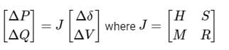
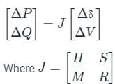
Consider a power system consisting of N number of buses. Buses in this power system are categorized into slack bus, PV buses and PQ buses for load flow study. The number of PQ buses is NL. The balanced Newton-Raphson method is used to carry out load flow study in polar form. H, S, M, and R are sub-matrices of the Jacobian matrix J as shown below:
The dimension of the sub-matrix M is- a)(N - 1) × (N - 1 NL)
- b)NL × (N - 1 + NL)
- c)(N - 1) × (N - 1 + NL)
- d)NL × (N - 1)
Correct answer is option 'D'. Can you explain this answer?
Consider a power system consisting of N number of buses. Buses in this power system are categorized into slack bus, PV buses and PQ buses for load flow study. The number of PQ buses is NL. The balanced Newton-Raphson method is used to carry out load flow study in polar form. H, S, M, and R are sub-matrices of the Jacobian matrix J as shown below:
The dimension of the sub-matrix M is
The dimension of the sub-matrix M is
a)
(N - 1) × (N - 1 NL)
b)
NL × (N - 1 + NL)
c)
(N - 1) × (N - 1 + NL)
d)
NL × (N - 1)
| | Naroj Boda answered |
Number of buses in the system = N
Number of PQ buses = NL
Number of slack buses = 1
Number of PV buses = N - 1 - NL
Newton Raphson method for load flow study in polar form
Number of PQ buses = NL
Number of slack buses = 1
Number of PV buses = N - 1 - NL
Newton Raphson method for load flow study in polar form
The submatrix M relates between [ΔQ] and [Δδ]
Number of elements in ΔQ vector = Number of known Q
Number of elements in ΔQ vector = Number of PQ buses = NL
Number of elements in Δδ vector = Number of unknown δ = N - 1
Size of matrix M = NL × (N - 1)
Size of other sub-matrix:
H = (N - 1) × (N - 1)
S = (N - 1) × NL
R = NL × NL
Number of elements in ΔQ vector = Number of known Q
Number of elements in ΔQ vector = Number of PQ buses = NL
Number of elements in Δδ vector = Number of unknown δ = N - 1
Size of matrix M = NL × (N - 1)
Size of other sub-matrix:
H = (N - 1) × (N - 1)
S = (N - 1) × NL
R = NL × NL
In a load flow solution Vi = 1.083∠150 pu and Vk = 0.986∠-20 pu. What is the direction of active power (P) and reactive power (Q) flow in the line i - k?- a)P and Q flow from i to k
- b)P flows from i to k and Q flows from k to i
- c)Both flow from k t o i
- d)Data is insufficient to determine direction
Correct answer is option 'A'. Can you explain this answer?
In a load flow solution Vi = 1.083∠150 pu and Vk = 0.986∠-20 pu. What is the direction of active power (P) and reactive power (Q) flow in the line i - k?
a)
P and Q flow from i to k
b)
P flows from i to k and Q flows from k to i
c)
Both flow from k t o i
d)
Data is insufficient to determine direction
| | Mihir Khanna answered |
Since active power flows from leading bus to lagging bus therefore, P will flow from i to k.
Since, reactive power flows from high potential bus to low potential bus therefore, Q will flow from i to k.
Since, reactive power flows from high potential bus to low potential bus therefore, Q will flow from i to k.
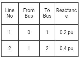
The line reactances of a power network are as follows:
The bus impedance matrix with ‘0’ as reference bus is- a)

- b)

- c)

- d)

Correct answer is option 'C'. Can you explain this answer?
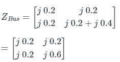
The line reactances of a power network are as follows:
The bus impedance matrix with ‘0’ as reference bus is
The bus impedance matrix with ‘0’ as reference bus is
a)
b)
c)
d)
| | Pooja Patel answered |
By considering line - 1,
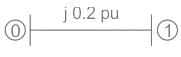
Here ZBUS is formed between new bus & reference bus, so type - 1 formation
∴ ZBus = [j 0.2]
By adding line - 2 to the above Bus
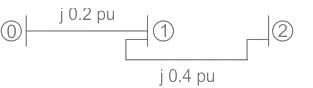
Here ZBUS is formed between new bus & old bus, so type - 2 formation
Here ZBUS is formed between new bus & reference bus, so type - 1 formation
∴ ZBus = [j 0.2]
By adding line - 2 to the above Bus
Here ZBUS is formed between new bus & old bus, so type - 2 formation
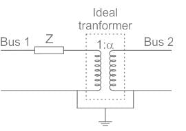
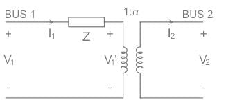
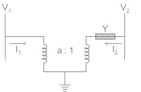
Calculate the [Y]Bus matrix of the given two bus systems.
- a)

- b)
- c)

- d)

Correct answer is option 'D'. Can you explain this answer?
Calculate the [Y]Bus matrix of the given two bus systems.
a)
b)
c)
d)
| | Pooja Patel answered |
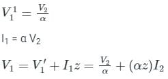
In order to solve such questions where the transformer is connected between the bus and you have to calculate the [Y]Bus matrix, then refer the whole circuit to one side with the help of the transformation ratio of the transformer.
Expression of the current is given by:
Above two expressions are written in the matrix form like below.
Expression of the current is given by:
Above two expressions are written in the matrix form like below.
Which one of the following statement is normally correct for a Z bus matrix?- a)Null matrix
- b)Sparse matrix
- c)Full matrix
- d)Unity matrix
Correct answer is option 'C'. Can you explain this answer?
Which one of the following statement is normally correct for a Z bus matrix?
a)
Null matrix
b)
Sparse matrix
c)
Full matrix
d)
Unity matrix
| | Pooja Patel answered |
Z bus matrix:
- The Z bus matrix or Bus impedance matrix is an important tool for the fault analysis of the power system.
- Z bus matrix can be formed by either inverting the Y bus matrix or by the Z bus building algorithm.
- The diagonal elements of the Z bus are referred to as driving point impedances of the buses and the off-diagonal elements are called transfer impedances.
- The impedance between two far-away buses becomes very large, so there are no zero elements.
- As most of the elements in the Z bus matrix are non zero elements, hence Z bus matrix usually considered as a full matrix or dense matrix.
- The Z bus matrix is also a symmetric matrix.
- Z bus matrix is not preferred for load flow analysis since it requires more time to compute when the number of buses are more than three, and also more memory is required.
Y bus matrix:
- The Y bus or admittance matrix is the most preferred tool for the load flow analysis of the power systems.
- Y bus represents the nodal admittance of the buses in a power system, so it is also called a nodal admittance matrix.
- The admittance between two far-away buses becomes negligible, so most of the elements are zero.
- More than 80% of elements of the Y bus matrix are zero, hence it can be considered as a sparse matrix.
- The Y bus matrix is also a symmetric matrix.
- As most of the elements are zero, the computational time and memory required for load flow analysis are low.
A power system has 100 buses including 10 generator buses. For the load flow analysis using Newton-Raphson method in polar coordinates, the size of the Jacobian is- a)189 × 189
- b)100 × 100
- c)90 × 90
- d)180 × 180
Correct answer is option 'A'. Can you explain this answer?
A power system has 100 buses including 10 generator buses. For the load flow analysis using Newton-Raphson method in polar coordinates, the size of the Jacobian is
a)
189 × 189
b)
100 × 100
c)
90 × 90
d)
180 × 180
| | Zoya Sharma answered |
Number of buses (n) = 100
Generator busses (m) = 10
Order of Jacobian matrix =(2n − 1 − m) × (2n − 1 − m)
= (200 − 1 − 10) × (200 − 1 − 10)
= 189 × 189
Generator busses (m) = 10
Order of Jacobian matrix =(2n − 1 − m) × (2n − 1 − m)
= (200 − 1 − 10) × (200 − 1 − 10)
= 189 × 189
In Gauss Seidel method of power flow problem the number of iterations may be reduced if the correction in voltage at each bus is multiplied by- a)Gauss constant
- b)Acceleration factor
- c)Declaration constant
- d)Blocking factor
Correct answer is option 'B'. Can you explain this answer?
In Gauss Seidel method of power flow problem the number of iterations may be reduced if the correction in voltage at each bus is multiplied by
a)
Gauss constant
b)
Acceleration factor
c)
Declaration constant
d)
Blocking factor
| | Pooja Patel answered |
Gauss Seidel method:
- Gauss-Seidel method of power flow problem is an iterative method used to solve a system of linear equations.
- This method is very simple and uses digital computers for computing.
- In this method as we are using simple algebraical equations so that the calculation time for each iteration is less.
Disadvantages:
- Though it can be applied to any matrix with non zero diagonal elements, the convergence is guaranteed if the matrix is either strictly diagonally dominant or symmetric and positive definite.
- More number of iterations are required so that it has slow convergence.
- Initial approximate guessing value is required for convergence.
- The choice of slack bus affects convergence.
- It is not applicable to the large power system networks.
- It requires an accelerating factor for convergence. The accelerating factor is used for reducing the number of iterations in the Gauss-Seidel method by multplying voltage at each bus with the acceleration factor.
- The value of the accelerating factor is around 1.6 to 1.8.
The Gauss Seidel load flow method has following disadvantages. Mark the incorrect statement- a)Unreliable convergence
- b)Slow convergence
- c)Choice of slack bus affects convergence
- d)A good initial guess for voltages is essential for convergence
- e)All of the above
Correct answer is option 'A'. Can you explain this answer?
The Gauss Seidel load flow method has following disadvantages. Mark the incorrect statement
a)
Unreliable convergence
b)
Slow convergence
c)
Choice of slack bus affects convergence
d)
A good initial guess for voltages is essential for convergence
e)
All of the above
| | Pooja Patel answered |
Gauss Seidel method:
- Gauss-Seidel method of power flow problem is an iterative method used to solve a system of linear equations.
- This method is very simple and uses digital computers for computing.
- In this method as we are using simple algebraical equations so that the calculation time for each iteration is less.
Disadvantages:
- Though it can be applied to any matrix with non zero diagonal elements, the convergence is guaranteed if the matrix is either strictly diagonally dominant or symmetric and positive definite.
- More number of iterations are required so that it has slow convergence.
- Initial approximate guessing value is required for convergence.
- The choice of slack bus affects convergence.
- It is not applicable to the large power system networks.
- It requires an accelerating factor for convergence. The accelerating factor is used for reducing the number of iterations in the Gauss-Seidel method by multplying voltage at each bus with the acceleration factor.
- The value of the accelerating factor is around 1.6 to 1.8.
The load-flow solution is always assured in case of- a)Newton-Raphson method
- b)Gauss-Seidel method
- c)Fast Decoupled method
- d)None of these methods guarantee
Correct answer is option 'A'. Can you explain this answer?
The load-flow solution is always assured in case of
a)
Newton-Raphson method
b)
Gauss-Seidel method
c)
Fast Decoupled method
d)
None of these methods guarantee
| | Pooja Patel answered |
Difference between the Gauss-Seidel method and Newton-Raphson method:
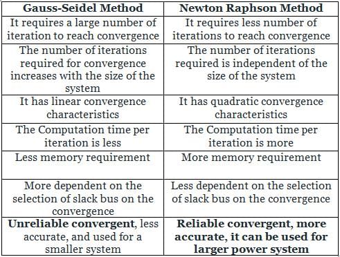
As accuracy is more Newton-Raphson method have assured load flow solution
As accuracy is more Newton-Raphson method have assured load flow solution
A 3 – bus power system network consists of 3 transmission lines. The bus admittance matrix of the uncompensated system is
If the shunt capacitance of all transmission lines is 50% compensated, the imaginary part of the 3rd row 3rd column element (in pu) of the bus admittance matrix after compensation is- a)-j7.0
- b)-j8.5
- c)-j7.5
- d)-j9.0
Correct answer is option 'B'. Can you explain this answer?
A 3 – bus power system network consists of 3 transmission lines. The bus admittance matrix of the uncompensated system is
If the shunt capacitance of all transmission lines is 50% compensated, the imaginary part of the 3rd row 3rd column element (in pu) of the bus admittance matrix after compensation is
If the shunt capacitance of all transmission lines is 50% compensated, the imaginary part of the 3rd row 3rd column element (in pu) of the bus admittance matrix after compensation is
a)
-j7.0
b)
-j8.5
c)
-j7.5
d)
-j9.0
 | Cstoppers Instructors answered |
Concept:
For a 3 bus power system
For the above figure, the admittance matrix is as shown below.
Diagonal elements of the Bus Admittance matrix are known as self-admittances and the off-diagonal elements are known as mutual admittances.
Calculation:
Given bus admittance matrix of the uncompensated line is
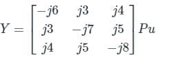
By comparing the above matrix with standard 3 bus matrix
y13 = -j4
y32 = -j5
⇒ y31 + y32 + y33 = -j8
⇒ y33 = j
After compensating,
y33 = j/2
Y33(new) = -8.5 j.
For a 3 bus power system
For the above figure, the admittance matrix is as shown below.
Diagonal elements of the Bus Admittance matrix are known as self-admittances and the off-diagonal elements are known as mutual admittances.
Calculation:
Given bus admittance matrix of the uncompensated line is
By comparing the above matrix with standard 3 bus matrix
y13 = -j4
y32 = -j5
⇒ y31 + y32 + y33 = -j8
⇒ y33 = j
After compensating,
y33 = j/2
Y33(new) = -8.5 j.
Which of the following has a problem in convergence for a system with long radial lines?- a)Newton-Raphson
- b)Gauss-Seidel
- c)Both Newton-Raphson and Gauss Siedel
- d)None of the two methods
Correct answer is option 'B'. Can you explain this answer?
Which of the following has a problem in convergence for a system with long radial lines?
a)
Newton-Raphson
b)
Gauss-Seidel
c)
Both Newton-Raphson and Gauss Siedel
d)
None of the two methods
| | Nishtha Chauhan answered |
Explanation:
Gauss-Seidel Method:
The Gauss-Seidel method is an iterative technique used to solve a system of linear equations. In this method, the system is solved one variable at a time, using the most recent values of the other variables.
When dealing with systems that have long radial lines, the Gauss-Seidel method can encounter convergence issues. This is because the method relies on the values of neighboring variables to update the current variable. In systems with long radial lines, the influence of neighboring variables may not propagate quickly enough, leading to slow convergence or even divergence.
Therefore, the Gauss-Seidel method may have problems with convergence for systems with long radial lines.
Newton-Raphson Method:
The Newton-Raphson method is a root-finding algorithm that can also be used to solve systems of nonlinear equations. This method involves linearizing the system of equations and iteratively updating the solution until convergence is achieved.
Unlike the Gauss-Seidel method, the Newton-Raphson method does not rely on neighboring variables for updating a particular variable. Instead, it uses the Jacobian matrix to calculate the direction and magnitude of the update. Therefore, the Newton-Raphson method is not as sensitive to the spatial arrangement of variables in the system.
In conclusion, the Gauss-Seidel method is more likely to encounter convergence issues for systems with long radial lines compared to the Newton-Raphson method.
In a 100 bus power system, there are 10 generators. In a particular iteration of Newton Raphson load flow technique (in polar coordinates), two of the PV buses are converted to PQ type. In this iteration,- a)the number of unknown voltage angles increases by two and the number of unknown voltage magnitudes increases by two.
- b)the number of unknown voltage angles remains unchanged and the number of unknown voltage magnitudes increases by two.
- c)the number of unknown voltage angles increases by two and the number of unknown voltage magnitudes decreases by two.
- d)the number of unknown voltage angles remains unchanged and the number of unknown voltage magnitudes decreases by two.
Correct answer is option 'B'. Can you explain this answer?
In a 100 bus power system, there are 10 generators. In a particular iteration of Newton Raphson load flow technique (in polar coordinates), two of the PV buses are converted to PQ type. In this iteration,
a)
the number of unknown voltage angles increases by two and the number of unknown voltage magnitudes increases by two.
b)
the number of unknown voltage angles remains unchanged and the number of unknown voltage magnitudes increases by two.
c)
the number of unknown voltage angles increases by two and the number of unknown voltage magnitudes decreases by two.
d)
the number of unknown voltage angles remains unchanged and the number of unknown voltage magnitudes decreases by two.
| | Pooja Patel answered |
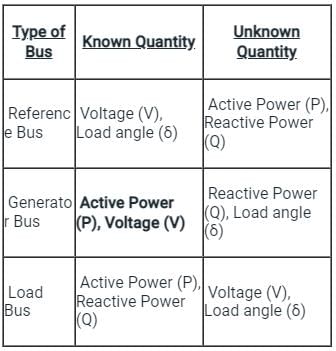
A bus in a power system is a line at which the several components of the power system like generators, loads, and feeders, etc., are connected.
The buses in a power system are associated with four quantities, these quantities are the following:
The magnitude of the voltage
The buses in a power system are associated with four quantities, these quantities are the following:
The magnitude of the voltage
- Phase angle
- Active power
- Reactive power
In the load flow studies, two variable are known, and the other two is to determined.
Depends on the quantity to be specified the buses are classified into three categories as follow:

The table shown below shows the types of buses and the associated known and unknown value.
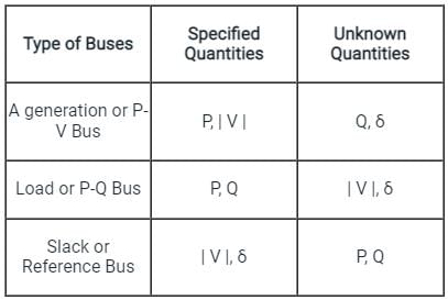
Depends on the quantity to be specified the buses are classified into three categories as follow:
The table shown below shows the types of buses and the associated known and unknown value.
Generation Bus or Voltage Control Bus:
- This bus is also called the P-V bus.
- on this bus, the voltage magnitude corresponding to generate voltage and true or active power P corresponding to its rating are specified.
- Voltage magnitude is maintained constant at a specified value by injection of reactive power.
- The reactive power generation Q and phase angle δ of the voltage is to be computed.
Load Bus:
- This is also called the P-Q bus
- at this bus, the active and reactive power is injected into the network.
- The magnitude and phase angle of the voltage is to be computed.
- Here the active power P and reactive power Q are specified, and the load bus voltage can be permitted within a tolerable value, i.e., 5 %.
- The phase angle of the voltage, i.e.δ is not very important for the load.
Slack, Swing, or Reference Bus:
- Slack bus in a power system absorbs or emits active or reactive power from the power system.
- The slack bus does not carry any load.
- At this bus, the magnitude and phase angle of the voltage is specified.
- The phase angle of the voltage is usually set equal to zero.
For formation of the Y bus matrix (using node voltage analysis) in power system network modelling ______ is used - a)KVL
- b)KCL
- c)Faraday's law
- d)all are correct
Correct answer is option 'B'. Can you explain this answer?
For formation of the Y bus matrix (using node voltage analysis) in power system network modelling ______ is used
a)
KVL
b)
KCL
c)
Faraday's law
d)
all are correct
| | Raj Singh answered |
Introduction:
In power system network modeling, the Y bus matrix is an essential component that represents the admittance between different nodes in the network. It is used for various analysis and calculations, such as load flow studies, fault analysis, and stability analysis. The Y bus matrix is formed using the node voltage analysis method, which is based on Kirchhoff's current law (KCL).
Kirchhoff's Current Law (KCL):
Kirchhoff's Current Law states that the algebraic sum of currents entering and leaving a node in an electrical circuit is zero. It is based on the principle of conservation of charge.
Formation of Y bus matrix:
The Y bus matrix is formed by considering the admittance between different nodes in the power system network. The admittance is the reciprocal of impedance and represents the ease with which current can flow through a particular branch or element.
To form the Y bus matrix using node voltage analysis, the following steps are typically followed:
1. Node numbering: Assign a unique number to each node in the power system network.
2. Formulate the equations: Write the KCL equations for each node in terms of the unknown node voltages. These equations represent the current entering or leaving each node.
3. Admittance representation: Represent the admittance between different nodes in terms of conductance (G) and susceptance (B). The admittance can be determined based on the type of element connecting the nodes. For example, for a resistor, the admittance is G, while for a reactance, the admittance is jB.
4. Construct the Y bus matrix: Based on the KCL equations and admittance representation, construct the Y bus matrix by filling in the appropriate values. The Y bus matrix is a square matrix with dimensions equal to the total number of nodes in the power system network.
5. Include shunt elements: If there are shunt elements such as capacitors or inductors connected to the nodes, include their admittance values in the Y bus matrix as well.
6. Account for grounded nodes: If any nodes in the network are grounded, the corresponding row and column in the Y bus matrix will be zero except for the diagonal element, which represents the total admittance connected to the ground.
7. Finalize the Y bus matrix: Once all the elements and admittances are included, the Y bus matrix is finalized and can be used for various power system analysis.
Conclusion:
In power system network modeling, the Y bus matrix is formed using the node voltage analysis method, which is based on Kirchhoff's current law (KCL). KCL ensures that the algebraic sum of currents entering and leaving a node is zero. By formulating the KCL equations for each node and considering the admittance between different nodes, the Y bus matrix can be constructed. The Y bus matrix is an essential tool for power system analysis and calculations.
Out of the following options, the most relevant information needed to specify the real power (P) at the PV buses in a load flow analysis is- a)solution of economic load dispatch
- b)rated power output of the generator
- c)rated voltage of the generator
- d)base power of the generator
Correct answer is option 'A'. Can you explain this answer?
Out of the following options, the most relevant information needed to specify the real power (P) at the PV buses in a load flow analysis is
a)
solution of economic load dispatch
b)
rated power output of the generator
c)
rated voltage of the generator
d)
base power of the generator
| | Poulomi Ahuja answered |
Importance of Economic Load Dispatch in Determining Real Power at PV Buses
Solution of Economic Load Dispatch
The solution of economic load dispatch is crucial in determining the real power (P) at the PV buses in a load flow analysis. Economic load dispatch involves optimizing the power generation from different sources to meet the load demand at minimum cost while satisfying various constraints. By solving the economic load dispatch problem, the real power output at each generator, including the PV buses, can be determined accurately.
Rated Power Output of the Generator
While the rated power output of the generator is important information, it alone is not sufficient to specify the real power at the PV buses in a load flow analysis. The economic load dispatch solution takes into account various factors such as generator costs, transmission constraints, and system losses, which influence the real power output at the PV buses.
Rated Voltage of the Generator
The rated voltage of the generator is relevant for determining the voltage profile in the system but does not directly specify the real power at the PV buses. The real power output at the PV buses is dependent on the economic dispatch solution, which considers the power output of generators in the system.
Base Power of the Generator
The base power of the generator is used as a reference for system calculations but does not provide specific information about the real power at the PV buses. The economic load dispatch solution is the key factor in determining the real power output at the PV buses in a load flow analysis.
Diagonal elements and off-diagonal elements of the bus admittance matrix are respectively known as- a)self-admittances and mutual admittances
- b)mutual admittances and self-admittances
- c)self-admittances
- d)mutual admittances
Correct answer is option 'A'. Can you explain this answer?
Diagonal elements and off-diagonal elements of the bus admittance matrix are respectively known as
a)
self-admittances and mutual admittances
b)
mutual admittances and self-admittances
c)
self-admittances
d)
mutual admittances
| | Mainak Pillai answered |
Diagonal elements and off-diagonal elements of the bus admittance matrix are respectively known as:
The diagonal elements and off-diagonal elements of the bus admittance matrix in power system analysis are known as self-admittances and mutual admittances, respectively.
Explanation:
In power system analysis, the bus admittance matrix is used to represent the network of interconnected buses in an electrical power system. It is a complex symmetric matrix that describes the electrical relationships between the buses in terms of their admittances.
The diagonal elements of the bus admittance matrix represent the self-admittances of the buses. These elements correspond to the admittance of each individual bus with respect to itself. In other words, they represent the self-impedance or self-admittance of each bus without considering the influence of other buses. The self-admittances are usually given by the sum of the shunt conductances and susceptances connected to each bus.
On the other hand, the off-diagonal elements of the bus admittance matrix represent the mutual admittances between pairs of buses. These elements correspond to the admittance between two different buses in the network. They represent the coupling or interaction between different buses in the system. The mutual admittances are usually given by the sum of the series conductances and susceptances between pairs of buses.
Summary:
To summarize, the diagonal elements of the bus admittance matrix are known as self-admittances because they represent the admittance of each bus with respect to itself. The off-diagonal elements of the bus admittance matrix are known as mutual admittances because they represent the admittance between pairs of different buses in the system.
In a power system with 100 buses, 1 bus is taken as slack bus, 15 buses are P\/ buses and rest are PQ buses. The number of variables to be solved by NR method in polar coordinates is- a)100
- b)198
- c)200
- d)183
Correct answer is option 'D'. Can you explain this answer?
In a power system with 100 buses, 1 bus is taken as slack bus, 15 buses are P\/ buses and rest are PQ buses. The number of variables to be solved by NR method in polar coordinates is
a)
100
b)
198
c)
200
d)
183
| | Ishan Chawla answered |
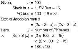
Hence, number of variables to be solved by NR method in polar coordinates = 183.
At generator bus, defined quantities are -- a)|Pg| and |Vg| are defined
- b)|Pd| and |Qd| are defined
- c)|Pg| and |δ| are defined
- d)|Pg| - |Vg| and |δ| are defined
Correct answer is option 'A'. Can you explain this answer?
At generator bus, defined quantities are -
a)
|Pg| and |Vg| are defined
b)
|Pd| and |Qd| are defined
c)
|Pg| and |δ| are defined
d)
|Pg| - |Vg| and |δ| are defined
| | Anshika Nambiar answered |
Understanding Generator Bus Definitions
At a generator bus in power systems, specific electrical quantities are defined to facilitate analysis and control. The correct choice, option 'A', indicates that both active power generation and voltage magnitude are specified.
Key Quantities Defined at Generator Bus:
- |Pg|: This represents the real power output of the generator. It is crucial for ensuring that the power generation meets the demand and maintains system stability.
- |Vg|: This denotes the voltage magnitude at the generator bus. Voltage levels are essential for the proper functioning of electrical equipment and for maintaining system reliability.
Why Other Options Are Not Correct:
- Option B (|Pd| and |Qd|): This option refers to the demand side, where |Pd| is the real power demand and |Qd| is the reactive power demand. While important, these are not defined quantities at the generator bus.
- Option C (|Pg| and |δ|): Here, |δ| refers to the power angle, which is not necessarily defined at the generator bus. |Pg| is relevant, but |δ| alone does not provide a complete picture of the generator's operating conditions.
- Option D (|Pg| - |Vg| and |δ|): This option mixes quantities that are not consistently defined together at the generator bus. The expression |Pg| - |Vg| does not represent a standard definition in this context.
Conclusion:
In summary, option 'A' is correct because it captures the essential quantities necessary for analyzing and managing generator operations in a power system. Understanding these definitions is vital for engineers working in electrical engineering.
In the following network, the voltage magnitudes at all buses are equal to 1 pu, the voltage phase angles are very small, and the line resistances are negligible. All the line reactances are equal to j1Ω
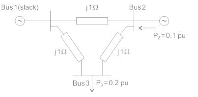
If the base impedance and the line – to line base voltage are 100 ohms and 100 kV respectively, then the real power in MW delivered by the generator connected at the slack bus is- a)-10
- b)0
- c)10
- d)20
Correct answer is option 'C'. Can you explain this answer?
In the following network, the voltage magnitudes at all buses are equal to 1 pu, the voltage phase angles are very small, and the line resistances are negligible. All the line reactances are equal to j1Ω
If the base impedance and the line – to line base voltage are 100 ohms and 100 kV respectively, then the real power in MW delivered by the generator connected at the slack bus is
If the base impedance and the line – to line base voltage are 100 ohms and 100 kV respectively, then the real power in MW delivered by the generator connected at the slack bus is
a)
-10
b)
0
c)
10
d)
20
| | Naroj Boda answered |
Consider the voltage phase angles at buses 2 and 3 be Q2 and Q3 since, all the three buses have the equal voltage magnitude. Which is 1 pu, so, it is a D.C. load flow. The injections at Bus 2 and 3 are respectively P2 = 0.1 Pu
P3 = -0.2 Pu
P1 + P2 + P3 = 0
P1 – P2 – P3 = -0.1 + 0.2 = 0.1 Pu
Now, the apparent power delivered to base is,
The real power delivered by slack bus
P = P1 |S| = (0.1) (100 × 106)
= 10 × 106 watt = 10 MW
P3 = -0.2 Pu
P1 + P2 + P3 = 0
P1 – P2 – P3 = -0.1 + 0.2 = 0.1 Pu
Now, the apparent power delivered to base is,
The real power delivered by slack bus
P = P1 |S| = (0.1) (100 × 106)
= 10 × 106 watt = 10 MW
Providing synchronous condensers at a load bus will control- a)P at bus
- b)Q
- c)p.f.
- d)(b) and (c)
Correct answer is option 'D'. Can you explain this answer?
Providing synchronous condensers at a load bus will control
a)
P at bus
b)
Q
c)
p.f.
d)
(b) and (c)
| | Subham Chaudhary answered |
A synchronous condeser regulates Q and thus controls power factor of the system.
Which method is used as an advanced iterative method for generating appropriate solution steps to a real solution of a given nonlinear equation?- a)Newton Raphson method
- b)Gauss-Seidal method
- c)Fast Decoupled load flow method
- d)Bus admittance matrix
Correct answer is option 'A'. Can you explain this answer?
Which method is used as an advanced iterative method for generating appropriate solution steps to a real solution of a given nonlinear equation?
a)
Newton Raphson method
b)
Gauss-Seidal method
c)
Fast Decoupled load flow method
d)
Bus admittance matrix
| | Pooja Patel answered |
Newton Raphson Method:
- The Newton-Raphson method is an advanced iterative method for generating appropriate solution steps to a real solution of a given nonlinear equation.
- The iterative formula used in the NR method is:
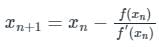
If the reference bus is changed in two load flow runs with same system data and power obtained for reference bus taken as specified P and Q in the latter run- a)The system losses will be unchanged but complex bus voltages will change.
- b)The system losses will change but complex bus voltages remain unchanged.
- c)The system losses as well as complex bus voltage will change.
- d)The system losses as well as complex bus voltage will be unchanged.
Correct answer is option 'A'. Can you explain this answer?
If the reference bus is changed in two load flow runs with same system data and power obtained for reference bus taken as specified P and Q in the latter run
a)
The system losses will be unchanged but complex bus voltages will change.
b)
The system losses will change but complex bus voltages remain unchanged.
c)
The system losses as well as complex bus voltage will change.
d)
The system losses as well as complex bus voltage will be unchanged.
| | Pooja Patel answered |
If the reference bus is changed in two load flow runs with same system data and power obtained for reference bus taken as specified P and Q.
So, the bus is taken as load bus.
So, the loses will be same but the complex bus voltage will change.
So, the bus is taken as load bus.
So, the loses will be same but the complex bus voltage will change.
Chapter doubts & questions for Load Flow Studies - Power Systems 2026 is part of Electrical Engineering (EE) exam preparation. The chapters have been prepared according to the Electrical Engineering (EE) exam syllabus. The Chapter doubts & questions, notes, tests & MCQs are made for Electrical Engineering (EE) 2026 Exam. Find important definitions, questions, notes, meanings, examples, exercises, MCQs and online tests here.
Chapter doubts & questions of Load Flow Studies - Power Systems in English & Hindi are available as part of Electrical Engineering (EE) exam. Download more important topics, notes, lectures and mock test series for Electrical Engineering (EE) Exam by signing up for free.
Power Systems21 videos|112 docs|45 tests |