


All Exams >
Electrical Engineering (EE) >
Power Systems >
All Questions
All questions of Switchgear & Protection for Electrical Engineering (EE) Exam
A three phase transformer having a line voltage ratio of 400/33000 V is connected in the star-delta. The CTs on the 400V side have a CT ratio of 1000/5. What will be the current through the pilot wire?- a)5√3 A
- b)5/√3 A
- c)5 A
- d)1/5 A
Correct answer is option 'A'. Can you explain this answer?
A three phase transformer having a line voltage ratio of 400/33000 V is connected in the star-delta. The CTs on the 400V side have a CT ratio of 1000/5. What will be the current through the pilot wire?
a)
5√3 A
b)
5/√3 A
c)
5 A
d)
1/5 A
|
|
Anuj Rane answered |
The current through the pilot wire can be calculated using the formula:
Ip = (IL1 + IL2 + IL3) / N
where Ip is the current through the pilot wire, IL1, IL2, and IL3 are the line currents on the 400V side, and N is the CT ratio (1000/5).
To calculate the line currents, we can use the formula:
IL = VL / ZL
where IL is the line current, VL is the line voltage, and ZL is the impedance of the load.
Since the transformer is connected in the star-delta, the line voltage on the 400V side is equal to the phase voltage, which is 400V. The impedance of the load is not given, so we cannot calculate the line currents directly.
However, we can use the line voltage ratio to find the phase voltage on the 33 kV side:
Vp = Vs / sqrt(3)
where Vp is the phase voltage on the 33 kV side, and Vs is the line voltage on the 33 kV side. Substituting the given values, we get:
Vp = 33000 / sqrt(3) = 19052.8 V
Now we can use the line voltage ratio to find the line voltage on the 400V side:
VL = Vp / (400/33000) = 247.5 V
Assuming a balanced load, we can calculate the line current on the 400V side:
IL = VL / ZL
Since the impedance is not given, we can assume a value of 1 ohm for simplicity:
IL = 247.5 / 1 = 247.5 A
Finally, we can calculate the current through the pilot wire:
Ip = (IL1 + IL2 + IL3) / N
Since the transformer is connected in the star-delta, the line currents on the 400V side are equal to the phase currents. Therefore:
Ip = (IL + IL + IL) / (1000/5) = 5 A
So the current through the pilot wire is 5 A.
Ip = (IL1 + IL2 + IL3) / N
where Ip is the current through the pilot wire, IL1, IL2, and IL3 are the line currents on the 400V side, and N is the CT ratio (1000/5).
To calculate the line currents, we can use the formula:
IL = VL / ZL
where IL is the line current, VL is the line voltage, and ZL is the impedance of the load.
Since the transformer is connected in the star-delta, the line voltage on the 400V side is equal to the phase voltage, which is 400V. The impedance of the load is not given, so we cannot calculate the line currents directly.
However, we can use the line voltage ratio to find the phase voltage on the 33 kV side:
Vp = Vs / sqrt(3)
where Vp is the phase voltage on the 33 kV side, and Vs is the line voltage on the 33 kV side. Substituting the given values, we get:
Vp = 33000 / sqrt(3) = 19052.8 V
Now we can use the line voltage ratio to find the line voltage on the 400V side:
VL = Vp / (400/33000) = 247.5 V
Assuming a balanced load, we can calculate the line current on the 400V side:
IL = VL / ZL
Since the impedance is not given, we can assume a value of 1 ohm for simplicity:
IL = 247.5 / 1 = 247.5 A
Finally, we can calculate the current through the pilot wire:
Ip = (IL1 + IL2 + IL3) / N
Since the transformer is connected in the star-delta, the line currents on the 400V side are equal to the phase currents. Therefore:
Ip = (IL + IL + IL) / (1000/5) = 5 A
So the current through the pilot wire is 5 A.

Which type of oil has the highest breakdown strength?- a)Cable oil
- b)Silicon oil
- c)Transformer oil
- d)Capacitor oil
Correct answer is option 'B'. Can you explain this answer?
Which type of oil has the highest breakdown strength?
a)
Cable oil
b)
Silicon oil
c)
Transformer oil
d)
Capacitor oil
|
|
Gargi Mishra answered |
Introduction:
The breakdown strength of an insulating oil refers to its ability to withstand electrical stress without experiencing electrical breakdown. It is an important property to consider when selecting an oil for electrical equipment such as transformers, capacitors, and cables.
Explanation:
Among the given options, silicon oil has the highest breakdown strength. Here's why:
Cable Oil:
- Cable oil is specifically formulated for use in power cables to provide insulation and cooling.
- It has good electrical properties but generally has lower breakdown strength compared to other insulating oils.
Transformer Oil:
- Transformer oil is used in electrical transformers to provide insulation and cooling.
- It is highly refined mineral oil with additives to enhance its electrical properties.
- Transformer oil has good breakdown strength, but it is not the highest among the given options.
Capacitor Oil:
- Capacitor oil is used in electrical capacitors to provide insulation and cooling.
- It is similar to transformer oil but may have different additives depending on the specific application.
- Capacitor oil has good breakdown strength, but it is not the highest among the given options.
Silicon Oil:
- Silicon oil, also known as silicone oil, is a synthetic oil composed of silicon atoms.
- It has excellent electrical properties and high breakdown strength, making it suitable for various electrical applications.
- Silicon oil can withstand higher electrical stress before experiencing breakdown compared to other insulating oils.
- It is commonly used in high-voltage equipment, such as high-voltage cables and power transformers.
Conclusion:
In summary, among the given options, silicon oil has the highest breakdown strength. It is preferred for applications where high electrical stress needs to be withstood without experiencing electrical breakdown.
The neutral of the three phase 20 MVA, 11kV alternator is earthed through a resistance of 5 ohms, the relay is set to operate when there is an out of balance current of 1.5 A. The CTs have a ratio of 100/5. What should be the minimum value of the earthing resistance to protect 90% of winding?- a)2.12 Ω
- b)1.12 Ω
- c)4.24 Ω
- d)3.24 Ω
Correct answer is option 'A'. Can you explain this answer?
The neutral of the three phase 20 MVA, 11kV alternator is earthed through a resistance of 5 ohms, the relay is set to operate when there is an out of balance current of 1.5 A. The CTs have a ratio of 100/5. What should be the minimum value of the earthing resistance to protect 90% of winding?
a)
2.12 Ω
b)
1.12 Ω
c)
4.24 Ω
d)
3.24 Ω
|
|
Ritika Sarkar answered |
The minimum value of earthing resistance to protect 90% of winding can be calculated using the following formula:
R = (2/3) × (CT ratio) × (relay setting) × (neutral earthing resistance)
Where,
CT ratio = 100/5 = 20
Relay setting = 1.5 A
Neutral earthing resistance = 5 ohms
Substituting the values in the formula, we get:
R = (2/3) × 20 × 1.5 × 5
R = 40 ohms
Therefore, the minimum value of earthing resistance to protect 90% of winding is 40 ohms.
An ideal circuit breaker should offer- a)Zero & infinite impedance before & after interruption respectively
- b)Infinity & zero impedance before & after interruption respectively
- c)Equal impedance before & after interruption
- d)None of these
Correct answer is option 'A'. Can you explain this answer?
An ideal circuit breaker should offer
a)
Zero & infinite impedance before & after interruption respectively
b)
Infinity & zero impedance before & after interruption respectively
c)
Equal impedance before & after interruption
d)
None of these
|
|
Vibhor Goyal answered |
- A circuit breaker is a switching device that interrupts the abnormal or fault current
- It is a mechanical device that disturbs the flow of high magnitude (fault) current and in additions performs the function of a switch
- The circuit breaker is mainly designed for closing or opening of an electrical circuit, thus protects the electrical system from damage
- When the circuit breaker is closed, it acts as short switch; Thus, before interruption ideal circuit breaker should offer zero impedance
- When the circuit breaker is open, it acts as open switch; Thus, after interruption ideal circuit breaker should offer infinite impedance
Which of the following could be the effect of using high-speed circuit breakers in a power system?- a)Reduced system reliability
- b)Improved system stability
- c)Reduced short circuit current
- d)Increased short circuit current
Correct answer is option 'B'. Can you explain this answer?
Which of the following could be the effect of using high-speed circuit breakers in a power system?
a)
Reduced system reliability
b)
Improved system stability
c)
Reduced short circuit current
d)
Increased short circuit current

|
Machine Experts answered |
Concept:
- The use of high-speed circuit breakers improves the system stability.
- The basic objective is to enable high-speed fault clearing. The amount of kinetic energy gained during acceleration can be reduced by the use of a high-speed circuit breaker.
- Standard practice for high voltage systems is one-cycle relaying and two-cycle circuit breakers allowing the fault clearing after three cycles.
For below 400 KV systems, the circuit breaker is designed to withstand ______above the normal system voltage. - a)10%
- b)20%
- c)30%
- d)40%
Correct answer is option 'A'. Can you explain this answer?
For below 400 KV systems, the circuit breaker is designed to withstand ______above the normal system voltage.
a)
10%
b)
20%
c)
30%
d)
40%
|
|
Aarya Basu answered |
Design of Circuit Breaker for Below 400 KV Systems
The circuit breaker used in below 400 KV systems is designed to withstand a certain percentage above the normal system voltage to ensure reliable operation and safety.
Answer Explanation
Correct Answer: Option 'A' - 10%
Explanation:
- The circuit breaker is designed to withstand a voltage level that is 10% above the normal system voltage.
- This additional capacity allows the circuit breaker to handle voltage fluctuations and transient overvoltages that may occur during normal operation.
- By designing the circuit breaker with a 10% margin above the normal system voltage, it can effectively protect the system and equipment from damage.
- This design feature is crucial in ensuring the reliability and longevity of the electrical system.
Therefore, for below 400 KV systems, the circuit breaker is designed to withstand 10% above the normal system voltage to maintain system integrity and protection.
Pilot relaying schemes are used for protection of- a)bus bars
- b)transformers
- c)transmission lines
- d)instrument transfomers
Correct answer is option 'C'. Can you explain this answer?
Pilot relaying schemes are used for protection of
a)
bus bars
b)
transformers
c)
transmission lines
d)
instrument transfomers
|
|
Anshika Khanna answered |
Pilot relaying schemes provide high speed protection for transmission lines.
The highest rating of Triple pole with Neutral (TPN) MCB main switches available in the local market is _______.- a)126 A
- b)189 A
- c)252 A
- d)63 A
Correct answer is option 'D'. Can you explain this answer?
The highest rating of Triple pole with Neutral (TPN) MCB main switches available in the local market is _______.
a)
126 A
b)
189 A
c)
252 A
d)
63 A

|
Vertex Academy answered |
A triple pole with a Neutral (TPN) Miniature Circuit Breaker:
- It is used to protect the circuits from short circuit faults. It is used in the place of the fuse.
- When the amount of electricity is increasing in wire, the MCB turns off and the result is it breaks the circuit.
- It prevents from burning of home appliances.
- The current rating of single-pole Triple pole with Neutral (TPN) MCB main switches available in the local market is 63 A.
Additional Information
A miniature circuit breaker (MCB):
- It automatically switches off the power supply during overload and faults.
- This function of automatic switching is accomplished by a bimetallic strip.
- Whenever continuous overcurrent flows through MCB, the bimetallic strip is heated and deflects by bending.
- This deflection of the bimetallic strip releases a mechanical latch.
- As this mechanical latch is attached to the operating mechanism, it causes to open the miniature circuit breaker contacts, and the MCB turns off thereby stopping the current to flow in the circuit.
The voltage that appears across the breaker contact after the circuit breaker is opened is called.- a)Arc voltage
- b)Restriking voltage
- c)Recovery voltage
- d)Surge voltage
Correct answer is option 'C'. Can you explain this answer?
The voltage that appears across the breaker contact after the circuit breaker is opened is called.
a)
Arc voltage
b)
Restriking voltage
c)
Recovery voltage
d)
Surge voltage
|
|
Machine Experts answered |
Recovery Voltage:
The RMS voltage that appears across the circuit breaker contacts after final arc interruption (when breaker opens) is called “recovery voltage”
Restriking Voltage:
It may be defined as the voltages that appears across the breaking contact at the instant of arc extinction
Active Recovery Voltage:
It may be defined as the instantaneous recovery voltage at the instant of arc extinction
Arc Voltage:
It may be defined as the voltages that appears across the contact during the arcing period, when the current flow is maintained in the form of an arc. It assumes low value except for the point at which the voltage rises rapidly to a peak value and current reaches to zero.
There is a problem of high transient over voltages while interrupting- a)capacitive currents
- b)inductive currents
- c)heavy short circuit current
- d)(a) or (c)
Correct answer is option 'A'. Can you explain this answer?
There is a problem of high transient over voltages while interrupting
a)
capacitive currents
b)
inductive currents
c)
heavy short circuit current
d)
(a) or (c)
|
|
Palak Verma answered |
High transient over voltages occurs in power system due to formation of capacitance across the breaker poles. These are also called switching over voltages.
A three phase transformer having a line voltage ratio of 400/33000 V is connected in the star-delta. The CTs on the 400V side have a CT ratio of 1000/5. What must be the ratio of CTs on the 33000 side?- a)7/5
- b)5/7
- c)3/5
- d)5/2
Correct answer is option 'A'. Can you explain this answer?
A three phase transformer having a line voltage ratio of 400/33000 V is connected in the star-delta. The CTs on the 400V side have a CT ratio of 1000/5. What must be the ratio of CTs on the 33000 side?
a)
7/5
b)
5/7
c)
3/5
d)
5/2
|
|
Anoushka Choudhury answered |
Given information:
- Line voltage ratio of the three-phase transformer: 400/33000 V
- CT ratio on the 400V side: 1000/5
To find: The ratio of CTs on the 33000V side
Solution:
1. The line voltage ratio of the transformer is given as 400/33000 V. This means that the primary side (400V) is connected in star configuration, and the secondary side (33000V) is connected in delta configuration.
2. The CT ratio on the 400V side is given as 1000/5. This means that the primary CT has a ratio of 1000/5, i.e., for every 1000A primary current, the secondary current is 5A.
3. In a star-delta transformer connection, the line current on the primary side is √3 times the phase current. Similarly, the line current on the secondary side is √3 times the phase current.
4. Since the primary CT ratio is given, we can calculate the primary line current using the formula:
Primary Line Current = Primary CT Ratio * Secondary Line Current
Here, the secondary line current is the same as the secondary phase current since it is a delta configuration.
So, Primary Line Current = 1000/5 * Secondary Phase Current
5. The secondary phase current can be calculated using the formula:
Secondary Phase Current = Secondary Line Voltage / (√3 * Secondary Line Impedance)
In a delta-connected transformer, the line impedance is equal to the phase impedance.
6. The secondary line voltage is given as 33000V, and the secondary line impedance can be calculated using the formula:
Secondary Line Impedance = Secondary Line Voltage / Secondary Line Current
7. Substitute the given values into the formulas to calculate the primary line current:
Secondary Line Impedance = 33000V / (√3 * Secondary Line Current)
Primary Line Current = 1000/5 * (√3 * Secondary Line Impedance)
8. Simplify the equation by canceling out the common terms:
Primary Line Current = 200/√3 * Secondary Line Impedance
9. Now, we need to find the ratio of CTs on the 33000V side. Since the secondary line current is the same as the secondary phase current, we can write the equation as:
Primary Line Current = 200/√3 * Secondary Phase Current
10. Comparing this equation with the given CT ratio on the 400V side (1000/5), we can conclude that the ratio of CTs on the 33000V side is:
Secondary CT Ratio = Primary CT Ratio / (200/√3)
Secondary CT Ratio = (1000/5) / (200/√3)
Simplifying this equation gives:
Secondary CT Ratio = √3/40
Therefore, the ratio of CTs on the 33000V side is 7/5 (option A).
A negative sequence relay is commonly used to protect- a)An alternator
- b)A transformer
- c)A transmission line
- d)A bus bar
Correct answer is option 'A'. Can you explain this answer?
A negative sequence relay is commonly used to protect
a)
An alternator
b)
A transformer
c)
A transmission line
d)
A bus bar
|
|
Machine Experts answered |
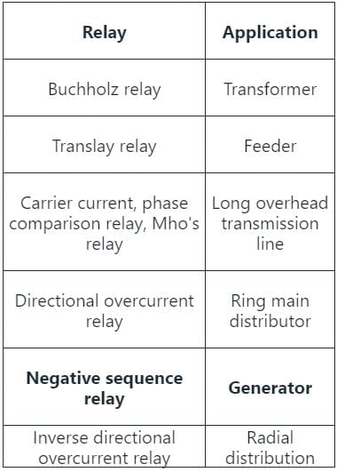
Negative sequence relay:
- It protects generators from the unbalanced load by detecting negative sequence current.
- A negative sequence current may cause a dangerous situation for the machine.
- Phase to phase fault mainly occurs because of the negative sequence component.
- The negative sequence relay has earthing which protects from phase-to-earth fault but not from phase-to-phase fault.
Note:
For an arcing fault where the arc resistance is significant an impedance or admittance relay will- a)over reach
- b)under reach
- c)the reach of relay is unaffected
- d)the reach will depend on the arcing resistance and may under reach or over reach.
Correct answer is option 'B'. Can you explain this answer?
For an arcing fault where the arc resistance is significant an impedance or admittance relay will
a)
over reach
b)
under reach
c)
the reach of relay is unaffected
d)
the reach will depend on the arcing resistance and may under reach or over reach.
|
|
Jatin Mukherjee answered |
The reach of a reactance relay is unaffected due to the arc resistance while an impedance and admittance relay under reaches.
The dielectric strength of SF6 is _______ that of air.- a)same as
- b)2 to 3 times
- c)10 times
- d)5 to 6 times
Correct answer is option 'B'. Can you explain this answer?
The dielectric strength of SF6 is _______ that of air.
a)
same as
b)
2 to 3 times
c)
10 times
d)
5 to 6 times
|
|
Vertex Academy answered |
- In SF6 circuit breaker, Sulphur hexafluoride gas is used as the arc quenching medium.
- Due to its low gaseous viscosity and high molecular weight, the SF6 gas can efficiently transfer heat by convection.
- It has high insulating properties and highly electronegative properties.
- Pure Sulphur hexafluoride gas is inert and thermally stable.
- SF6 has a very high dielectric strength (breakdown strength). It has 100 times more effective than air and oil as interrupting mediums.
- Its dielectric strength is 2.5 times that of air and 30% less than that of the dielectric oil.
Impedance relay is used for protection in:- a)medium transmission lines
- b)short transmission lines
- c)both long transmission lines and short transmission lines
- d)long transmission line
Correct answer is option 'A'. Can you explain this answer?
Impedance relay is used for protection in:
a)
medium transmission lines
b)
short transmission lines
c)
both long transmission lines and short transmission lines
d)
long transmission line
|
|
Saranya Mishra answered |
Impedance Relay in Protection
Protection in medium transmission lines is crucial to ensure the reliability and stability of the power system. Impedance relay is a commonly used protective device in these scenarios.
Function of Impedance Relay
- Impedance relay operates based on the impedance seen by the relay during a fault condition.
- It measures the ratio of voltage to current at the point of fault and compares it to a pre-set threshold to determine if a fault has occurred.
Application in Medium Transmission Lines
- Impedance relay is particularly effective in medium transmission lines where fault impedance levels are within a certain range.
- It can accurately detect faults and isolate the faulty section without causing unnecessary tripping of healthy sections.
Advantages in Medium Transmission Lines
- In medium transmission lines, impedance relay provides selective protection by accurately determining the fault location.
- It helps in minimizing downtime and reducing the impact of faults on the overall power system operation.
Conclusion
In conclusion, impedance relay is specifically designed for protection in medium transmission lines due to its ability to accurately detect faults and provide selective protection. Its application in this context plays a critical role in maintaining the reliability and stability of the power system.
The percent bias for a generator protection lies between- a)15 to 20%
- b)10 to 15%
- c)5 to 10%
- d)None of these
Correct answer is option 'A'. Can you explain this answer?
The percent bias for a generator protection lies between
a)
15 to 20%
b)
10 to 15%
c)
5 to 10%
d)
None of these
|
|
Niharika Basu answered |
Explanation:
Generator protection is an essential aspect of power system operation to ensure the safety and reliability of the power system. One of the critical parameters in generator protection is the percent bias.
The percent bias is a measure of the difference between the actual and expected values of the measured quantity. In generator protection, the measured quantity is the current or voltage, and the expected value is the threshold or setting value of the protection relay.
The percent bias is calculated as follows:
Percent bias = [(Measured value - Expected value) / Expected value] x 100
Ideally, the percent bias should be zero, indicating that the measured value is equal to the expected value. However, due to various factors such as instrument errors, temperature variations, and external interferences, some degree of bias is inevitable.
The acceptable range of percent bias for generator protection is typically between 15 to 20%. This range ensures that the protection relay operates reliably and does not trip unnecessarily due to small variations in the measured value.
If the percent bias is too low, the protection relay may not operate when it should, leading to a potential failure of the generator or other equipment. On the other hand, if the percent bias is too high, the protection relay may trip unnecessarily, leading to a disruption of power supply and unnecessary maintenance.
Therefore, it is essential to ensure that the percent bias of generator protection is within the acceptable range of 15 to 20%. Regular testing and calibration of the protection system can help to maintain the accuracy and reliability of the protection system.
Conclusion:
In conclusion, the acceptable range of percent bias for generator protection is between 15 to 20%. This range ensures that the protection relay operates reliably and does not trip unnecessarily due to small variations in the measured value. Regular testing and calibration of the protection system can help to maintain the accuracy and reliability of the protection system.
Which is the most serious problem in vacuum circuit breaker?- a)Poor arc quenching
- b)Low thermal stability
- c)Current chopping
- d)All of the above
Correct answer is option 'C'. Can you explain this answer?
Which is the most serious problem in vacuum circuit breaker?
a)
Poor arc quenching
b)
Low thermal stability
c)
Current chopping
d)
All of the above
|
|
Nilanjan Saini answered |
Current chopping is the most serious problem in vacuum circuit breakers (VCBs). Current chopping refers to the interruption of a high current flow in the circuit, resulting in the creation of an arc. This phenomenon can have several adverse effects on the performance and reliability of the VCB.
1. Definition of current chopping:
Current chopping occurs when the contacts of the circuit breaker start to separate, causing the current to be interrupted. Due to the high dielectric strength of the vacuum, the arc is initially unable to sustain itself. However, as the contacts move further apart, the arc starts to elongate and sustain itself. This can lead to several issues.
2. Adverse effects of current chopping:
- Overvoltages: The sudden interruption of current can result in overvoltages in the circuit. These overvoltages can damage the insulation of the equipment connected to the circuit, leading to insulation breakdown and equipment failure.
- Electromagnetic interference (EMI): The arc created during current chopping can generate electromagnetic radiation. This radiation can interfere with nearby electronic devices or communication systems, causing malfunctions or disruptions.
- Damage to circuit breaker contacts: The repeated occurrence of current chopping can cause excessive heating and erosion of the circuit breaker contacts. This leads to increased contact resistance and reduced performance of the circuit breaker.
- Reduced arc quenching capability: Current chopping can also impact the arc quenching capability of the VCB. The elongated arc can be difficult to extinguish, resulting in delayed or incomplete arc quenching. This can compromise the ability of the circuit breaker to safely interrupt the fault current.
- Increased wear and tear: The repeated occurrence of current chopping can accelerate the wear and tear of the circuit breaker components. This can reduce the lifespan of the VCB and increase the maintenance requirements.
3. Mitigation measures:
To mitigate the problem of current chopping, various techniques can be employed, such as:
- Pre-insertion resistors: These resistors are connected in series with the circuit breaker contacts to limit the rate of rise of recovery voltage (RRRV) during current interruption.
- Snubber circuits: Snubber circuits can be used to suppress the overvoltages generated during current interruption.
- Arc control devices: These devices, such as arc chutes or magnetic blowout coils, are designed to improve the arc quenching capability of the VCB and facilitate faster and more reliable current interruption.
Overall, current chopping is a critical problem in vacuum circuit breakers that can have several adverse effects on the performance and reliability of the circuit breaker and the connected equipment. Therefore, it is essential to understand and mitigate this issue to ensure the safe and efficient operation of the electrical system.
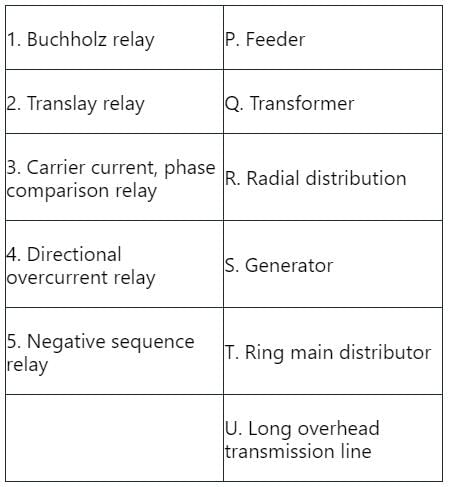
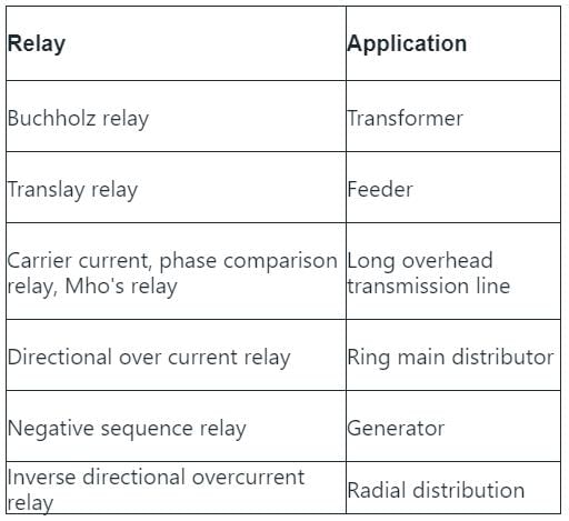
Which of the following relay is used for the protection of feeders and large busbars?- a)Under frequency relay
- b)Buchholz relay
- c)Distance relay
- d)Differential relay
Correct answer is option 'D'. Can you explain this answer?
Which of the following relay is used for the protection of feeders and large busbars?
a)
Under frequency relay
b)
Buchholz relay
c)
Distance relay
d)
Differential relay

|
Engineers Adda answered |
Differential relay:
- Differential relay operation depends on the phase difference of two or more electrical quantities.
- It works on the principle of comparison between the phase angle and the magnitude of the same electrical quantities.
- The differential relay is used for the protection of the feeder, large busbars, etc.
Distance relay:
- Distance relay is widely used for the protection of high-voltage AC transmission line and distribution lines.
- Distance protection schemes are commonly employed for providing the primary or main protection and backup protection for AC transmission line and distribution line against three-phase faults, phase-to-phase faults, and phase-to-ground faults.
Under frequency relay:
- Under frequency relay is used to protect the alternator when the frequency drops below the operating frequency.
- It is a backup protection for over fluxing (V/F) protection.
- Under frequency occurs due to turbine low speed, grid frequency fluctuation, etc.
- The generator can tolerate moderate under frequency operation provided voltage is within an acceptable limit.
Buchholz relay:
- Buchholz relay protects the transformer from internal faults.
- It is the gas actuated relay.
- The Buchholz relay is placed between the main tank and the conservator.
- Buchholz relay is used in the transformer having a rating higher than 500KVA.
- It is not used in a small transformer because of economic considerations.
If for an IDMT relay with a plug setting of 50% and a CT ration of 400/5, the current is 3000 A, then the plug setting multiplier would be:- a)7.5
- b)15.0
- c)18.75
- d)37.5
Correct answer is option 'B'. Can you explain this answer?
If for an IDMT relay with a plug setting of 50% and a CT ration of 400/5, the current is 3000 A, then the plug setting multiplier would be:
a)
7.5
b)
15.0
c)
18.75
d)
37.5

|
Bayshore Academy answered |
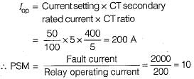
Concept:
Plug setting multiplier:
Plug setting multiplier is the ratio of fault current and the product of plug setting and CT ratio.
Plug setting multiplier 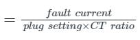
Calculation:
Plug setting = relay setting × secondary CT current
= 0.5 × 5 = 2.5
CT ratio = 400/5 = 80
Plug setting multiplier 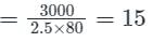
A vacuum circuit breaker can be used in which voltage range?- a)11-33 kV
- b)22-66 kV
- c)22-33 kV
- d)11-66 kV
Correct answer is option 'B'. Can you explain this answer?
A vacuum circuit breaker can be used in which voltage range?
a)
11-33 kV
b)
22-66 kV
c)
22-33 kV
d)
11-66 kV
|
|
Jatin Mukherjee answered |
Introduction:
A vacuum circuit breaker is a type of circuit breaker that uses a vacuum as the interrupting medium for breaking and making the electrical circuit. It is commonly used in medium voltage applications due to its compact size, high reliability, and low maintenance requirements.
Voltage Range:
The correct answer is option 'B', which states that a vacuum circuit breaker can be used in the voltage range of 22-66 kV. Let's understand why this is the correct answer.
Explanation:
A vacuum circuit breaker is designed to handle a specific voltage range based on its construction and insulation properties. Here are the reasons why option 'B' is the correct answer:
1. Insulation Level: The insulation level of a vacuum circuit breaker is determined by its ability to withstand the voltage stress during the interruption of the circuit. The insulation system used in a vacuum circuit breaker is designed to handle a specific voltage range.
2. Medium Voltage Applications: Vacuum circuit breakers are commonly used in medium voltage applications, which typically range from 3.3 kV to 33 kV. This voltage range includes options 'A' (11-33 kV) and 'C' (22-33 kV).
3. Higher Voltage Capability: Vacuum circuit breakers are capable of interrupting higher voltages than the options 'A' and 'C' mentioned above. They can handle voltages up to 66 kV, as stated in option 'B' (22-66 kV).
4. Advantages of Vacuum Circuit Breakers: Vacuum circuit breakers offer several advantages over other types of circuit breakers, such as:
- Compact Size: Vacuum circuit breakers are compact in size, making them suitable for installations where space is limited.
- High Reliability: Vacuum interrupters are highly reliable and have a long operational life.
- Low Maintenance: Vacuum circuit breakers require minimal maintenance due to the absence of arc quenching media like oil or gas.
- Fast Operation: Vacuum circuit breakers have fast operating times, ensuring quick interruption of the electrical circuit.
Conclusion:
In conclusion, a vacuum circuit breaker can be used in the voltage range of 22-66 kV. This range is suitable for medium voltage applications and offers several advantages such as compact size, high reliability, low maintenance, and fast operation.
A relay is connected to a 400/5 ratio current transformer with circuit setting of 150%. Calculate the plug setting multiplier when circuit carries a fault current of 3000 A.- a)5
- b)6
- c)8
- d)7
Correct answer is option 'A'. Can you explain this answer?
A relay is connected to a 400/5 ratio current transformer with circuit setting of 150%. Calculate the plug setting multiplier when circuit carries a fault current of 3000 A.
a)
5
b)
6
c)
8
d)
7
|
|
Engineers Adda answered |
Concept:
Plug setting multiplier is the ratio of fault current and the product of plug setting and CT ratio.
Plug setting multiplier 
Calculation:
Plug setting = relay setting × secondary CT current
= 1.5 × 5 = 7.5
CT ratio = 400/5 = 80
Plug setting multiplier 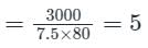
An over-current relay, having a current setting of 12.5% is connected to a supply circuit through a current transformer with a ratio of 400/5. The pick-up value of the current in Amperes is:- a)0.625
- b)10
- c)12.5
- d)15
Correct answer is option 'A'. Can you explain this answer?
An over-current relay, having a current setting of 12.5% is connected to a supply circuit through a current transformer with a ratio of 400/5. The pick-up value of the current in Amperes is:
a)
0.625
b)
10
c)
12.5
d)
15
|
|
Vibhor Goyal answered |
Concept:
The pick-up current of a relay is given by:
Pick-up current = Rated secondary current of CT × Current setting
Calculation:
Given, the CT ratio = 400/5
Secondary current = 5 A
Relay setting = 12.5%
Pick-up current = 5 × 0.125
Pick-up current = 0.625 A
A three-phase 33 kV, oil-circuit breaker is rated 1500 A, 2000 MVA, 2 s. The symmetrical breaking current for this breaker would be- a)40 kA
- b)25 kA
- c)35 kA
- d)50 kA
Correct answer is option 'C'. Can you explain this answer?
A three-phase 33 kV, oil-circuit breaker is rated 1500 A, 2000 MVA, 2 s. The symmetrical breaking current for this breaker would be
a)
40 kA
b)
25 kA
c)
35 kA
d)
50 kA
|
|
Machine Experts answered |
Concept:
Breaking current: It expresses the highest number of short-circuit currents that the breakers are capable of breaking under specified conditions of transient recovery voltage and power frequency voltage. It is expressed in kA (RMS) at contact separation. The breaking capacities are divided into two types.
- Symmetrical breaking capacity of a circuit breaker
- Asymmetrical breaking capacity of a circuit breaker
Rated symmetrical breaking current 
Making current of a circuit breaker is the peak value of the maximum current loop during sub transient condition including the DC component when the breaker closes.
Symmetrical making current = 2.55 × symmetrical breaking current
Calculation:
Rated current = 1500 A
MVA rating = 2000 MVA
Rated symmetrical breaking current 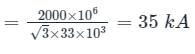
Insulation resistance of high voltage circuit breakers is more than - a)1 M ohm
- b)20 M ohm
- c)100 M ohm
- d)500 M ohm
Correct answer is option 'C'. Can you explain this answer?
Insulation resistance of high voltage circuit breakers is more than
a)
1 M ohm
b)
20 M ohm
c)
100 M ohm
d)
500 M ohm
|
|
Mahesh Singh answered |
Insulation Resistance of High Voltage Circuit Breakers
Insulation resistance is an important parameter in high voltage circuit breakers to ensure the safe and reliable operation of the equipment. It is a measure of the resistance offered by the insulation material to the flow of current through it. A high insulation resistance value indicates good insulation integrity.
Importance of Insulation Resistance
- Insulation resistance helps in identifying any insulation degradation or leakage current that can lead to equipment failure or electrical hazards.
- It helps in determining the health of the insulation system and predicts potential faults before they occur.
- Regular insulation resistance testing is necessary to maintain the operational reliability of high voltage circuit breakers.
Recommended Insulation Resistance Value
- The recommended insulation resistance value for high voltage circuit breakers is typically above 100 M ohm.
- A value of 100 M ohm or higher indicates that the insulation system is in good condition and can withstand the high voltage stresses during operation.
Testing and Maintenance
- Insulation resistance testing is usually performed using a megohmmeter or insulation resistance tester.
- Regular maintenance and testing of insulation resistance help in preventing breakdowns and ensuring the safety of the equipment and personnel.
- Any deviation from the recommended insulation resistance value should be investigated, and necessary actions should be taken to rectify the issue.
In conclusion, maintaining a high insulation resistance value in high voltage circuit breakers is crucial for ensuring the reliability and safety of the equipment. Regular testing and maintenance practices play a key role in achieving this goal.
What type of protection is used for LT lines passing through agricultural fields?- a)Zero factor protection
- b)Lewis defense
- c)Direct protection
- d)PVC protection
Correct answer is option 'D'. Can you explain this answer?
What type of protection is used for LT lines passing through agricultural fields?
a)
Zero factor protection
b)
Lewis defense
c)
Direct protection
d)
PVC protection
|
|
Bayshore Academy answered |
Zero factor protection: This option doesn't correspond to known electrical protection systems. The term "zero factor" does not define a type of standard protection that is used for electrical lines.
Lewis defense: This term is not associated with electrical protection systems. It might be confused with a strategy in game theory or related to military use but is not applicable in this context.
Direct protection: It generally refers to methods that protect equipment or lines directly, like using fuses, circuit breakers, or relays. However, these don't necessarily refer to specific methods to protect LT lines passing through fields.
PVC protection: It's a common practice to use PVC (Polyvinyl Chloride) for covering the LT (Low Tension) lines in agricultural fields. The PVC casing or conduits provide insulation, preventing direct exposure to the conducting wire, reducing the risk of electrical shock, and protecting the wires from damage due to weather conditions or farm-related activities. So this is the correct answer amongst the provided options.
If a transformer is provided with differentially connected relay. To prevent the mal operation of the relay, the relay restraining coil is biased with __________.- a)3rd harmonic
- b)2nd harmonic
- c)7th harmonic
- d)5th harmonic
Correct answer is option 'B'. Can you explain this answer?
If a transformer is provided with differentially connected relay. To prevent the mal operation of the relay, the relay restraining coil is biased with __________.
a)
3rd harmonic
b)
2nd harmonic
c)
7th harmonic
d)
5th harmonic
|
|
Sanchita Choudhary answered |
Transformer with Differentially Connected Relay and Biasing
Differentially connected relay is used to detect the fault in transformer windings. However, there is a possibility of mal-operation of the relay due to the presence of harmonics in the system. Therefore, to prevent the mal-operation of the relay, the relay restraining coil is biased with a specific harmonic.
Harmonic Biasing
Harmonic biasing is the process of adding a specific harmonic component to the restraining coil of the differential relay to reduce the mal-operation of the relay due to the presence of harmonics.
Second Harmonic Biasing
The second harmonic is the most commonly used harmonic for biasing the restraining coils of differential relays. The reason for using the second harmonic is that it has a phase angle of 180 degrees with respect to the fundamental frequency. Hence, it produces a magnetic flux that opposes the flux produced by the fundamental frequency, resulting in a cancellation of harmonics.
Advantages of Second Harmonic Biasing
• It reduces the mal-operation of the differential relay due to the presence of harmonics.
• It does not affect the sensitivity of the differential relay.
• It is easy to implement and does not require additional equipment.
Conclusion
To prevent the mal-operation of the differential relay, the relay restraining coil is biased with a specific harmonic. The second harmonic is the most commonly used harmonic for biasing the restraining coil as it cancels out the harmonics and does not affect the sensitivity of the relay.
Arcing contacts of a circuit breaker is made by using __________.- a)copper tungsten alloy
- b)aluminium alloy
- c)porcelain
- d)electrolytic copper
Correct answer is option 'A'. Can you explain this answer?
Arcing contacts of a circuit breaker is made by using __________.
a)
copper tungsten alloy
b)
aluminium alloy
c)
porcelain
d)
electrolytic copper
|
|
Machine Experts answered |
In a circuit breaker, the main contacts are usually made up of copper and conduct current in closed positions. Circuit breakers have low contact resistance and they are silver plated. The arcing contacts are solid, resistant to heat and are made up of copper tungsten alloy.
Important Points
Contact resistance is the resistance to current flow, due to surface conditions and other causes, when contacts are touching one another (in the closed condition of the device). This can occur between contacts of breakers.
The contact resistance is in the order of μΩ and it is approximately 20 μΩ.
While a transformer is energised, the differentially connected relay will- a)mal operate
- b)not mal operate
- c)mal operate for lagging loads
- d)never mal operate
Correct answer is option 'A'. Can you explain this answer?
While a transformer is energised, the differentially connected relay will
a)
mal operate
b)
not mal operate
c)
mal operate for lagging loads
d)
never mal operate
|
|
Pooja Patel answered |
There will be flow of inrush current at the energization of transformer which will let relay may operate.
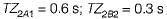
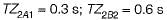
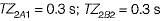
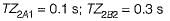
Relays A and B have to be coordinated on two adjacent line sections as shown in figure below. Zone-1 and Zone-2 settings are indicated on the diagram.
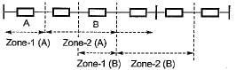
Which of the following indicates correct time setting for zone-2 of relays A and B?- a)
- b)
- c)
- d)
Correct answer is option 'B'. Can you explain this answer?
Relays A and B have to be coordinated on two adjacent line sections as shown in figure below. Zone-1 and Zone-2 settings are indicated on the diagram.
Which of the following indicates correct time setting for zone-2 of relays A and B?
Which of the following indicates correct time setting for zone-2 of relays A and B?
a)
b)
c)
d)

|
094_aditya Nayak answered |
How to solve this type of question?
The most suitable circuit breaker for voltages above 220 kV is- a)Vaccum CB
- b)SF6 CB
- c)Air blast CB
- d)Oil CB
Correct answer is option 'B'. Can you explain this answer?
The most suitable circuit breaker for voltages above 220 kV is
a)
Vaccum CB
b)
SF6 CB
c)
Air blast CB
d)
Oil CB
|
|
Aniket Shah answered |
Understanding Circuit Breakers for High Voltages
When selecting a circuit breaker for voltages above 220 kV, it's essential to consider various factors, including insulation, interrupting capacity, and environmental conditions. Among the options provided, SF6 circuit breakers (option 'B') are the most suitable.
Why Choose SF6 Circuit Breakers?
- Insulating Properties: SF6 (sulfur hexafluoride) has excellent dielectric properties, allowing it to effectively insulate high voltage systems.
- High Interrupting Capability: These circuit breakers can interrupt short circuit currents efficiently, which is crucial for protecting the system from fault conditions.
- Compact Design: SF6 circuit breakers have a smaller footprint compared to other types, making them ideal for urban and limited space applications.
- Low Maintenance: They require less maintenance due to the sealed environment that minimizes exposure to contaminants.
- Environmental Considerations: Although SF6 is a potent greenhouse gas, advancements in technology are being made for its recycling and management, reducing environmental impact.
Comparison with Other Types:
- Vacuum Circuit Breakers: Best for lower voltage applications (up to 38 kV); not effective for very high voltages.
- Air Blast Circuit Breakers: Suitable for medium voltages but less efficient at very high voltages due to air ionization issues.
- Oil Circuit Breakers: Older technology, larger, and generally less efficient for modern high voltage applications compared to SF6.
In summary, for voltages above 220 kV, SF6 circuit breakers are preferred due to their superior insulating properties, interrupting capabilities, and compact design, making them the right choice for high voltage applications.
In a 132 kV system, the series inductance up to the point of circuit breaker location is 50 mH. The shunt capacitance at the circuit breaker terminal is 0.05 μF. The critical value of resistance required to be connected across the circuit breaker contacts which will given no transient oscillation is:- a)50000 Ω
- b)50 Ω
- c)5000 Ω
- d)500 Ω
Correct answer is option 'D'. Can you explain this answer?
In a 132 kV system, the series inductance up to the point of circuit breaker location is 50 mH. The shunt capacitance at the circuit breaker terminal is 0.05 μF. The critical value of resistance required to be connected across the circuit breaker contacts which will given no transient oscillation is:
a)
50000 Ω
b)
50 Ω
c)
5000 Ω
d)
500 Ω
|
|
Vertex Academy answered |
Concept:
Circuit diagram for the resistance switching of circuit breaker is shown below.
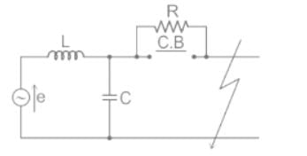
- Resistance Switching in Circuit Breaker refers to a method adopted for dampening the over voltage transients due to current chopping, capacitive current breaking etc.
- In this method, a shunt resistance is connected across the contacts of circuit breaker.
- The main role of shunt resistance R is to limit the growth of re-strike voltage and cause it to grow exponentially up to recovery voltage.
- R is so selected that the circuit becomes critically damped then re-strike voltage rises exponentially till recovery voltage is reached.
- The value of R for critical damping is
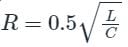
- Resistance Switching also reduces the oscillatory growth of Re-striking Voltage
- Voltage appearing across the electrodes of circuit breaker or switching voltage or prospective voltage

Calculation:
Given that V = 132 kV, C = 0.05 μF, L = 50 mH
Critical resistance, 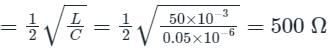
The frequency of the carrier in the case of carrier-current-pilot scheme is in the range of _________- a)50 kHz-500 kHz
- b)1 kHz-10 kHz
- c)25 kHz-50 kHz
- d)15 kHz-25kHz
Correct answer is option 'A'. Can you explain this answer?
The frequency of the carrier in the case of carrier-current-pilot scheme is in the range of _________
a)
50 kHz-500 kHz
b)
1 kHz-10 kHz
c)
25 kHz-50 kHz
d)
15 kHz-25kHz
|
|
Pooja Patel answered |
The carrier frequency has to be high in the case of carrier-current-pilot scheme.

Which relay is also called angle impedance relay?- a)Impedance relay
- b)Reactance relay
- c)Mho relay
- d)Frequency relay
Correct answer is option 'C'. Can you explain this answer?
Which relay is also called angle impedance relay?
a)
Impedance relay
b)
Reactance relay
c)
Mho relay
d)
Frequency relay
|
|
Harsh Kulkarni answered |
The relay that is also called an angle impedance relay is the Mho relay. Let's understand why this relay is referred to as an angle impedance relay.
1. Introduction to the Mho Relay:
The Mho relay is a distance relay used in power systems to protect transmission lines. It operates based on the measurement of impedance, which is the ratio of voltage to current in a circuit. The Mho relay is designed to operate when the impedance seen by the relay falls within a specific range.
2. Understanding Impedance:
Impedance is a complex quantity that represents the resistance and reactance of a circuit. It is denoted by the symbol Z and has both magnitude and phase angle. The magnitude of impedance represents the resistance, while the phase angle represents the reactance.
3. Angle Impedance Relay:
The Mho relay is often referred to as an angle impedance relay because it operates based on the angle of the impedance seen by the relay. The relay measures the impedance between the relay location and the fault location and compares it with a predetermined characteristic known as the Mho characteristic.
4. Mho Characteristic:
The Mho characteristic is a circular characteristic in the impedance plane. It is a circle with its center at the relay location and a radius representing the reach of the relay. The Mho characteristic is defined in terms of angle and impedance.
5. Operation of Mho Relay:
When a fault occurs in the transmission line, the impedance seen by the relay changes. The Mho relay measures the impedance and checks if it falls within the Mho characteristic circle. If the impedance falls within the characteristic circle, the relay operates and initiates the tripping of the circuit breaker.
6. Angle Measurement:
To determine whether the impedance falls within the Mho characteristic circle, the Mho relay measures the angle of the impedance. The angle represents the phase difference between the voltage and current. By comparing this angle with the Mho characteristic angle, the relay determines if the impedance is within the permissible range.
7. Advantages of Mho Relay:
The Mho relay has several advantages, including high speed of operation, reliable performance, and accurate fault detection. It is widely used in transmission line protection due to its ability to operate based on the angle of impedance.
In conclusion, the Mho relay is also called an angle impedance relay because it operates based on the angle of the impedance seen by the relay. It measures the impedance between the relay location and the fault location and compares it with the Mho characteristic, which is defined in terms of angle and impedance. By measuring the angle of the impedance, the relay determines if it falls within the permissible range and initiates the tripping of the circuit breaker if a fault is detected.
The factor which influences the acr de ionisation dominantly ________- a)line voltage
- b)magnitude of transient fault current
- c)speed of reclosure
- d)all of the mentioned
Correct answer is option 'A'. Can you explain this answer?
The factor which influences the acr de ionisation dominantly ________
a)
line voltage
b)
magnitude of transient fault current
c)
speed of reclosure
d)
all of the mentioned
|
|
Pooja Patel answered |
The line voltage determines the arc de ionisation in a circuit breaker.
Which of the following voltage ranges is correct for using a vacuum circuit breaker?- a)High voltage
- b)Very high voltage
- c)Low voltage
- d)Medium voltage
Correct answer is option 'D'. Can you explain this answer?
Which of the following voltage ranges is correct for using a vacuum circuit breaker?
a)
High voltage
b)
Very high voltage
c)
Low voltage
d)
Medium voltage
|
|
Machine Experts answered |
Vacuum Circuit Breaker
- A vacuum circuit breaker is a kind of circuit breaker where the arc quenching takes place in a vacuum medium.
- A vacuum that is used as the arc quenching medium in a circuit breaker is known as a vacuum circuit breaker because a vacuum gives high insulating strength due to superior arc quenching properties.
- Alloys like Copper-bismuth, silver-tellurium and copper-lead are the ideal materials to make VCB contacts.
- It is mainly used for medium voltage ranging from 11 KV to 33 KV.
- When the fault occurs in the system, the contacts of the breaker are moved apart and hence the arc is developed between them.
- When the current-carrying contacts are pulled apart, the temperature of their connecting parts is very high due to which ionization occurs.
- Due to the ionization, the contact space is filled with the vapour of positive ions which is discharged from the contact material.
- The density of vapour depends on the current in the arcing. Due to the decreasing mode of the current wave their rate of release of vapour falls and after the current zero, the medium regains its dielectric strength provided vapour density around the contacts is reduced.
- Hence, the arc does not restrike again because the metal vapour is quickly removed from the contact zone.
Additional Information
Vacuum Circuit Breaker:
Vacuum Circuit Breaker:
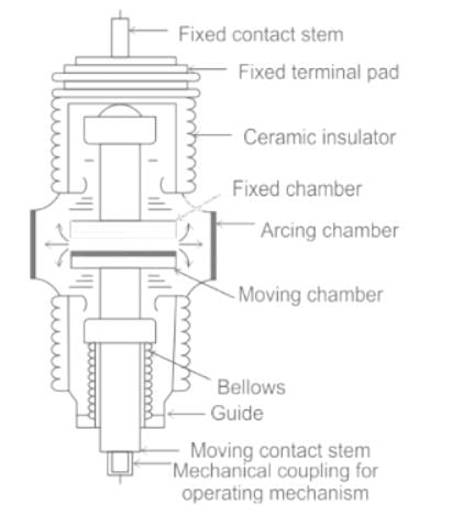
- A vacuum circuit breaker is a kind of circuit breaker where the arc quenching takes place in a vacuum medium.
- The operation of opening and closing of current carrying contacts and associated arc interruption take place in a vacuum chamber in the breaker which is called a vacuum interrupter.
- Vacuum circuit breakers are more commonly used at system voltage levels up to 72 kV.
- The vacuum contactor’s rated 1.2/3.6/7.2 kV is used for indoor metal enclosed control gear.
- The vacuum interrupters rated 3.6/7.2/12/36 kV is used for indoor metal-clad switch gear.
Kick fuses are used across relay coils to prevent relay operation during- a)heavy external faults
- b)inrush current of transformers when they are energized
- c)line to ground faults
- d)bolted faults
Correct answer is option 'B'. Can you explain this answer?
Kick fuses are used across relay coils to prevent relay operation during
a)
heavy external faults
b)
inrush current of transformers when they are energized
c)
line to ground faults
d)
bolted faults
|
|
Dhruv Datta answered |
Explanation:
Kick fuses are used across relay coils to prevent relay operation during inrush current of transformers when they are energized. This is because when a transformer is energized, it draws a high amount of current for a short duration of time. This current is known as inrush current.
The inrush current can be as high as 10 times the rated current of the transformer. This current can cause relay operation, which can lead to unnecessary tripping of the circuit breaker. To prevent this, kick fuses are used.
Kick fuses are small fuses that are connected in series with the relay coil. They are designed to blow when there is a sudden surge of current, such as inrush current. When the kick fuse blows, it prevents the relay from operating, thus preventing unnecessary tripping of the circuit breaker.
The kick fuse is designed to blow at a current slightly higher than the rated current of the relay coil. This ensures that the kick fuse only blows during inrush current and not during normal operation of the relay.
In summary, kick fuses are used across relay coils to prevent relay operation during inrush current of transformers when they are energized. They are designed to blow when there is a sudden surge of current, such as inrush current, to prevent unnecessary tripping of the circuit breaker.
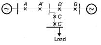
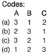
Chapter doubts & questions for Switchgear & Protection - Power Systems 2025 is part of Electrical Engineering (EE) exam preparation. The chapters have been prepared according to the Electrical Engineering (EE) exam syllabus. The Chapter doubts & questions, notes, tests & MCQs are made for Electrical Engineering (EE) 2025 Exam. Find important definitions, questions, notes, meanings, examples, exercises, MCQs and online tests here.
Chapter doubts & questions of Switchgear & Protection - Power Systems in English & Hindi are available as part of Electrical Engineering (EE) exam.
Download more important topics, notes, lectures and mock test series for Electrical Engineering (EE) Exam by signing up for free.
Power Systems
21 videos|69 docs|45 tests
|

Signup to see your scores go up within 7 days!
Study with 1000+ FREE Docs, Videos & Tests
10M+ students study on EduRev
|
© EduRev
|
Education Revolution
|


|


Signup to see your scores
go up
within 7 days!
within 7 days!
Takes less than 10 seconds to signup