


All India Mechanical Engineering Group
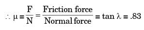
In orthogonal turning of low carbon steel pipe with principal cutting edge angle of 90°, the main cutting force is 1000 N and the feed force is 800 N. The shear angle is 25° and orthogonal rake angle is zero. Employing Merchants theory, the ratio of friction force to normal force acting on the cutting tool is[ME 2007]- a)1.56
- b)1.25
- c)0.80
- d)0.64
Correct answer is option 'C'. Can you explain this answer?
In orthogonal turning of low carbon steel pipe with principal cutting edge angle of 90°, the main cutting force is 1000 N and the feed force is 800 N. The shear angle is 25° and orthogonal rake angle is zero. Employing Merchants theory, the ratio of friction force to normal force acting on the cutting tool is
[ME 2007]
a)
1.56
b)
1.25
c)
0.80
d)
0.64

|
Gate Funda answered • 7 hours ago |
Here, ϕ = shear angle = 25º
λ = Friction angle,
α = rake angle = 0º
From Merchant''s theory, 2ϕ + λ - α = 90º
∴ λ = 90º - 50º = 40º
λ = Friction angle,
α = rake angle = 0º
From Merchant''s theory, 2ϕ + λ - α = 90º
∴ λ = 90º - 50º = 40º


A grinding wheel A 27 K 7 V is specified for finish grinding of a HSS cutting tool. What do you understand about the wheel from the above code.
Is this an appropriate choice?[ME 1994]- a)yes
- b)no, because abrasive is not correct
- c)no, grain size is not correct
- d)no, because grade is not correct choice
Correct answer is option 'C'. Can you explain this answer?
A grinding wheel A 27 K 7 V is specified for finish grinding of a HSS cutting tool. What do you understand about the wheel from the above code.
Is this an appropriate choice?
Is this an appropriate choice?
[ME 1994]
a)
yes
b)
no, because abrasive is not correct
c)
no, grain size is not correct
d)
no, because grade is not correct choice

|
Krishan Kumar answered • 7 hours ago |
Grain size is given for rough cut.
27 → rough cut
27 → rough cut

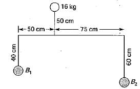
|
Hemanth Kumar
asked a question
|
Which of the following gives the names of the officers at the district level in the correct decending order?- a)Pradeshika, Rajuka, Yukta
- b)Rajuka, Yukta, Pradeshika
- c)Pradeshika, Yukta, Rajuka
- d)Yukta, Pradeshika, Rajuka
Correct answer is option 'A'. Can you explain this answer?
Which of the following gives the names of the officers at the district level in the correct decending order?
a)
Pradeshika, Rajuka, Yukta
b)
Rajuka, Yukta, Pradeshika
c)
Pradeshika, Yukta, Rajuka
d)
Yukta, Pradeshika, Rajuka
Choose the appropriate option to complete the following statement: 'After the meeting concluded, I ______ give my side of the story.’ - a)left to
- b)allowed to
- c)was allowed for
- d)was allowed to
Correct answer is option 'D'. Can you explain this answer?
Choose the appropriate option to complete the following statement:
'After the meeting concluded, I ______ give my side of the story.’
a)
left to
b)
allowed to
c)
was allowed for
d)
was allowed to
|
|
Nandita Chakraborty answered • 10 hours ago |
Understanding the Correct Option
The statement "After the meeting concluded, I ______ give my side of the story" requires a phrase that conveys permission or opportunity to do something after the meeting.
Analysis of the Options
- Option A: left to
- This phrase is not grammatically correct in this context. It implies a physical departure rather than add... more
A ball of radius 0.02 m falls under the influence of gravity through a viscous fluid. The terminal velocity of the ball is reached when the gravitational force is balanced by the drag force. If the drag coefficient is 0.5 and the fluid has a viscosity of 0.1 Pa-s, what is the terminal velocity of the ball?- a)0.5 m/s
- b)1.0 m/s
- c)1.5 m/s
- d)2.0 m/s
Correct answer is option 'B'. Can you explain this answer?
A ball of radius 0.02 m falls under the influence of gravity through a viscous fluid. The terminal velocity of the ball is reached when the gravitational force is balanced by the drag force. If the drag coefficient is 0.5 and the fluid has a viscosity of 0.1 Pa-s, what is the terminal velocity of the ball?
a)
0.5 m/s
b)
1.0 m/s
c)
1.5 m/s
d)
2.0 m/s
|
|
Kirti Bose answered • yesterday |
Understanding Terminal Velocity
When a ball falls through a viscous fluid, it eventually reaches a constant speed known as terminal velocity. At this point, the forces acting on the ball are balanced: the gravitational force is equal to the drag force exerted by the fluid.
Forces Acting on the Ball
- Gravitational Force (Fg): This force can be calculated using t... more
The axis about which moment of area is taken is known as ____________- a)Axis of area
- b)Axis of moment
- c)Axis of reference
- d)Axis of rotation
Correct answer is option 'C'. Can you explain this answer?
The axis about which moment of area is taken is known as ____________
a)
Axis of area
b)
Axis of moment
c)
Axis of reference
d)
Axis of rotation
|
|
Kirti Bose answered • yesterday |
Understanding the Moment of Area
The moment of area, also known as the area moment of inertia, is a crucial concept in mechanical engineering, particularly in structural analysis and design. It measures how the area of a shape is distributed relative to a specific axis.
Axis of Reference
The term "axis of reference" pertains to the axis about which this moment of area ... more
A mould has downsprue whose length is 20 cm and the cross sectional area at the base of the downsprue is 1 cm2. The downsprue feeds a horizontal runner leading into the mould cavity of volume 1000 cm3. The time required to fill the mould cavity will be[ME 2006]- a)4.05 s
- b)5.05 s
- c)6.05 s
- d)7.25 s
Correct answer is option 'B'. Can you explain this answer?
A mould has downsprue whose length is 20 cm and the cross sectional area at the base of the downsprue is 1 cm2. The downsprue feeds a horizontal runner leading into the mould cavity of volume 1000 cm3. The time required to fill the mould cavity will be
[ME 2006]
a)
4.05 s
b)
5.05 s
c)
6.05 s
d)
7.25 s
|
|
Kirti Bose answered • yesterday |
Understanding the Problem
To calculate the time required to fill the mould cavity, we need to determine the flow rate of the molten material through the downsprue and runner system.
Given Data:
- Length of downsprue = 20 cm
- Cross-sectional area of downsprue = 1 cm²
- Volume of mould cavity = 1000 cm³
Flow Rate Calculation
1. Velocity of ... more:
- The velocity (v) can be calculated using the formula:
v = √(2gh)
- Here, 'g' is the acceleration due to gravity (approximately 980 cm/s²), and 'h' is the height of molten metal in the downsprue, which we can assume to be equal to its length for simplicity, hence h = 20 cm.
2. Calculate Velocity:
- v = √(2 * 980 * 20) = √(39200) ≈ 198.0 cm/s
3. Flow Rate (Q):
- Q = A * v
- Where A is the cross-sectional area of the downsprue.
- Q = 1 cm² * 198.0 cm/s = 198.0 cm³/s
Time to Fill the Mould Cavity
4. Time (t):
- Time required to fill the mould cavity can be calculated using:
t = Volume / Flow Rate
- t = 1000 cm³ / 198.0 cm³/s ≈ 5.05 seconds
Conclusion
The calculated time required to fill the mould cavity is approximately 5.05 seconds, which corresponds to option B. This result is consistent with the principles of fluid dynamics in casting processes and highlights the importance of understanding flow rates in mould filling operations.
For an Oldham coupling used between two shafts, which among the following statements are correct?
I. Torsional load is transferred along shaft axis.
II. A velocity ratio of 1:2 between shafts is obtained without using gears.
III. Bending load is transferred transverse to shaft axis.
IV. Rotation is transferred along shaft axis.- a)I and III
- b)I and IV
- c)II and III
- d)II and IV
Correct answer is option 'B'. Can you explain this answer?
For an Oldham coupling used between two shafts, which among the following statements are correct?
I. Torsional load is transferred along shaft axis.
II. A velocity ratio of 1:2 between shafts is obtained without using gears.
III. Bending load is transferred transverse to shaft axis.
IV. Rotation is transferred along shaft axis.
I. Torsional load is transferred along shaft axis.
II. A velocity ratio of 1:2 between shafts is obtained without using gears.
III. Bending load is transferred transverse to shaft axis.
IV. Rotation is transferred along shaft axis.
a)
I and III
b)
I and IV
c)
II and III
d)
II and IV

|
Garima Nambiar answered • 2 days ago |
Understanding Oldham Couplings
Oldham couplings are mechanical devices used to connect two shafts that are not perfectly aligned. They are designed to transmit torque while accommodating misalignment and providing some degree of flexibility.
Correct Statements
The correct statements regarding Oldham couplings are:
I. Torsional load is transferred along shaft ax... more
- This statement is true. Oldham couplings are designed to transfer torque (torsional load) between the connected shafts along their axis.
II. A velocity ratio of 1:2 between shafts is obtained without using gears.
- This statement is false. Oldham couplings do not change the speed or provide a velocity ratio; they merely transmit motion and torque at the same speed between shafts.
III. Bending load is transferred transverse to shaft axis.
- This statement is false. Oldham couplings do not effectively transfer bending loads; they are primarily designed to handle torsional loads.
IV. Rotation is transferred along shaft axis.
- This statement is true. Oldham couplings facilitate the transfer of rotational motion along the axis of the shafts they connect.
Conclusion
Based on the evaluation of the statements:
- The correct answer is option 'B', which includes statements I and IV.
- These statements accurately reflect the operational principles of Oldham couplings, highlighting their role in torque transfer and alignment flexibility while confirming that they do not provide speed changes or handle bending loads effectively.

|
Vikramaditya
asked a question
|
Assertion A: Slavery was practised widely during the Chola empire.Reason R: Rajaraja invaded Cheras, Pandyas, and Ceylon to bring the trade with south-east Asian countries under his control and open the sea routes to China.- a)If Both A and R are true and R is the correct reason for A.
- b)If Both A and R are true but R is not the correct reason for A.
- c)If A is true but R is false.
- d)If R is true but A is false.
Correct answer is option 'D'. Can you explain this answer?
Assertion A: Slavery was practised widely during the Chola empire.
Reason R: Rajaraja invaded Cheras, Pandyas, and Ceylon to bring the trade with south-east Asian countries under his control and open the sea routes to China.
a)
If Both A and R are true and R is the correct reason for A.
b)
If Both A and R are true but R is not the correct reason for A.
c)
If A is true but R is false.
d)
If R is true but A is false.
Which of the following statements pertaining to slope of loaded beam is WRONG? The maximum slope- a)for a cantilever beam with a point load W at the free end is PL2/2 El.
- b)for a cantilever beam carrying a total load P which is uniformly distributed over the entire span is PL2/6 El.
- c)for a simply supported beam with an isolated load Pat mid span is PL2/ 16 EI.
- d)for a simply supported beam carrying a total load P which is uniformly distributed over the entire span is PL2/48 EI
Correct answer is option 'D'. Can you explain this answer?
Which of the following statements pertaining to slope of loaded beam is WRONG? The maximum slope
a)
for a cantilever beam with a point load W at the free end is PL2/2 El.
b)
for a cantilever beam carrying a total load P which is uniformly distributed over the entire span is PL2/6 El.
c)
for a simply supported beam with an isolated load Pat mid span is PL2/ 16 EI.
d)
for a simply supported beam carrying a total load P which is uniformly distributed over the entire span is PL2/48 EI

|
Priyanka Shah answered • 2 days ago |
Understanding Beam Slope Calculations
When analyzing the slope of loaded beams, it's crucial to apply the correct formulas for different loading conditions. Here’s a breakdown of the options provided:
Option A: Cantilever Beam with Point Load
- The maximum slope for a cantilever beam with a point load W at the free end is given by the formula PL2/2EI.
- This state... more
|
|
Elina Singh
asked a question
|
How does the Webb Space Telescope contribute to our understanding of star formation?- a) By observing gas and dust plumes from forming stars
- b) By detecting exoplanets
- c) By mapping the entire universe
- d) By observing black holes
Correct answer is option 'A'. Can you explain this answer?
How does the Webb Space Telescope contribute to our understanding of star formation?
a)
By observing gas and dust plumes from forming stars
b)
By detecting exoplanets
c)
By mapping the entire universe
d)
By observing black holes
|
|
Qamar Rao
asked a question
|
What key issue did the Supreme Court highlight regarding the National Judicial Appointments Commission (NJAC)?- a) It had broad political support
- b) It was necessary for transparency in judicial appointments
- c) It would enhance judicial independence
- d) It was unconstitutional due to the veto power of non-judicial members
Correct answer is option 'D'. Can you explain this answer?
What key issue did the Supreme Court highlight regarding the National Judicial Appointments Commission (NJAC)?
a)
It had broad political support
b)
It was necessary for transparency in judicial appointments
c)
It would enhance judicial independence
d)
It was unconstitutional due to the veto power of non-judicial members
|
|
Wasima Thakur
asked a question
|
What change did the Banking Laws (Amendment) Bill, 2024, introduce regarding nominees for bank deposits?- a) Banned the appointment of nominees altogether
- b) Required all nominees to be family members
- c) Allowed only one nominee per account
- d) Allowed up to four nominees for bank deposits
Correct answer is option 'D'. Can you explain this answer?
What change did the Banking Laws (Amendment) Bill, 2024, introduce regarding nominees for bank deposits?
a)
Banned the appointment of nominees altogether
b)
Required all nominees to be family members
c)
Allowed only one nominee per account
d)
Allowed up to four nominees for bank deposits
|
|
Arnav Trivedi
asked a question
|
Which of the following is NOT a primary area of focus for the Indian Ocean Rim Association (IORA)?- a) Renewable Energy Development
- b) Trade and Investment Facilitation
- c) Disaster Risk Management
- d) Maritime Safety and Security
Correct answer is option 'A'. Can you explain this answer?
Which of the following is NOT a primary area of focus for the Indian Ocean Rim Association (IORA)?
a)
Renewable Energy Development
b)
Trade and Investment Facilitation
c)
Disaster Risk Management
d)
Maritime Safety and Security
|
|
Qiana Iyer
asked a question
|
What aspect of deepfake technology has the Ministry of Electronics and Information Technology (MeitY) emphasized in its report to the Delhi High Court?- a) Complete ban on deepfake technology
- b) Mandatory disclosure and labeling standards for AI content
- c) Increased funding for deepfake technology development
- d) Encouragement of creative uses of deepfakes
Correct answer is option 'B'. Can you explain this answer?
What aspect of deepfake technology has the Ministry of Electronics and Information Technology (MeitY) emphasized in its report to the Delhi High Court?
a)
Complete ban on deepfake technology
b)
Mandatory disclosure and labeling standards for AI content
c)
Increased funding for deepfake technology development
d)
Encouragement of creative uses of deepfakes
|
|
Pranav Bhatia
asked a question
|
What was a significant concern raised about the two-exam scheme by critics?- a) It will standardize educational quality across India.
- b) It will reduce the number of exams students take.
- c) It will eliminate all forms of coaching.
- d) It may increase student stress and financial burdens.
Correct answer is option 'D'. Can you explain this answer?
What was a significant concern raised about the two-exam scheme by critics?
a)
It will standardize educational quality across India.
b)
It will reduce the number of exams students take.
c)
It will eliminate all forms of coaching.
d)
It may increase student stress and financial burdens.
|
|
Jayant Chopra
asked a question
|
What is the primary objective of the CBSE's two-exam scheme for Class 10 students?- a) To create a standardized testing system for all subjects
- b) To promote rote memorization among students
- c) To eliminate the need for coaching institutes
- d) To provide a second chance for students to improve their scores
Correct answer is option 'D'. Can you explain this answer?
What is the primary objective of the CBSE's two-exam scheme for Class 10 students?
a)
To create a standardized testing system for all subjects
b)
To promote rote memorization among students
c)
To eliminate the need for coaching institutes
d)
To provide a second chance for students to improve their scores


|
Sachin Kumar Savant
asked a question
|
Hot Spots within the earth help produce Geothermal Energy. What are these ‘Hot Spots’?
- a)Areas of intense pressure inside the mantle
- b)Region in the crust where hot molten rocks are trapped
- c)Regions of high volcanism on Earth’s surface
- d)Areas of intense magnetic activity within the upper mantle
Correct answer is option 'B'. Can you explain this answer?
Hot Spots within the earth help produce Geothermal Energy. What are these ‘Hot Spots’?
a)
Areas of intense pressure inside the mantle
b)
Region in the crust where hot molten rocks are trapped
c)
Regions of high volcanism on Earth’s surface
d)
Areas of intense magnetic activity within the upper mantle
|
|
Pankaj Patel
asked a question
|
Let A and B be two non-empty relations on a set S. Which of the following statements is false?- a)A and B are transitive ⇒ A∩B is transitive
- b)A and B are symmetric ⇒ A∪B is symmetric
- c)A and B are transitive ⇒ A∪B is not transitive
- d)A and B are reflexive ⇒ A∩B is reflexive
Correct answer is option 'C'. Can you explain this answer?
Let A and B be two non-empty relations on a set S. Which of the following statements is false?
a)
A and B are transitive ⇒ A∩B is transitive
b)
A and B are symmetric ⇒ A∪B is symmetric
c)
A and B are transitive ⇒ A∪B is not transitive
d)
A and B are reflexive ⇒ A∩B is reflexive

|
Manoj Mehta
asked a question
|
Two numbers such that the sum of twice the first number and thrice the second number is 100 and the sum of thrice the first number and twice the second number is 120. Which is larger number?- a)64
- b)72
- c)65
- d)32
- e)None of the Above
Correct answer is option 'D'. Can you explain this answer?
Two numbers such that the sum of twice the first number and thrice the second number is 100 and the sum of thrice the first number and twice the second number is 120. Which is larger number?
a)
64
b)
72
c)
65
d)
32
e)
None of the Above

|
Madhu Kumar
asked a question
|
A lubricant flows between two concentric cylinders, with an inner cylinder rotating at a speed of 4 m/s. The gap between the cylinders is 1 mm, and the dynamic viscosity of the lubricant is 0.05 Pa-s. What is the frictional resisting force per unit length of the cylinder?- a)0.5 N
- b)1.0 N
- c)1.5 N
- d)2.0 N
Correct answer is option 'B'. Can you explain this answer?
A lubricant flows between two concentric cylinders, with an inner cylinder rotating at a speed of 4 m/s. The gap between the cylinders is 1 mm, and the dynamic viscosity of the lubricant is 0.05 Pa-s. What is the frictional resisting force per unit length of the cylinder?
a)
0.5 N
b)
1.0 N
c)
1.5 N
d)
2.0 N

|
Plûtø Mürãli
asked a question
|
While water passes through a given pipe at mean velocity V the flow isfound to change from laminar to turbulent. If another fluid of specificgravity 0.8 and coefficient of viscosity 20% of that of water, is passed through the same pipe, the transition of flow from laminar to turbulentis expected if the flow velocity is: - a)2V
- b)V
- c)V/2
- d)V/4
Correct answer is option 'D'. Can you explain this answer?
While water passes through a given pipe at mean velocity V the flow isfound to change from laminar to turbulent. If another fluid of specificgravity 0.8 and coefficient of viscosity 20% of that of water, is passed through the same pipe, the transition of flow from laminar to turbulentis expected if the flow velocity is:
a)
2V
b)
V
c)
V/2
d)
V/4
|
|
Bhavna Singh
asked a question
|
Consider the following statements:
1. The Battle of Ten Kings was fought on the river Parushni, which is identical to the river Ravi.
2. The Bharatas were initially opposed by a host of ten chiefs, in which all of them were heads of non-Aryan tribes.
3. The Kurus combined with the Panchalas to establish their rule in the upper Gangetic basin during the later Vedic times.
Which of the statements given above is/are correct?
- a)1 Only
- b)1 and 2 Only
- c)1, and 3
- d)1, 2 and 3
Correct answer is option 'C'. Can you explain this answer?
Consider the following statements:
1. The Battle of Ten Kings was fought on the river Parushni, which is identical to the river Ravi.
2. The Bharatas were initially opposed by a host of ten chiefs, in which all of them were heads of non-Aryan tribes.
3. The Kurus combined with the Panchalas to establish their rule in the upper Gangetic basin during the later Vedic times.
Which of the statements given above is/are correct?
a)
1 Only
b)
1 and 2 Only
c)
1, and 3
d)
1, 2 and 3
|
|
Ashwini Nambiar
asked a question
|
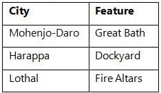
Consider the following statements about the end of the Harappan Civilization: - The decline of the Harappan Civilization can be attributed solely to the invasion by the Aryans.
- Environmental factors, such as changes in climate and river courses, played a significant role in the decline of the Harappan Civilization.
Which one of the following is correct in respect of the above statements?- a)Both Statement-I and Statement-II are correct and Statement-II is the correct explanation for Statement-I.
- b)Both Statement-I and Statement-II are correct but Statement-II is not the correct explanation for Statement-I.
- c)Statement-I is correct but Statement-II is incorrect.
- d)Statement-I is incorrect but Statement-II is correct.
Correct answer is option 'D'. Can you explain this answer?
Consider the following statements about the end of the Harappan Civilization:
- The decline of the Harappan Civilization can be attributed solely to the invasion by the Aryans.
- Environmental factors, such as changes in climate and river courses, played a significant role in the decline of the Harappan Civilization.
Which one of the following is correct in respect of the above statements?
a)
Both Statement-I and Statement-II are correct and Statement-II is the correct explanation for Statement-I.
b)
Both Statement-I and Statement-II are correct but Statement-II is not the correct explanation for Statement-I.
c)
Statement-I is correct but Statement-II is incorrect.
d)
Statement-I is incorrect but Statement-II is correct.


|
|
Baishali Kumar
asked a question
|
Consider the following statements: - The shadow zone of S-waves is created because they cannot travel through the Earth's liquid outer core.
- The Earth's outer core was deduced to be solid due to the behavior of S-waves.
- P-waves can be refracted by the liquid outer core, creating a shadow zone.
How many of the statements given above are correct?- a)Only one
- b)Only two
- c)All three
- d)None
Correct answer is option 'B'. Can you explain this answer?
Consider the following statements:
- The shadow zone of S-waves is created because they cannot travel through the Earth's liquid outer core.
- The Earth's outer core was deduced to be solid due to the behavior of S-waves.
- P-waves can be refracted by the liquid outer core, creating a shadow zone.
How many of the statements given above are correct?
a)
Only one
b)
Only two
c)
All three
d)
None
|
|
Snehal Tiwari
asked a question
|
During gas welding of copper sheets a neutral flame was used consuming 8 litres of acetylene.But the weld was found to be defective. So it was rewelded using an oxidizing flame. The likely consumption of oxygen in litres will be[PI 1993]- a)6
- b)8
- c)10
- d)16
Correct answer is option 'C'. Can you explain this answer?
During gas welding of copper sheets a neutral flame was used consuming 8 litres of acetylene.But the weld was found to be defective. So it was rewelded using an oxidizing flame. The likely consumption of oxygen in litres will be
[PI 1993]
a)
6
b)
8
c)
10
d)
16


|
Rohini S.
asked a question
|
A sum of Rs. 725 is lent in the beginning of a year at a certain rate of interest. After 8 months, a sum of Rs. 362.50 more is lent but at the rate twice the former. At the end of the year, Rs. 33.50 is earned as interest from both the loans. What was the original rate of interest?- a)5%
- b)3.46%
- c)4.5%
- d)None of these
Correct answer is option 'B'. Can you explain this answer?
a)
5%
b)
3.46%
c)
4.5%
d)
None of these
|
|
Khushi Varma
asked a question
|
The maximum marks per paper in 3 subjects in Mathematics , Physics and Chemistry are set in the ratio 1 : 2 : 3 respectively. Giri obtained 40% in Mathematics, 60% in Physics and 35% in Chemistry papers. What is overall percentage marks did he get overall?- a)44%
- b)32%
- c)50%
- d)60%
Correct answer is option 'A'. Can you explain this answer?
The maximum marks per paper in 3 subjects in Mathematics , Physics and Chemistry are set in the ratio 1 : 2 : 3 respectively. Giri obtained 40% in Mathematics, 60% in Physics and 35% in Chemistry papers. What is overall percentage marks did he get overall?
a)
44%
b)
32%
c)
50%
d)
60%
|
|
Omkar Iyer
asked a question
|
The price of a car is Rs. 4,50,000. It was insured to 80% of its price. The car was damaged completely in an accident and the insurance company paid 90% of the insurance. What was the difference between the price of the car and the amount received?- a)Rs.1,76,375
- b)Rs.3,24,000
- c)Rs.1,82,150
- d)Rs.1,26,000
Correct answer is option 'D'. Can you explain this answer?
The price of a car is Rs. 4,50,000. It was insured to 80% of its price. The car was damaged completely in an accident and the insurance company paid 90% of the insurance. What was the difference between the price of the car and the amount received?
a)
Rs.1,76,375
b)
Rs.3,24,000
c)
Rs.1,82,150
d)
Rs.1,26,000
|
|
Prasad Saha
asked a question
|
The prices of two articles are in the ratio 3 : 4. If the price of the first article be increased by 10% and that of the second by Rs. 4, the original ratio remains the same. The original price of the second article is:- a)Rs.40
- b)Rs.35
- c)Rs.10
- d)Rs.30
Correct answer is option 'A'. Can you explain this answer?
The prices of two articles are in the ratio 3 : 4. If the price of the first article be increased by 10% and that of the second by Rs. 4, the original ratio remains the same. The original price of the second article is:
a)
Rs.40
b)
Rs.35
c)
Rs.10
d)
Rs.30

|
Aravind Savyåsàçhi
asked a question
|
For the bracket bolted as shown in the above figure, the bolts will develop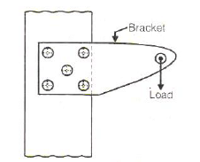
- a)primary tensile stresses and secondary shear stresses
- b)primary shear stresses and secondary shear stresses
- c)primary shear stresses and secondary tensile stresses
- d)primary tensile stresses and secondary compressive stresses
Correct answer is option 'B'. Can you explain this answer?
For the bracket bolted as shown in the above figure, the bolts will develop
a)
primary tensile stresses and secondary shear stresses
b)
primary shear stresses and secondary shear stresses
c)
primary shear stresses and secondary tensile stresses
d)
primary tensile stresses and secondary compressive stresses
|
|
Yashvi Choudhury
asked a question
|
What significant change has the Government of India implemented regarding the Gold Monetisation Scheme (GMS)?- a) Expansion of the Sovereign Gold Bond scheme
- b) Discontinuation of Medium-Term and Long-Term Deposits
- c) Introduction of new types of gold deposits
- d) Increase in the interest rates for gold deposits
Correct answer is option 'B'. Can you explain this answer?
What significant change has the Government of India implemented regarding the Gold Monetisation Scheme (GMS)?
a)
Expansion of the Sovereign Gold Bond scheme
b)
Discontinuation of Medium-Term and Long-Term Deposits
c)
Introduction of new types of gold deposits
d)
Increase in the interest rates for gold deposits
|
|
Muskaan Sen
asked a question
|
What is one of the main functions of the Commission on Genetic Resources for Food and Agriculture (CGRFA)?- a) To address plant genetic resources
- b) To establish new agricultural technologies
- c) To regulate agricultural practices globally
- d) To monitor food prices worldwide
Correct answer is option 'A'. Can you explain this answer?
What is one of the main functions of the Commission on Genetic Resources for Food and Agriculture (CGRFA)?
a)
To address plant genetic resources
b)
To establish new agricultural technologies
c)
To regulate agricultural practices globally
d)
To monitor food prices worldwide
|
|
Sahil Mehra
asked a question
|
In the context of glacier melting, what is one of the primary drivers contributing to the accelerated loss of glacier mass?- a) Increased snowfall
- b) Decreased rainfall
- c) Rising temperatures
- d) Improved conservation efforts
Correct answer is option 'C'. Can you explain this answer?
In the context of glacier melting, what is one of the primary drivers contributing to the accelerated loss of glacier mass?
a)
Increased snowfall
b)
Decreased rainfall
c)
Rising temperatures
d)
Improved conservation efforts
|
|
Akanksha Mehta
asked a question
|
What major reform does the Boilers Bill, 2024, introduce in relation to boiler operations?- a) Decriminalizes specific offenses related to boiler operations
- b) Increases criminal penalties for boiler-related offenses
- c) Eliminates all regulatory oversight on boiler operations
- d) Mandates the use of outdated safety standards
Correct answer is option 'A'. Can you explain this answer?
What major reform does the Boilers Bill, 2024, introduce in relation to boiler operations?
a)
Decriminalizes specific offenses related to boiler operations
b)
Increases criminal penalties for boiler-related offenses
c)
Eliminates all regulatory oversight on boiler operations
d)
Mandates the use of outdated safety standards
|
|
Prasad Desai
asked a question
|
What is a critical issue highlighted by the rise in vaccine-related petitions in India?- a) The effectiveness of vaccines
- b) Transparency in vaccine approval processes
- c) The cost of vaccines
- d) The availability of vaccines
Correct answer is option 'B'. Can you explain this answer?
What is a critical issue highlighted by the rise in vaccine-related petitions in India?
a)
The effectiveness of vaccines
b)
Transparency in vaccine approval processes
c)
The cost of vaccines
d)
The availability of vaccines
|
|
Bhavya Ahuja
asked a question
|
Which of the following statements is true regarding the recent earthquake in New Zealand's South Island?- a) It caused extensive damage to the North Island
- b) It highlights the geological activity in the region
- c) It is the first significant earthquake in New Zealand this year
- d) It had a magnitude of 7.2
Correct answer is option 'B'. Can you explain this answer?
Which of the following statements is true regarding the recent earthquake in New Zealand's South Island?
a)
It caused extensive damage to the North Island
b)
It highlights the geological activity in the region
c)
It is the first significant earthquake in New Zealand this year
d)
It had a magnitude of 7.2
|
|
Nikhil Majumdar
asked a question
|
In the context of economic growth in southern states of India, what is a significant challenge despite a large workforce?- a) Overproduction of goods
- b) High unemployment rates
- c) Excessive foreign investment
- d) Rapid industrial growth
Correct answer is option 'B'. Can you explain this answer?
In the context of economic growth in southern states of India, what is a significant challenge despite a large workforce?
a)
Overproduction of goods
b)
High unemployment rates
c)
Excessive foreign investment
d)
Rapid industrial growth
|
|
Aditi Chakraborty
asked a question
|
What is the primary objective of the Gold Monetisation Scheme (GMS) introduced by the Government of India?- a) To create more gold reserves for the Reserve Bank of India
- b) To promote the import of gold
- c) To mobilize idle gold and bring it into the formal economy
- d) To increase the production of gold in India
Correct answer is option 'C'. Can you explain this answer?
What is the primary objective of the Gold Monetisation Scheme (GMS) introduced by the Government of India?
a)
To create more gold reserves for the Reserve Bank of India
b)
To promote the import of gold
c)
To mobilize idle gold and bring it into the formal economy
d)
To increase the production of gold in India
|
|
Madhu Kumar
asked a question
|
A water tank is connected to a pipe with a diameter of 0.05 m. The pipe discharges water horizontally with a velocity of 2 m/s. What is the force exerted by the water on the pipe due to the discharge, assuming the density of water is 1000 kg/m³?- a)5 N
- b)10 N
- c)15 N
- d)20 N
Correct answer is option 'B'. Can you explain this answer?
A water tank is connected to a pipe with a diameter of 0.05 m. The pipe discharges water horizontally with a velocity of 2 m/s. What is the force exerted by the water on the pipe due to the discharge, assuming the density of water is 1000 kg/m³?
a)
5 N
b)
10 N
c)
15 N
d)
20 N


|
Natalie Nkatha
asked a question
|
Read the Passage carefully and answer the questions given below
But I did not want to shoot the elephant. I watched him beating his bunch of grass against hi... more
- a)being totally unconcerned
- b)pretending to be very busy
- c)a very superior attitude
- d)calm, dignified and affectionate disposition
Correct answer is option 'D'. Can you explain this answer??
Read the Passage carefully and answer the questions given below
But I did not want to shoot the elephant. I watched him beating his bunch of grass against hi... more
a)
being totally unconcerned
b)
pretending to be very busy
c)
a very superior attitude
d)
calm, dignified and affectionate disposition


|
|
Partho Jain
asked a question
|
Each of the following questions has a sentence with two blanks. Given below each question are five pairs of words. Choose the pair that best completes the sentence.Exhaustion of natural resources, destruction of individual initiative by governments, control over men’s minds by central __________ of education and propaganda are some of the major evils which appear to be on the increase as a result of the impact of science upon minds suited by _________ to an earlier kind of world.- a)tenets; fixation
- b)aspects; inhibitions
- c)institutions; inhibitions
- d)organs; tradition
Correct answer is option 'A'. Can you explain this answer?
Each of the following questions has a sentence with two blanks. Given below each question are five pairs of words. Choose the pair that best completes the sentence.
Exhaustion of natural resources, destruction of individual initiative by governments, control over men’s minds by central __________ of education and propaganda are some of the major evils which appear to be on the increase as a result of the impact of science upon minds suited by _________ to an earlier kind of world.
a)
tenets; fixation
b)
aspects; inhibitions
c)
institutions; inhibitions
d)
organs; tradition


|
207 Meena
asked a question
|
What was the main reason the Supreme Court halted the Lokpal's proceedings against a High Court judge?- a) To protect judicial independence
- b) To investigate corruption more thoroughly
- c) To transfer the case to another court
- d) To allow more time for the Lokpal to gather evidence
Correct answer is option 'A'. Can you explain this answer?
What was the main reason the Supreme Court halted the Lokpal's proceedings against a High Court judge?
a)
To protect judicial independence
b)
To investigate corruption more thoroughly
c)
To transfer the case to another court
d)
To allow more time for the Lokpal to gather evidence

|
|
Pranavi Choudhury
asked a question
|
What phenomenon does the Urban Heat Island (UHI) effect describe?- a) Increased rainfall in urban areas
- b) Reduced air quality in rural areas
- c) Increased vegetation growth in cities
- d) Higher temperatures in urban regions compared to rural areas
Correct answer is option 'D'. Can you explain this answer?
What phenomenon does the Urban Heat Island (UHI) effect describe?
a)
Increased rainfall in urban areas
b)
Reduced air quality in rural areas
c)
Increased vegetation growth in cities
d)
Higher temperatures in urban regions compared to rural areas
|
|
Anuj Chakraborty
asked a question
|
What key feature distinguishes Vikramshila University from other ancient educational institutions?- a) Its establishment by the Gupta Empire
- b) Its location in the Himalayas
- c) Its focus on mathematics
- d) Its specialization in Tantric Buddhism and occult studies
Correct answer is option 'D'. Can you explain this answer?
What key feature distinguishes Vikramshila University from other ancient educational institutions?
a)
Its establishment by the Gupta Empire
b)
Its location in the Himalayas
c)
Its focus on mathematics
d)
Its specialization in Tantric Buddhism and occult studies
|
|
Aashna Chakraborty
asked a question
|
What significant global event is the Commission on Genetic Resources for Food and Agriculture (CGRFA) associated with?- a) Global Health Initiatives
- b) Biodiversity conservation and sustainable agriculture
- c) International Trade Agreements
- d) Climate Change Summit
Correct answer is option 'B'. Can you explain this answer?
What significant global event is the Commission on Genetic Resources for Food and Agriculture (CGRFA) associated with?
a)
Global Health Initiatives
b)
Biodiversity conservation and sustainable agriculture
c)
International Trade Agreements
d)
Climate Change Summit

|
Shilpa Basu
asked a question
|
Two pipes can separately fill a tank in 20 hours and 30 hours respectively. Both the pipes are opened to fill the tank but when the tank is 3/4th full, a leak develops in, through which one-fourth of water supplied by both the pipes goes out. What is the total time taken to fill the tank?- a)18 hours
- b)14 hours
- c)15 hours
- d)13 hours
Correct answer is option 'D'. Can you explain this answer?
Two pipes can separately fill a tank in 20 hours and 30 hours respectively. Both the pipes are opened to fill the tank but when the tank is 3/4th full, a leak develops in, through which one-fourth of water supplied by both the pipes goes out. What is the total time taken to fill the tank?
a)
18 hours
b)
14 hours
c)
15 hours
d)
13 hours
|
|
Sandeep Sengupta
asked a question
|
Directions: In this type of questions, some particular words are assigned certain substituted names. Then a question is asked that is to be answered in the substituted code language.If 'bat' is 'racket', 'racket' is 'football', 'football' is 'shuttle', 'shuttle' is 'ludo' and 'ludo' is 'carrom', what is cricket played with?- a)racket
- b)football
- c)bat
- d)shuttle
- e)carom
Correct answer is option 'A'. Can you explain this answer?
Directions: In this type of questions, some particular words are assigned certain substituted names. Then a question is asked that is to be answered in the substituted code language.
If 'bat' is 'racket', 'racket' is 'football', 'football' is 'shuttle', 'shuttle' is 'ludo' and 'ludo' is 'carrom', what is cricket played with?
a)
racket
b)
football
c)
bat
d)
shuttle
e)
carom


|
|
Amar Choudhary
asked a question
|
Consider the following statements about the agricultural practices of the Harappan Civilization: - The Harappans were among the first to cultivate rice and cotton.
- Barley and wheat were the main crops, but rice cultivation was unknown to the Harappans.
Which one of the following is correct in respect of the above statements?- a)Both Statement-I and Statement-II are correct and Statement-II is the correct explanation for Statement-I.
- b)Both Statement-I and Statement-II are correct but Statement-II is not the correct explanation for Statement-I.
- c)Statement-I is correct but Statement-II is incorrect.
- d)Statement-I is incorrect but Statement-II is correct.
Correct answer is option 'C'. Can you explain this answer?
Consider the following statements about the agricultural practices of the Harappan Civilization:
- The Harappans were among the first to cultivate rice and cotton.
- Barley and wheat were the main crops, but rice cultivation was unknown to the Harappans.
Which one of the following is correct in respect of the above statements?
a)
Both Statement-I and Statement-II are correct and Statement-II is the correct explanation for Statement-I.
b)
Both Statement-I and Statement-II are correct but Statement-II is not the correct explanation for Statement-I.
c)
Statement-I is correct but Statement-II is incorrect.
d)
Statement-I is incorrect but Statement-II is correct.


|
|
Prasad Desai
asked a question
|
What has the Supreme Court mandated regarding the reassessment of the OBC list in West Bengal?- a) The existing OBC list should remain unchanged for the next five years.
- b) The list should be based solely on economic criteria.
- c) The OBC list must include all religious communities without exception.
- d) A new survey must be conducted within three months.
Correct answer is option 'D'. Can you explain this answer?
What has the Supreme Court mandated regarding the reassessment of the OBC list in West Bengal?
a)
The existing OBC list should remain unchanged for the next five years.
b)
The list should be based solely on economic criteria.
c)
The OBC list must include all religious communities without exception.
d)
A new survey must be conducted within three months.
|
|
Sahana Choudhary
asked a question
|
What significant action did the Calcutta High Court take regarding the OBC list in May 2024?- a) It ruled the OBC list illegal due to improper criteria.
- b) It mandated an immediate update of the OBC list.
- c) It added more communities to the OBC list.
- d) It approved the OBC list without changes.
Correct answer is option 'A'. Can you explain this answer?
What significant action did the Calcutta High Court take regarding the OBC list in May 2024?
a)
It ruled the OBC list illegal due to improper criteria.
b)
It mandated an immediate update of the OBC list.
c)
It added more communities to the OBC list.
d)
It approved the OBC list without changes.
|
|
Sanaya Sengupta
asked a question
|
What is one of the key benefits provided to selected startups within the support program?- a) Free marketing services for one year
- b) Grants of up to 5 lakh INR
- c) Tax exemptions for five years
- d) Access to international markets
Correct answer is option 'B'. Can you explain this answer?
What is one of the key benefits provided to selected startups within the support program?
a)
Free marketing services for one year
b)
Grants of up to 5 lakh INR
c)
Tax exemptions for five years
d)
Access to international markets
Fetching relevant content for you
Ask a doubt
Recommended Content
|
|
|
|
|
|
© EduRev
|
Education Revolution
|


|


Signup to see your scores
go up
within 7 days!
within 7 days!
Takes less than 10 seconds to signup