


All Exams >
Civil Engineering (CE) >
6 Months Preparation for GATE Civil Engg >
All Questions
All questions of Fluid Dynamics for Civil Engineering (CE) Exam
The continuity equation is based on the principle of-
- a)Law of conservation of energy
- b)Law of conservation of mass
- c)Law of conservation of momentum
- d)None of the mentioned
Correct answer is option 'B'. Can you explain this answer?
The continuity equation is based on the principle of-
a)
Law of conservation of energy
b)
Law of conservation of mass
c)
Law of conservation of momentum
d)
None of the mentioned
|
|
Aditya Deshmukh answered |
Explanation: Continuity equation is based on the the principle of conservation of mass.

The suction pipe of a pump rises at a slope of 2 vertically in 3 along the pipe, which is 10 cm in diameter. The pipe is 6 m long; its lower end being just below the surface of water in the reservoir. For design reasons, it is undesirable that pressure at inlet to the pump fall more than 75 kN⁄m2 below atmospheric pressure. Neglecting friction, make calculations for the maximum discharge (in L/s) that the pump may deliver.Take atmospheric pressure = 100 kN⁄m2Correct answer is 'Range: 66 to 67'. Can you explain this answer?
The suction pipe of a pump rises at a slope of 2 vertically in 3 along the pipe, which is 10 cm in diameter. The pipe is 6 m long; its lower end being just below the surface of water in the reservoir. For design reasons, it is undesirable that pressure at inlet to the pump fall more than 75 kN⁄m2 below atmospheric pressure. Neglecting friction, make calculations for the maximum discharge (in L/s) that the pump may deliver.
Take atmospheric pressure = 100 kN⁄m2
|
|
Sanya Agarwal answered |
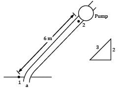
Let us consider a point a at the inlet of section pipe where the fluid is actually moving. Applying Bernoulli’s equation between a and 2
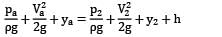
Where h represents any kind of losses in the flow. In this equation, ?? cannot be predicted as the fluid is moving, hence let us take point 1 on the free surface where the fluid particles start moving.
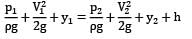
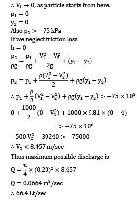
If we neglect friction loss
h = 0
V2 < 8.457="" />
Thus maximum possible discharge is
= 66.4 Lt/sec
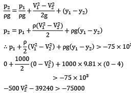
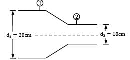
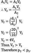
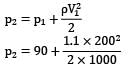
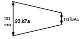
Consider steady, incompressible and irrotational flow through a reducer in a horizontal pipe, where the diameter is reduced from 20 cm to 10 cm. The absolute pressure in the 20 cm pipe just upstream of the reducer is 150 kPa absolute. The fluid has a vapour pressure of 50 kPa absolute and aspecific weight of 5 kN/m3. Neglecting frictional effects, the maximum discharge (in m3⁄sec) that can pass through the reducer without causing cavitation isCorrect answer is 'Range: 0.15 to 0.17'. Can you explain this answer?
Consider steady, incompressible and irrotational flow through a reducer in a horizontal pipe, where the diameter is reduced from 20 cm to 10 cm. The absolute pressure in the 20 cm pipe just upstream of the reducer is 150 kPa absolute. The fluid has a vapour pressure of 50 kPa absolute and a
specific weight of 5 kN/m3. Neglecting frictional effects, the maximum discharge (in m3⁄sec) that can pass through the reducer without causing cavitation is
|
|
Tanvi Shah answered |
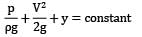
!s per Bernoulli’s equation
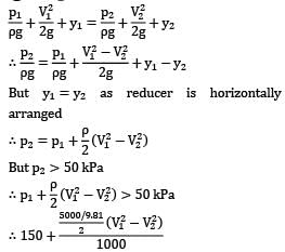
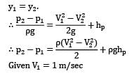
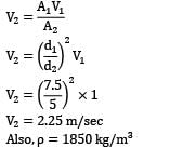
For flow along horizontal direction, an increase in flow velocity is accompanied by decrease in static pressure. Hence, applying continuity equation between section ① just upstream of the reducer and section ② downstream of reducer gives.
That is minimum pressure for flow along the reducer occurs at exit of reducer (section ②). This minimum pressure should be greater than vapor pressure else cavitation will occur in the system. ∴ p2 > 50 kPa !applying Bernoulli’s equation between section ① and ②
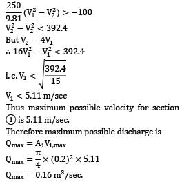
V1 < 5.11="" m="" />
Thus ,maximum possible velocity for section 1 is 5.11 m/sec.
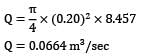
Therefore maximum possible discharge is
Qmax = A1V1,max
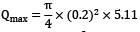
Qmax = 0.16 m3/sec.
A piezometer and a Pitot tube are tapped into a horizontal water pipe, as shown in figure. The velocity of water at the center of the pipe is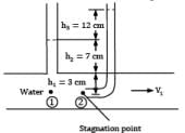
- a) 2.4 m/s
- b) 1.53 m/s
- c) 2.07 m/s
- d) 1.93 m/s
Correct answer is option 'B'. Can you explain this answer?
A piezometer and a Pitot tube are tapped into a horizontal water pipe, as shown in figure. The velocity of water at the center of the pipe is
a)
2.4 m/s
b)
1.53 m/s
c)
2.07 m/s
d)
1.93 m/s
|
|
Zoya Sharma answered |
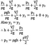
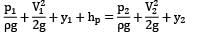
Applying Bernoulli’s equation between point ① and ②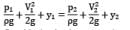
Considering basic assumptions of the equation to be applicable.
② is a stagnation point
i. e. V2 = 0 Also y1 = y2 Substituting the two conditions in Bernoulli’s equation
Which one of the follflowing is correct?- a)the frictional resistance depends on the nature of the surface area of contact
- b)the frictional resistance is independent of the nature of the surface area of contact
- c)the frictional resistance depends on the nature of the surface area of contact for laminar flows but is independent of the nature of the surface area of contact for turbulent flows
- d)the frictional resistance is independent of the nature of the surface area of contact for laminar flows but depends on the nature of the surface area of contact for turbulent flows
Correct answer is option 'D'. Can you explain this answer?
Which one of the follflowing is correct?
a)
the frictional resistance depends on the nature of the surface area of contact
b)
the frictional resistance is independent of the nature of the surface area of contact
c)
the frictional resistance depends on the nature of the surface area of contact for laminar flows but is independent of the nature of the surface area of contact for turbulent flows
d)
the frictional resistance is independent of the nature of the surface area of contact for laminar flows but depends on the nature of the surface area of contact for turbulent flows

|
Janhavi Datta answered |
Explanation: According to the laws of fluid friction, the frictional resistance is independent of the nature of the surface area of contact for laminar flows but depends on the nature of the surface area of contact for turbulent flows.
Venturimeter is based on integral form of Euler’s equation.- a)True
- b)False
Correct answer is option 'A'. Can you explain this answer?
Venturimeter is based on integral form of Euler’s equation.
a)
True
b)
False

|
Bijoy Kapoor answered |
True: Venturimeter is based on Bernoulli’s equation.
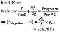
A light plane flies at 720 km/hr in standard air at an altitude of 1000 m. Determine the absolute stagnation pressure at the leading edge of the wing. Take, pair = 9.0 × 10⁴ N/m2, ρ = 1.1 kg/m3.- a) 90 kPa
- b) 119 kPa
- c) 112 kPa
- d) 100 kPa
Correct answer is option 'C'. Can you explain this answer?
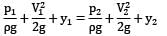
A light plane flies at 720 km/hr in standard air at an altitude of 1000 m. Determine the absolute stagnation pressure at the leading edge of the wing. Take, pair = 9.0 × 10⁴ N/m2, ρ = 1.1 kg/m3.
a)
90 kPa
b)
119 kPa
c)
112 kPa
d)
100 kPa
|
|
Tanvi Shah answered |
Consider the cross-section of wing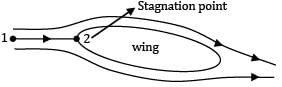
Similar to previous question
Also, p1 = 9 × 10⁴ Pa [for away point in atmosphere] V1 = 720 km/hr V1 = 200 m/sec y1 = y2
V2 = 0
Substituting these conditions in the Bernoulli’s equation
∴ p2 = 112 kPa
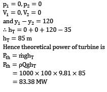
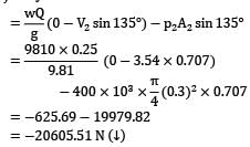
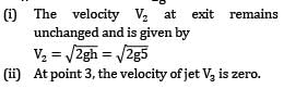
The rate of water through a vertical conical draft tube of a Kaplan turbine is 17.5 m3/s. The diameter of the draft tube on the side connected to the outlet of the turbine runner is 2.5 m and the average velocity at exit is 1.5 m⁄s. If the pressure at inlet to the tube is not to be less than the −0.7 bar, how far the tube should extend above the tail race. Neglect frictional effects and presume that exit of the draft tube lies 1.2 m below the tail water level.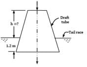 Correct answer is 'Range: 6.55 to 6.65'. Can you explain this answer?
The rate of water through a vertical conical draft tube of a Kaplan turbine is 17.5 m3/s. The diameter of the draft tube on the side connected to the outlet of the turbine runner is 2.5 m and the average velocity at exit is 1.5 m⁄s. If the pressure at inlet to the tube is not to be less than the −0.7 bar, how far the tube should extend above the tail race. Neglect frictional effects and presume that exit of the draft tube lies 1.2 m below the tail water level.
|
|
Zoya Sharma answered |
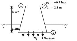
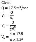
V1 = 3.565 m/sec
There is a possibility of mistake in the question, i.e. applying Bernoulli’s equation between section ① and ② and writing pressure at ② using hydrostatic law as ② lies 1.5 m below the free surface.
But please note that section ② represents flowing fluid, hence pressure cannot be predicted using hydrostatic law. Hence consider a point 3 far away from the tube along the centre streamline as shown.
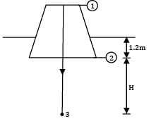
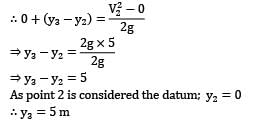
Apply Bernoulli’s equation between ① and ③
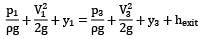
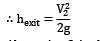
Where hexit is the head loss at exit of draft tube.
Note: At exit of pipe into a reservoir, entire kinetic head is lost.
Also point 3 is the far away point where the fluid particle comes to rest.
∴ V3 = 0
And P3 can be predicted by hydrostatic law as fluid is at rest P3 = ρg(H + 1.2) Substituting these conditions in Bernoulli’s equation
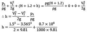
h = 6.6 m
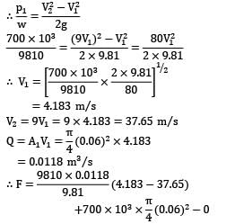
A pipe bend placed in a horizontal plane tapers from 50 cm diameter at inlet to 25 cm diameter at outlet. An oil of density 850 kg⁄m3 enters the reducing bend horizontally and gets turned through 45° clockwise direction. Measurements indicate that when oil flows at the rate of 0.45 m3⁄s, the pressure of 40 kN⁄m2 at the inlet section drops to 23 kN⁄m2 at the outlet section due to frictional effects. Make calculations for the magnitude of force on the bend. (in N)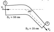 Correct answer is 'Range: 6350 to 6360'. Can you explain this answer?
A pipe bend placed in a horizontal plane tapers from 50 cm diameter at inlet to 25 cm diameter at outlet. An oil of density 850 kg⁄m3 enters the reducing bend horizontally and gets turned through 45° clockwise direction. Measurements indicate that when oil flows at the rate of 0.45 m3⁄s, the pressure of 40 kN⁄m2 at the inlet section drops to 23 kN⁄m2 at the outlet section due to frictional effects. Make calculations for the magnitude of force on the bend. (in N)
|
|
Sanvi Kapoor answered |
At section 1-1,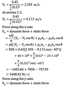
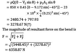
Force along the y-axis:
Fy = dynamic force + static force
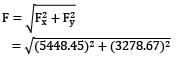
The magnitude of resultant force on the bend is
= 6358.87 N
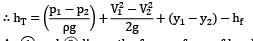
A submarine moves through seawater (SG = 1.03) at a depth of 50 m with velocity V0 = 5.0 m/s as shown in Fig. Determine the pressure at the stagnation point on the front of the submarine (in kPa).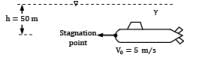 Correct answer is 'Range: 518 to 518.2'. Can you explain this answer?
A submarine moves through seawater (SG = 1.03) at a depth of 50 m with velocity V0 = 5.0 m/s as shown in Fig. Determine the pressure at the stagnation point on the front of the submarine (in kPa).

|
Gate Funda answered |
Consider relative motion of water with respect to submarines.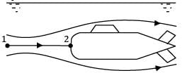
Maybe the streamline formation will be as shown in the figure. Consider the center most straight streamline 1 → 2 where 1 is a point far away from the submarine where the fluid particle is actually at absolute rest but in another frame of reference i.e. with respect to the submarine it is moving with a speed of 5 m/sec. ∴ V1 = 5.0 m/sec.
V2 = 0
and as fluid is at absolute rest at 1, p1 = ρgh where h = 50 m Let us apply Bernoulli’s equation between 1 and 2.
p2 = 518090 Pa or 518.09 kPa
Note: Even though flow is unsteady in actual but by changing the frame of reference and writing motion relative to submarine flow becomes steady and Bernoulli’s equation is applicable.
An air compressor draws air from the atmosphere through a bell-mouth entrance calibrated for measuring discharge passing through it in terms of height of water that rises in a single tube manometer installed in the duct which takes air from the bell mouth to the compressor. Determine the flowrate of air through the bell-mouth if the rise of water in the manometer tube is 25 cm and the duct has a diameter of 16 cm. For air density ρ = 1.2 kg⁄m3.Refer Fig. for the set-up.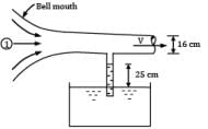 Correct answer is 'Range: 1.25 to 1.30'. Can you explain this answer?
An air compressor draws air from the atmosphere through a bell-mouth entrance calibrated for measuring discharge passing through it in terms of height of water that rises in a single tube manometer installed in the duct which takes air from the bell mouth to the compressor. Determine the flowrate of air through the bell-mouth if the rise of water in the manometer tube is 25 cm and the duct has a diameter of 16 cm. For air density ρ = 1.2 kg⁄m3.
Refer Fig. for the set-up.
|
|
Tanvi Shah answered |
Consider the horizontal streamline along the centerline of flow passage with two points shown. Point 1 is a far away point from where the fluid particle starts moving and point 2 is the gauge point in the passage where the manometer is installed.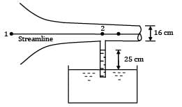
For air, specific weight, w = ρg = 1.2 × 9.81 = 11.77 N/m3.
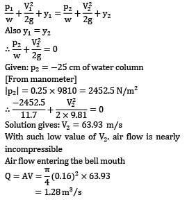
Applying Bernoulli's equation between point 1 and point 2 Point 1 is the far away point from where the fluid particle starts moving.
∴P1 = 0, V1 = 0
Solution gives: V2 = 63.93 m/s
With such low values of V2 air flow is nearly incompressible
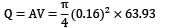
Air flow entering the bell mouth
=1.28 m3/s
The coefficient of discharge for an orifice meter is in the range- a)0.97 to 0.99
- b)0.93 to 0.98
- c)0.62 to 0.65
- d)0.51 to 0.55
Correct answer is option 'C'. Can you explain this answer?
The coefficient of discharge for an orifice meter is in the range
a)
0.97 to 0.99
b)
0.93 to 0.98
c)
0.62 to 0.65
d)
0.51 to 0.55

|
Vertex Academy answered |
Coefficient of discharge (Cd):
- It is the ratio of actual discharge to theoretical discharge.
- As in a pipe, frictional losses are present therefore Qactual will always be less than Qtheoretical.
Its value is always less than 1.
Cd = 0.62 - 0.65 for orifice meter
Cd = 0.95 - 0.98 for venturi meter
Cd = 0.62 - 0.65 for orifice meter
Cd = 0.95 - 0.98 for venturi meter
Air is drawn into a wind tunnel used for testing automobiles as shown in Fig. (ρair = 1.22 kg⁄m3 ; 1 mile = 1.6 km 1 inch = 2.54 cm)(i) Determine the manometer reading h, when the velocity in the test section is 60 mph. Note that there is a 1-in. column of oil on the water in the manometer.(ii) Determine the difference between the stagnation pressure on the front of the automobile and the pressure in the test section.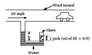
- a) h = 8.6 cm and 347 Pa
- b) h = 9.2 cm and 453 Pa
- c) h = 4.5 cm and 216 Pa
- d) h = 7.2 cm and 502 Pa
Correct answer is option 'C'. Can you explain this answer?
Air is drawn into a wind tunnel used for testing automobiles as shown in Fig. (ρair = 1.22 kg⁄m3 ; 1 mile = 1.6 km 1 inch = 2.54 cm)
(i) Determine the manometer reading h, when the velocity in the test section is 60 mph. Note that there is a 1-in. column of oil on the water in the manometer.
(ii) Determine the difference between the stagnation pressure on the front of the automobile and the pressure in the test section.
a)
h = 8.6 cm and 347 Pa
b)
h = 9.2 cm and 453 Pa
c)
h = 4.5 cm and 216 Pa
d)
h = 7.2 cm and 502 Pa
|
|
Vertex Academy answered |
The manometer will read the pressure of the air in the wind tunnel because of its taping position. So equating pressure at the same level of water (in manometer)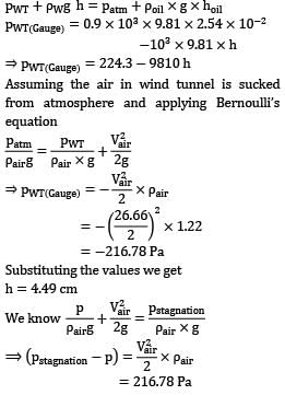
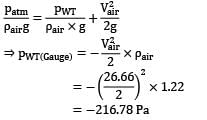
Assuming the air in wind tunnel is sucked from atmosphere and applying Bernoull’s equation
Substituting the value we get,
In a hydroelectric power plant, 100 m3 /s of water flows from an elevation of 120 m to a turbine, where electric power is generated (Fig). The total irreversible head loss in the piping system from point 1 to point 2 (excluding the turbine unit) is determined to be 35 m. Estimate the electric power output. (in MW)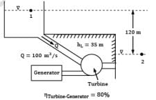 Correct answer is 'Range: 83 to 84'. Can you explain this answer?
In a hydroelectric power plant, 100 m3 /s of water flows from an elevation of 120 m to a turbine, where electric power is generated (Fig). The total irreversible head loss in the piping system from point 1 to point 2 (excluding the turbine unit) is determined to be 35 m. Estimate the electric power output. (in MW)
|
|
Tanvi Shah answered |
Considering steady state conditions, any fluid particle shall move along a streamline from 1 to 2, the streamline passing through the turbine. applying Bernoulli’s equation between 1 and 2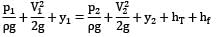
where hT is the head produced in the turbine and hf is the head loss.
As ① and ② lie on the free surfaces of head race and tail race respectively
What is the relationship between Orificemeter diameter and pipe diameter- a)Orificemeter diameter is 0.5 times the pipe diameter
- b)Orificemeter diameter is one third times the pipe diameter
- c)Orificemeter diameter is one fourth times the pipe diameter
- d)Orificemeter diameter is equal to the pipe diameter
Correct answer is option 'C'. Can you explain this answer?
What is the relationship between Orificemeter diameter and pipe diameter
a)
Orificemeter diameter is 0.5 times the pipe diameter
b)
Orificemeter diameter is one third times the pipe diameter
c)
Orificemeter diameter is one fourth times the pipe diameter
d)
Orificemeter diameter is equal to the pipe diameter
|
|
Rithika Reddy answered |
Explanation: None.
Which property of the fluid accounts for the major losses in pipes?- a)density
- b)specific gravity
- c)viscosity
- d)compressibility
Correct answer is option 'C'. Can you explain this answer?
Which property of the fluid accounts for the major losses in pipes?
a)
density
b)
specific gravity
c)
viscosity
d)
compressibility
|
|
Kavya Mehta answered |
Explanation: The major loss for the flow through the pipes is due to the frictional resistance between adjacent fluid layers sliding over each other. This resistance arises due to the presence of viscous property of the fluid.
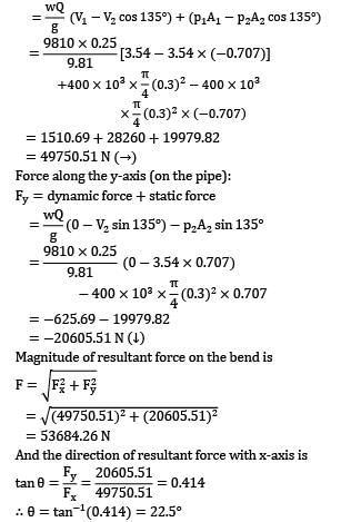
Water is flowing at a rate of 250 lt/sec. through a pipe of 30 cm diameter. If the pipe is bent by 135°, find the magnitude and direction of resultant force on the bend. The pressure of water flowing in the pipe is 400 kPa.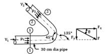
- a) F = 53.6 kN; θ = 22.5°
- b) F = 22.5 kN; θ = 53.6°
- c) F = 49.75 kN; θ = 22.5°
- d) F = 20.6 kN; θ = 35.6°
Correct answer is option 'A'. Can you explain this answer?
Water is flowing at a rate of 250 lt/sec. through a pipe of 30 cm diameter. If the pipe is bent by 135°, find the magnitude and direction of resultant force on the bend. The pressure of water flowing in the pipe is 400 kPa.
a)
F = 53.6 kN; θ = 22.5°
b)
F = 22.5 kN; θ = 53.6°
c)
F = 49.75 kN; θ = 22.5°
d)
F = 20.6 kN; θ = 35.6°
|
|
Vertex Academy answered |
The pipe is of uniform cross sectional area. Therefore, the flow velocities at section 1-1 and section 2-2 are the same.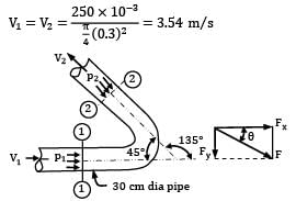
The pressure intensity is also the same at the two sections.
P1 = P2 = 400 kPa = 400 × 103 N⁄m2
Based on forces on pipe bends Force along the x-axis (on the pipe): Fx = dynamic force + static force
Force along the y -axis (on the pipe):
Fy = dynamic force + static force
Magnitude of resultant force on the bend is
And the direction of resultant force with x-axis is
An equal and opposite force will be required to hold the duct in position.
Note: That any particle in a free liquid jet experiences gravitational forces only and thus it can be solved as a projectile.
For a flow to be physically possible it must primarily satisfy which equation?- a)Equation of conservation of energy
- b)Equation of conservation of mass or continuity equation
- c)Equation of conservation of momentum
- d)None of the mentioned
Correct answer is option 'A'. Can you explain this answer?
For a flow to be physically possible it must primarily satisfy which equation?
a)
Equation of conservation of energy
b)
Equation of conservation of mass or continuity equation
c)
Equation of conservation of momentum
d)
None of the mentioned

|
Milan Saha answered |
Conservation Laws in Fluid Mechanics
Fluid mechanics is the study of how fluids (liquids and gases) behave under different conditions. It is governed by several fundamental principles, known as conservation laws, which describe the behavior of fluids in various physical processes. These conservation laws include the conservation of mass, momentum, and energy.
The Equation of Conservation of Mass
The conservation of mass, also known as the continuity equation, states that the mass of a fluid remains constant within a control volume, unless there are sources or sinks of mass. Mathematically, it can be expressed as:
ρ * A * v = constant
where ρ is the density of the fluid, A is the cross-sectional area of flow, and v is the velocity of the fluid. The continuity equation ensures that mass is conserved in any fluid flow, and it is applicable to both incompressible and compressible flows.
The Equation of Conservation of Momentum
The conservation of momentum states that the total momentum of a fluid remains constant within a control volume, unless there are external forces acting on it. Mathematically, it can be expressed as:
ρ * A * v * V + ∫∫∫ ρ * g * dV = constant
where V is the velocity vector of the fluid, ρ is the density of the fluid, A is the cross-sectional area of flow, g is the acceleration due to gravity, and the integral term represents the external forces acting on the fluid. The conservation of momentum ensures that the motion of fluid particles is governed by the forces acting on them.
The Equation of Conservation of Energy
The conservation of energy states that the total energy of a fluid remains constant within a control volume, unless there are energy transfers or conversions. Mathematically, it can be expressed as:
ρ * A * v * (E + 0.5 * V^2) + ∫∫∫ ρ * g * V * dV = constant
where E is the internal energy per unit mass of the fluid and the other terms have the same meanings as in the conservation of momentum equation. The conservation of energy ensures that the total energy of the fluid, including its internal and kinetic energy, is conserved in any physical process.
Conclusion
Among the three conservation equations, the conservation of energy (option A) is the primary equation that must be satisfied for a flow to be physically possible. This is because energy is a fundamental property of a fluid and any flow must obey the principle of energy conservation. The conservation of mass and momentum are also important in fluid mechanics, but they are derived from the conservation of energy equation and are secondary to it. Therefore, the correct answer is option A, the equation of conservation of energy.
Coefficient of discharge (Cd) in the orifice meter usually ranges between:- a)0.72 band 0.76
- b)0.83 and 0.87
- c)0.61 and 0.65
- d)0.95 an 0.99
Correct answer is option 'C'. Can you explain this answer?
Coefficient of discharge (Cd) in the orifice meter usually ranges between:
a)
0.72 band 0.76
b)
0.83 and 0.87
c)
0.61 and 0.65
d)
0.95 an 0.99

|
Pankaj Kapoor answered |
The coefficient of discharge (Cd) is a dimensionless factor that represents the efficiency of an orifice meter in measuring the flow rate of a fluid. It is defined as the ratio of the actual flow rate to the theoretical flow rate. The Cd value depends on various factors such as the shape and size of the orifice, the fluid properties, and the flow conditions.
The correct answer to the given question is option 'C', which states that the coefficient of discharge (Cd) in the orifice meter usually ranges between 0.61 and 0.65. This range is commonly accepted for orifice meters and is based on experimental data and industry standards. Let's discuss this in more detail:
1. Definition and Significance of Cd:
- The coefficient of discharge (Cd) is a dimensionless factor that relates the actual flow rate through an orifice to the theoretical flow rate.
- It takes into account the effect of various factors on the flow measurement accuracy, such as friction, turbulence, and contraction.
2. Factors Affecting Cd:
- Size and shape of the orifice: The Cd value depends on the shape and size of the orifice. Different shapes and sizes result in different flow patterns and affect the discharge coefficient.
- Fluid properties: The properties of the fluid, such as density and viscosity, affect the Cd value. Different fluids have different Cd values for the same orifice.
- Flow conditions: The flow conditions, such as Reynolds number and flow regime (turbulent or laminar), also influence the Cd value.
3. Experimental Data and Industry Standards:
- The range of Cd values mentioned in option 'C' (0.61-0.65) is commonly accepted in practice.
- These values are based on extensive experimental data and have been adopted in industry standards such as ISO 5167.
- The Cd values within this range provide a reasonable level of accuracy for flow measurements using orifice meters.
4. Variation in Cd Values:
- It is important to note that the Cd values can vary for different orifice designs, fluid properties, and flow conditions.
- The given range (0.61-0.65) is an average range and may not be applicable in all cases.
- Manufacturers and researchers may provide specific Cd values for their orifice designs based on calibration and testing.
In conclusion, the coefficient of discharge (Cd) in the orifice meter usually ranges between 0.61 and 0.65, as stated in option 'C'. This range is commonly accepted based on experimental data and industry standards. However, it is important to consider specific factors such as orifice design, fluid properties, and flow conditions, which may cause variations in Cd values.
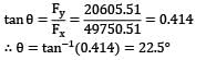
A 30 cm diameter pipe (called penstock) supplies water steadily to a turbine at 0.18 MN/m2. The water leaves the turbine on the exit side through a 60 cm pipe (called draft tube) with a pressure of −0.25 MN/m2. A vertical distance of 1.5 m separates the center of pipes at sections where measurements of pressure have been made. Calculate the power (in kW) delivered to the turbine from water if 0.25 m3 /s of water passes through the arrangement. Neglect frictional losses. Correct answer is 'Range: 112 to 113'. Can you explain this answer?
A 30 cm diameter pipe (called penstock) supplies water steadily to a turbine at 0.18 MN/m2. The water leaves the turbine on the exit side through a 60 cm pipe (called draft tube) with a pressure of −0.25 MN/m2. A vertical distance of 1.5 m separates the center of pipes at sections where measurements of pressure have been made. Calculate the power (in kW) delivered to the turbine from water if 0.25 m3 /s of water passes through the arrangement. Neglect frictional losses.
|
|
Zoya Sharma answered |
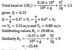
Head delivered to turbine = H1 − H2 = 20.48 + 25.4
= 45.92
Power delivered to turbine
= ρQg × Hdelivered
= 112.61 kW
Two pipes of diameters d1 and d2 converge to form a pipe of diameter 2d. If the liquid flows with a velocity of v1 and v2 in the two pipes, what will be the flow velocity in the third pipe?- a)v1 + v2
- b)v1 + v2/2
- c)v1 + v2/4
- d)2(v1 + v2)
Correct answer is option 'C'. Can you explain this answer?
Two pipes of diameters d1 and d2 converge to form a pipe of diameter 2d. If the liquid flows with a velocity of v1 and v2 in the two pipes, what will be the flow velocity in the third pipe?
a)
v1 + v2
b)
v1 + v2/2
c)
v1 + v2/4
d)
2(v1 + v2)
|
|
Lekshmi Das answered |
Solution:
Given, diameters of two pipes as d1 and d2 and the diameter of the third pipe as 2d.
Let the flow velocity in the third pipe be v.
According to the principle of continuity, the volume of liquid flowing per unit time through the three pipes must be the same.
Mathematically,
v1 * A1 = v2 * A2 = v * A3
where A1, A2, and A3 are the cross-sectional areas of pipes 1, 2, and 3 respectively.
The cross-sectional area of a pipe is proportional to the square of its diameter.
Mathematically,
A1 = π(d1/2)²
A2 = π(d2/2)²
A3 = π(2d/2)² = 4π(d²)
Substituting the values of A1, A2, and A3 in the continuity equation, we get
v1(d1/2)² = v2(d2/2)² = v(d²)
Simplifying the above equation, we get
v = (v1(d1/2)² + v2(d2/2)²)/d²
v = (v1d1² + v2d2²)/(4d²)
v = (v1/v2)(d1/d2)²(v2/4)
v = (v1v2/4)(d1/d2)²
v = v1v2/4(d2/d1)²
v = v1v2/4(1/(d1/d2)²)
v = v1v2/4(1/(d2/d1)²)
v = v1v2/4(1/(d2²/d1²))
v = v1v2/4(d1²/d2²)
v = v1v2/4(1/d2²)(d1²)
v = v1v2/4(d1²/d2²)
v = v1v2/4(4/1)
v = v1v2
Therefore, the flow velocity in the third pipe is v1v2/4. Hence, option C is the correct answer.
In a two dimensional flow, the component of the velocity along the X-axis and the Y-axis are u = ax2 + bxy and v = bxy + ay2. The condition for the flow field to be continuous is - a)independent of a and b
- b)independent of a and c
- c)independent of b and c
- d)independent of a, b and c
Correct answer is option 'D'. Can you explain this answer?
In a two dimensional flow, the component of the velocity along the X-axis and the Y-axis are u = ax2 + bxy and v = bxy + ay2. The condition for the flow field to be continuous is
a)
independent of a and b
b)
independent of a and c
c)
independent of b and c
d)
independent of a, b and c
|
|
Pallabi Tiwari answered |
Explanation: The condition for the flow field to be continuous is:
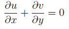
2ax + by + 2ay + bx = 0
x + y = 0
Hence, the condition for the flow field to be continuous is independent of a, b and c.
2ax + by + 2ay + bx = 0
x + y = 0
Hence, the condition for the flow field to be continuous is independent of a, b and c.
For a nozzle, the vertical intercept between EGL and HGL- a)increases
- b)decreases
- c)remains constant
- d)may increase or decrease
Correct answer is option 'A'. Can you explain this answer?
For a nozzle, the vertical intercept between EGL and HGL
a)
increases
b)
decreases
c)
remains constant
d)
may increase or decrease
|
|
Juhi Choudhary answered |
Explanation: The vertical intercept between EGL and HGL is equal to the kinetic head. For a nozzle, the cross-sectional area decreases in the direction of flow leading to an increase in the velocity of flow across the pipe. Since the kinetic head increases, the vertical intercept between EGL and HGL will increase.
A smooth pipe of diameter 200 mm carries water. The pressure in the pipe at section S1 (elevation:10 m) is 50 kPa. At section S2 (elevation:12 m) the pressure is 20 kPa and velocity is 2 ms-1. Density of water is 1000 kgm-3 and acceleration due to gravity is 9.8 ms-2. Which of the following is TRUE- a)Flow is from S1 to S2 and head loss is 0.53 m
- b)Flow is from S2 to S1 and head loss is 0.53 m
- c)Flow is from S1 to S2 and head loss is 1.06 m
- d)Flow is from S2 to S1 and head loss is 1.06 m
Correct answer is option 'C'. Can you explain this answer?
A smooth pipe of diameter 200 mm carries water. The pressure in the pipe at section S1 (elevation:10 m) is 50 kPa. At section S2 (elevation:12 m) the pressure is 20 kPa and velocity is 2 ms-1. Density of water is 1000 kgm-3 and acceleration due to gravity is 9.8 ms-2. Which of the following is TRUE
a)
Flow is from S1 to S2 and head loss is 0.53 m
b)
Flow is from S2 to S1 and head loss is 0.53 m
c)
Flow is from S1 to S2 and head loss is 1.06 m
d)
Flow is from S2 to S1 and head loss is 1.06 m
|
|
Hrishikesh Chakraborty answered |
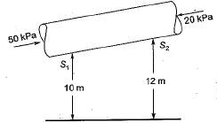
Applying Bernoulli’s equation between section S1 and S2
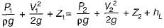
as area is constant velocity head will be same
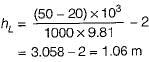
thus flow from S1 to S2 and head loss is 1.06 m.
On which of the factors does the co-efficent of bend in a pipe depend?- a)angle of bend and radius of curvature of the bend
- b)angle of bend and radius of the pipe
- c)radius of curvature of the bend and pipe
- d)radius of curvature of the bend and pipe and angle of bend
Correct answer is option 'D'. Can you explain this answer?
On which of the factors does the co-efficent of bend in a pipe depend?
a)
angle of bend and radius of curvature of the bend
b)
angle of bend and radius of the pipe
c)
radius of curvature of the bend and pipe
d)
radius of curvature of the bend and pipe and angle of bend

|
Isha Bajaj answered |
Factors affecting the coefficient of bend in a pipe are the angle of bend, radius of curvature of the bend, and the radius of the pipe.
1. Angle of bend:
The angle of bend refers to the amount of change in direction that the pipe makes at the bend. It is measured in degrees. The greater the angle of bend, the more significant the impact on the coefficient of bend. A sharper bend will result in a higher coefficient of bend.
2. Radius of curvature of the bend:
The radius of curvature of the bend is the radius of the imaginary circle formed by the bend. It is measured in meters. The smaller the radius of curvature, the more severe the bend, and therefore, the higher the coefficient of bend. A smaller radius of curvature indicates a tighter bend, which results in a higher resistance to flow and a higher coefficient of bend.
3. Radius of the pipe:
The radius of the pipe refers to the distance from the center of the pipe to its inner or outer surface. It is also measured in meters. The larger the radius of the pipe, the less impact it has on the coefficient of bend. A larger radius of the pipe indicates a more gradual bend, resulting in a lower resistance to flow and a lower coefficient of bend.
Interaction between factors:
The coefficient of bend depends on the interaction between these factors. For example, a larger angle of bend will increase the resistance to flow, leading to a higher coefficient of bend. Similarly, a smaller radius of curvature will also increase the resistance to flow, resulting in a higher coefficient of bend. The radius of the pipe, on the other hand, has an inverse relationship with the coefficient of bend. A larger radius of the pipe will decrease the resistance to flow and lower the coefficient of bend.
In conclusion, the coefficient of bend in a pipe depends on the angle of bend, radius of curvature of the bend, and the radius of the pipe. These factors interact with each other to determine the resistance to flow and ultimately affect the coefficient of bend.
Which of the following is true?- a)EGL always drops in the direction of c
- b)EGL always rises in the direction of flow
- c)EGL always remains constant in the direction of flow
- d)EGL may or may not in the direction of flow
Correct answer is option 'A'. Can you explain this answer?
Which of the following is true?
a)
EGL always drops in the direction of c
b)
EGL always rises in the direction of flow
c)
EGL always remains constant in the direction of flow
d)
EGL may or may not in the direction of flow

|
Anushka Yadav answered |
Explanation: EGL is obtained by plotting total head at various points along the axis of the pipe. Since the total head decreases in the direction of flow, EGL will always drop in that direction.
Orifice meters have ______ head loss as compared to venturimeters.- a)higher
- b)lesser
- c)half
- d)similar
Correct answer is option 'A'. Can you explain this answer?
Orifice meters have ______ head loss as compared to venturimeters.
a)
higher
b)
lesser
c)
half
d)
similar
|
|
Sanvi Kapoor answered |
Both venturimeter and orificemeter is used to calculate the rate of flow of liquid flowing through a pipe, they just differs in construction.
Comparison of Venturimeter and Orifacemeter:
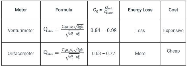
where, a0 = theoretical throat area, a1 = area at the inlet, h = difference in head, and Cd = coefficient of discharge.
As energy loss is more in orifice meter, they have higher head losses.
Comparison of Venturimeter and Orifacemeter:
where, a0 = theoretical throat area, a1 = area at the inlet, h = difference in head, and Cd = coefficient of discharge.
As energy loss is more in orifice meter, they have higher head losses.
In the equipment shown in Fig., a pump draws a solution (specific gravity 1.85) from a store tank through a 7.5 cm steel pipe in which the flow velocity is 1.0 m⁄s . The pump discharges through a 5 cm steel pipe to an overhead tank, the end of the discharge pipe is 15 m above the level of the solution in the feed tank, and the friction losses in the entire piping system are 5 m. What is the pressure difference in (in kPa) maintained across the pump? Take pump efficiency as 60 percent.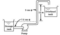 Correct answer is 'Range: 363 to 364'. Can you explain this answer?
In the equipment shown in Fig., a pump draws a solution (specific gravity 1.85) from a store tank through a 7.5 cm steel pipe in which the flow velocity is 1.0 m⁄s . The pump discharges through a 5 cm steel pipe to an overhead tank, the end of the discharge pipe is 15 m above the level of the solution in the feed tank, and the friction losses in the entire piping system are 5 m. What is the pressure difference in (in kPa) maintained across the pump? Take pump efficiency as 60 percent.

|
Engineers Adda answered |
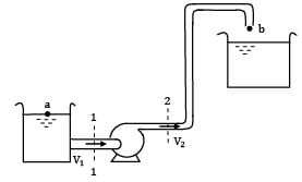
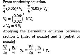
Let us consider 1 and 2 as the inlet and outlet of the pump. Applying Bernoulli’s equation between ① and ②
Considering negligible flow losses in the pump. hp represents the head supplied to the fluid by the pump.
As nothing is mentioned about relative elevation of the inlet an outlet, let us consider
By continuity equation
Thus to calculate p2 − p1 (i.e. the pressure difference across the pump, value of hp is required).
Therefore let us consider a, i.e. the top surface of oil in the reservoir and b which is just outside the exit of discharge point.
For steady state conditions any particle moves from a to b passing through the suction pipe, pump and the discharge pipe. ∴ Applying Bernoulli’s equation between a and b
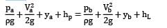
hL represents head losses in the piping system. lies on the free surface of the liquid, which is exposed to the atmosphere, and from the same point, fluid particles start moving. ∴ Pa = 0
Va = 0
Also b is a point in a free liquid jet coming out from the discharge pipe.
Also yb - ya = 15 m
Hence,
P2 - P1 = 36387 Pa
or 363.807kPa
In a two dimensional flow, the component of the velocity along the X-axis and the Y-axis are u = ax2 + bxy + cy2 and v = cxy. What should be the condition for the flow field to be continuous? - a)a + c = 0
- b)b + c = 0
- c)2a + c = 0
- d)2b + c = 0
Correct answer is option 'C'. Can you explain this answer?
In a two dimensional flow, the component of the velocity along the X-axis and the Y-axis are u = ax2 + bxy + cy2 and v = cxy. What should be the condition for the flow field to be continuous?
a)
a + c = 0
b)
b + c = 0
c)
2a + c = 0
d)
2b + c = 0
|
|
Pallabi Tiwari answered |
Explanation: According to the condition for continuity,

2ax + cx = 0
2a + c = 0.
2ax + cx = 0
2a + c = 0.
For a diffuser, the vertical intercept between EGL and HGL- a)increases
- b)decreases
- c)remains constant
- d)may increase or decrease
Correct answer is option 'B'. Can you explain this answer?
For a diffuser, the vertical intercept between EGL and HGL
a)
increases
b)
decreases
c)
remains constant
d)
may increase or decrease
|
|
Juhi Choudhary answered |
Explanation: The vertical intercept between EGL and HGL is equal to the kinetic head. For a diffuser, the cross-sectional area increases in the direction of flow leading to a decrease in the velocity of flow across the pipe. Since the kinetic head decreases, the vertical intercept between EGL and HGL will decrease.
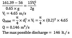
Gasoline flows through a constriction in a horizontal pipe where the diameter is reduced from 20 cm to 10 cm. The pressure in the 20 cm pipe just upstream of constriction is 60 kPa. Considering no loss of energy in the flow passage, make calculations for the maximum discharge (in L/s) that can be passed through the constriction without the occurrence of cavitation. The barometer reads 76 cm of mercury and for gasoline vapour pressure is 56 kPa (abs) and density is 650 kg/m3.Correct answer is 'Range: 145 to 147'. Can you explain this answer?
Gasoline flows through a constriction in a horizontal pipe where the diameter is reduced from 20 cm to 10 cm. The pressure in the 20 cm pipe just upstream of constriction is 60 kPa. Considering no loss of energy in the flow passage, make calculations for the maximum discharge (in L/s) that can be passed through the constriction without the occurrence of cavitation. The barometer reads 76 cm of mercury and for gasoline vapour pressure is 56 kPa (abs) and density is 650 kg/m3.
|
|
Lavanya Menon answered |
Since nothing is mentioned about the pressure at inlet. We assume it is measured by a pressure gauge, in terms of gauge. For cavitation to be avoided, the minimum pressure can’t go below 56 kPa (abs). Applying continuity at inlet and outlet
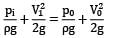
Pi = 60 × 103 + Patm
= 60 × 103 + 13.6 × 10³ × g × 0.76
= 161.39 kPa
P0 = 56 kPa
Substituting values
Orifice meter consists of a flat rectangular plate.- a)True
- b)False
Correct answer is option 'B'. Can you explain this answer?
Orifice meter consists of a flat rectangular plate.
a)
True
b)
False

|
Sharmila Gupta answered |
Introduction:
The orifice meter is a type of flow meter used to measure the flow rate of fluid through a pipe. It consists of a flat rectangular plate with a small hole, known as an orifice, through which the fluid passes. This question is asking whether the given statement about the orifice meter is true or false.
Explanation:
The correct answer is option 'B', which states that the given statement is false. Let's understand why this is the correct answer.
Orifice Plate:
The orifice meter typically consists of a circular orifice plate rather than a flat rectangular plate. The orifice plate is installed perpendicular to the flow direction and creates a pressure difference across itself. This pressure difference is then used to determine the flow rate of the fluid.
Working Principle:
When the fluid passes through the orifice plate, it experiences a reduction in cross-sectional area, leading to an increase in fluid velocity. According to Bernoulli's principle, this increase in velocity corresponds to a decrease in pressure. The pressure difference across the orifice plate is measured using pressure taps located upstream and downstream of the plate.
Calculation of Flow Rate:
The flow rate through the orifice meter can be calculated using various equations, such as the Bernoulli equation, the continuity equation, and the discharge coefficient. These equations take into account the pressure difference, the properties of the fluid, and the dimensions of the orifice plate.
Advantages and Disadvantages:
The orifice meter has several advantages, including simplicity, low cost, and wide applicability. However, it also has limitations, such as pressure loss, sensitivity to changes in fluid properties, and the need for accurate calibration.
Conclusion:
In conclusion, the orifice meter used for measuring fluid flow does not consist of a flat rectangular plate. Instead, it employs a circular orifice plate. Therefore, the given statement is false.
The Orificemeter has a smooth edge hole.- a)True
- b)False
Correct answer is option 'B'. Can you explain this answer?
The Orificemeter has a smooth edge hole.
a)
True
b)
False
|
|
Rithika Reddy answered |
Explanation: The Orificemeter has a rough edge hole.
Find the discharge through totally drowned orifice of width 3.3 m if the difference of water levels on both side of the orifice be 50 cm. The height of water from to and bottom of the orifice are 2.25 m and 2.67 m respectively. - a)2.8 m3/s
- b)2.7 m3/s
- c)2.6 m3/s
- d)2.5 m3/s
Correct answer is option 'A'. Can you explain this answer?
Find the discharge through totally drowned orifice of width 3.3 m if the difference of water levels on both side of the orifice be 50 cm. The height of water from to and bottom of the orifice are 2.25 m and 2.67 m respectively.
a)
2.8 m3/s
b)
2.7 m3/s
c)
2.6 m3/s
d)
2.5 m3/s
|
|
Garima Kulkarni answered |
Explanation: Q = Cd * b * (H2 – H1) √2gH
Here, b = 3.3
H2 = 2.67
H1 = 2.25
H = 50
Q = 2.6 m3/s.
Here, b = 3.3
H2 = 2.67
H1 = 2.25
H = 50
Q = 2.6 m3/s.
In case of any orifice, velocity always remains constant and hence discharge can be calculated.- a)True
- b)False
Correct answer is option 'B'. Can you explain this answer?
In case of any orifice, velocity always remains constant and hence discharge can be calculated.
a)
True
b)
False

|
Subhankar Malik answered |
False
Explanation:
In case of any orifice, the velocity does not always remain constant. The velocity of fluid flowing through an orifice depends on various factors such as the size of the orifice, the pressure difference across the orifice, and the properties of the fluid. Therefore, the discharge cannot be calculated solely based on the assumption that the velocity remains constant.
Factors affecting the velocity and discharge through an orifice:
1. Size of the orifice: The size of the orifice affects the velocity and discharge of the fluid. A smaller orifice will result in a higher velocity and discharge, while a larger orifice will result in a lower velocity and discharge.
2. Pressure difference across the orifice: The pressure difference across the orifice also affects the velocity and discharge. A higher pressure difference will result in a higher velocity and discharge, while a lower pressure difference will result in a lower velocity and discharge.
3. Properties of the fluid: The properties of the fluid, such as its density and viscosity, also play a role in determining the velocity and discharge. A more viscous fluid will have a lower velocity and discharge compared to a less viscous fluid.
Calculation of the discharge through an orifice:
The discharge through an orifice can be calculated using the following equation:
Q = Cd * A * √(2gh)
Where:
Q = Discharge
Cd = Coefficient of discharge
A = Area of the orifice
g = Acceleration due to gravity
h = Head difference across the orifice
The coefficient of discharge takes into account the various factors that affect the velocity and discharge, such as the shape of the orifice, the roughness of the edges, and the contraction and expansion of the flow. Therefore, it is necessary to consider these factors and use the appropriate value of the coefficient of discharge in the calculation.
Conclusion:
In conclusion, the velocity does not always remain constant in case of any orifice. The velocity and discharge through an orifice depend on various factors such as the size of the orifice, the pressure difference across the orifice, and the properties of the fluid. Therefore, it is important to consider these factors and use the appropriate equations, such as the discharge equation mentioned above, to calculate the discharge accurately.
Find the discharge through a rectangular orifice 3.2 m wide and 1.7 m deep fitted to a easier tank. The water level in a team is 3.3 m above the top edge of orifice. Take Cd = 0.6 - a)29.4 m3/s
- b)58.5 m3/s
- c)67.9 m3/s
- d)78.7 m3/s
Correct answer is option 'A'. Can you explain this answer?
Find the discharge through a rectangular orifice 3.2 m wide and 1.7 m deep fitted to a easier tank. The water level in a team is 3.3 m above the top edge of orifice. Take Cd = 0.6
a)
29.4 m3/s
b)
58.5 m3/s
c)
67.9 m3/s
d)
78.7 m3/s
|
|
Garima Kulkarni answered |
Explanation: Q = 2/3 Cd *b*√2g* (H21.5 – H11.5)
Here,
H1 = 5
H2 = 3.3
b = 3.2
Hence, Q = 29.4 m3/s.
Here,
H1 = 5
H2 = 3.3
b = 3.2
Hence, Q = 29.4 m3/s.
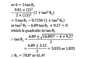
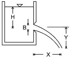
A fire-brigade man is holding a fire stream nozzle of 5 cm diameter as shown in Fig. The jet issues out with a velocity 13 m/s and strikes the window. Find the angle or angles of inclination with which the jet issues from the nozzle. What will be the amount of water falling on the window?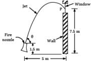
- a) θ = 78.8°; Q = 0.0255 m3/s
- b) θ = 61.9°; Q = 0.0255 m3/s
- c) Both (A) and (B)
- d) None of the above
Correct answer is option 'C'. Can you explain this answer?
A fire-brigade man is holding a fire stream nozzle of 5 cm diameter as shown in Fig. The jet issues out with a velocity 13 m/s and strikes the window. Find the angle or angles of inclination with which the jet issues from the nozzle. What will be the amount of water falling on the window?
a)
θ = 78.8°; Q = 0.0255 m3/s
b)
θ = 61.9°; Q = 0.0255 m3/s
c)
Both (A) and (B)
d)
None of the above
|
|
Zoya Sharma answered |
Corresponding to nozzle exit, the co-ordinates of the point P where the jet strikes the window are: x = 5 m and y = 7.5 − 1.5 = 6 m (i) The path of trajectory is prescribed by the equation,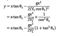
(ii) Amount of water falling on the window equals the amount delivered by the nozzle
In a two dimensional flow, the component of the velocity along the X-axis and the Y-axis are u = ax2 + bxy and v = cxy +dy2. What should be the condition for the flow field to be continuous? - a)(a + b)x + (c + d)y = 0
- b)(a + c)x + (b + d)y = 0
- c)(2a + b)x + (c + 2d)y = 0
- d)(2a + c)x + (b + 2d)y = 0
Correct answer is option 'D'. Can you explain this answer?
In a two dimensional flow, the component of the velocity along the X-axis and the Y-axis are u = ax2 + bxy and v = cxy +dy2. What should be the condition for the flow field to be continuous?
a)
(a + b)x + (c + d)y = 0
b)
(a + c)x + (b + d)y = 0
c)
(2a + b)x + (c + 2d)y = 0
d)
(2a + c)x + (b + 2d)y = 0
|
|
Muskaan Sen answered |
Explanation: The condition for the flow field to be continuous is:
2ax + cx + by + 2dy = 0
(2a + c)x + (b + 2d)y = 0.
2ax + cx + by + 2dy = 0
(2a + c)x + (b + 2d)y = 0.
Water flows from a large tank, open to the atmosphere, through a 10 cm diameter well rounded aperture in its side. The free surface of water is 5 m above the centerline of the aperture. Calculate the velocity of jet issuing from the hole and the discharge. If a 90° elbow is placed at exit from the aperture, determine how high the water will reach.- a) 0.07 m3/s, 5 m
- b) 5 m3/s, 0.7 m
- c) 0.7 m3/s, 5 m
- d) 0.5 m3/s, 0.7 m
Correct answer is option 'A'. Can you explain this answer?
Water flows from a large tank, open to the atmosphere, through a 10 cm diameter well rounded aperture in its side. The free surface of water is 5 m above the centerline of the aperture. Calculate the velocity of jet issuing from the hole and the discharge. If a 90° elbow is placed at exit from the aperture, determine how high the water will reach.
a)
0.07 m3/s, 5 m
b)
5 m3/s, 0.7 m
c)
0.7 m3/s, 5 m
d)
0.5 m3/s, 0.7 m
|
|
Lavanya Menon answered |
(i)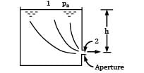
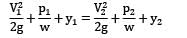
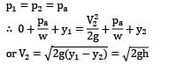
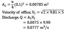
Apply Bernoulli’s equation between a point (1) on the water surface and a point (2) downstream from the aperture.
Velocity V1 on the water surface in the reservoir is practically zero because the cross sectional area of the tank is much greater than that of the aperture.
Pressure is atmospheric both at the free water surface and at the center line of the jet
i.e., velocity of efflux from the aperture is equal to the velocity of the free fall from the surface of the reservoir. This is known as Torricelli’s Theorem.
Now: h = 5 m
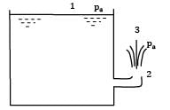
(ii)
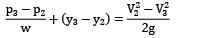
Apply Bernoulli’s equation between point 2 and 3; the point 3 refers to the position of maximum elevation of the jet.
(iii) Pressure is atmospheric both at points 2 and 3, i.e., P2 = P3 = Pa
Thus if there are no losses, the water jet would reach the initial level of water in the tank and this is the height to which the water may be sprayed.
Which one of the follflowing is correct?- a)Darcy-Weisbach’s formula is generally used for head loss in flow through both pipes and open channels
- b)Chezy’s formula is generally used for head loss in flow through both pipes and open channels
- c)Darcy-Weisbach’s formula is generally used for head loss in flow through both pipes and Chezy’s formula for open channels
- d)Chezy’s formula is generally used for head loss in flow through both pipes and Darcy-Weisbach’s formula for open channels
Correct answer is option 'C'. Can you explain this answer?
Which one of the follflowing is correct?
a)
Darcy-Weisbach’s formula is generally used for head loss in flow through both pipes and open channels
b)
Chezy’s formula is generally used for head loss in flow through both pipes and open channels
c)
Darcy-Weisbach’s formula is generally used for head loss in flow through both pipes and Chezy’s formula for open channels
d)
Chezy’s formula is generally used for head loss in flow through both pipes and Darcy-Weisbach’s formula for open channels
|
|
Janhavi Datta answered |
Formula is used to calculate the pressure drop in pipes.b)Darcy-Weisbach formula is used to calculate the flow rate in pipes.
a) Darcy-Weisbach formula is used to calculate the pressure drop in pipes.
a) Darcy-Weisbach formula is used to calculate the pressure drop in pipes.
A fireman holds a water hose ending into a nozzle that issues a 20 mm diameter jet of water. If the pressure of water in the 60 mm diameter hose is 700 kPa, find the force (in N) experienced by the fireman.Correct answer is 'Range: 1580 to 1590'. Can you explain this answer?
A fireman holds a water hose ending into a nozzle that issues a 20 mm diameter jet of water. If the pressure of water in the 60 mm diameter hose is 700 kPa, find the force (in N) experienced by the fireman.
|
|
Tanvi Shah answered |
Impulse momentum equation gives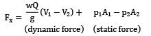
Considering the center line of flow passing along the x-axis.
Since the nozzle discharges into atmosphere P2 = 0 and for horizontal arrangement y1 = y2
= −394.85 + 1978.2
= 1583.36 N
The water exerts a force of 1583.35 N on the nozzle and it acts in a direction, opposite to direction of flow. An equal and opposite force will be exerted by the nozzle on the fluid mass.
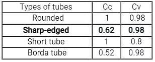
The value of the coefficient of velocity for sharp edged orifices, is- a)0.41
- b)0.98
- c)0.85
- d)0.66
Correct answer is option 'B'. Can you explain this answer?
The value of the coefficient of velocity for sharp edged orifices, is
a)
0.41
b)
0.98
c)
0.85
d)
0.66
|
|
Sanvi Kapoor answered |
Coefficient of velocity:
It is defined as the ratio of the actual velocity of the jet at veena contracta V to the theoretical velocity Vth.
Experimentally it is determine by using the following relation
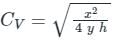
where x= Horizontal distance
y= vertical distance
h= constant head water
Generally the value of Cv varies from 0.95 to .99 for different orifices depending upon their size, shape, head etc. for sharp edged orifices the value of Cv is 0.98.
It is defined as the ratio of the actual velocity of the jet at veena contracta V to the theoretical velocity Vth.
Experimentally it is determine by using the following relation
where x= Horizontal distance
y= vertical distance
h= constant head water
Generally the value of Cv varies from 0.95 to .99 for different orifices depending upon their size, shape, head etc. for sharp edged orifices the value of Cv is 0.98.
An open tank contains water upto a depth of 350 cm and above it an oil of specific gravity 0.65 for a depth of 2.5 m. Find the pressure intensity at the extreme bottom of the tank.Correct answer is '5.026 - 5.030'. Can you explain this answer?
An open tank contains water upto a depth of 350 cm and above it an oil of specific gravity 0.65 for a depth of 2.5 m. Find the pressure intensity at the extreme bottom of the tank.
|
|
Lavanya Menon answered |
p = (specific gravity of water* height of water + specific gravity of oil* height of oil) * 9.81
= 5.027 N/cm2.
= 5.027 N/cm2.
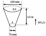
A vertical water pipe, 1.5 m long, diverges from 75 mm diameter at the bottom to 150 mm diameter at the top and the rate of flow is 50 L/s upwards. If the pressure at the bottom end is 150 kN/m2 , the pressure at the top will be nearly(!) 195.2 kN⁄m2- a) 191.4 kN⁄m2
- b) 187.6 kN⁄m2
- c) 183.8 kN⁄m2
Correct answer is option 'A'. Can you explain this answer?
A vertical water pipe, 1.5 m long, diverges from 75 mm diameter at the bottom to 150 mm diameter at the top and the rate of flow is 50 L/s upwards. If the pressure at the bottom end is 150 kN/m2 , the pressure at the top will be nearly
(!) 195.2 kN⁄m2
a)
191.4 kN⁄m2
b)
187.6 kN⁄m2
c)
183.8 kN⁄m2
|
|
Lavanya Menon answered |
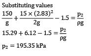
p1 = 150 × 103
Q = 50 L/s
Applying continuity equation at 1 and 2
V1 x A1 = V2 x A2
V1/V2 = (150/75)2
V1=4 V2
Applying Bernoulli equation and 1 and 2
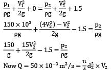
V2 = 2.83m/sec
For incompressible fluid flow, if area reduces then what is the effect on the velocity.- a)increases
- b)decreases
- c)first increases then decreases
- d)first decreases then increases
Correct answer is option 'A'. Can you explain this answer?
For incompressible fluid flow, if area reduces then what is the effect on the velocity.
a)
increases
b)
decreases
c)
first increases then decreases
d)
first decreases then increases
|
|
Partho Jain answered |
Explanation: According to continuity equation,
Area × velocity = constant
Hence, as area decreases velocity increases.
Area × velocity = constant
Hence, as area decreases velocity increases.
A venturi meter is preferable to orifice meter because- a)it is cheaper
- b)it is more convenient
- c)energy loss is less
- d)it is easy to assemble
Correct answer is option 'C'. Can you explain this answer?
A venturi meter is preferable to orifice meter because
a)
it is cheaper
b)
it is more convenient
c)
energy loss is less
d)
it is easy to assemble
|
|
Aniket Mehta answered |
A venturi meter is preferable to an orifice meter because the energy loss is less in a venturi meter compared to an orifice meter. The energy loss in a flow measurement device is an important consideration as it affects the accuracy and efficiency of the measurement.
Energy Loss in Venturi Meter:
1. The venturi meter operates on the principle of Bernoulli's equation, which states that the total energy of a fluid is constant along a streamline. This means that the sum of the potential energy, kinetic energy, and static pressure remains constant.
2. In a venturi meter, the fluid flowing through a converging section experiences an increase in velocity and a decrease in pressure. This change in velocity and pressure allows for the measurement of the flow rate.
3. The gradual change in velocity and pressure in a venturi meter minimizes energy losses due to turbulence and friction. The smooth transition from the converging section to the throat and then to the diverging section helps maintain the total energy of the fluid.
Energy Loss in Orifice Meter:
1. An orifice meter consists of a plate with a hole (orifice) inserted in a pipeline. The fluid passing through the orifice experiences a reduction in pressure and an increase in velocity.
2. However, due to the sudden contraction and expansion of the fluid flow, energy losses occur in the form of turbulence and eddies. These losses result in a decrease in the accuracy and efficiency of the flow measurement.
Comparison:
1. The venturi meter has a smoother flow path compared to the orifice meter, reducing the energy losses. This leads to higher accuracy and efficiency in flow measurement.
2. The orifice meter is cheaper and easier to assemble compared to a venturi meter. However, the energy loss in an orifice meter can be significant, impacting the reliability of the measurement.
Conclusion:
In conclusion, a venturi meter is preferable to an orifice meter because it has lower energy losses. While the orifice meter may be cheaper and easier to assemble, the accuracy and efficiency of the flow measurement are compromised due to higher energy losses. Therefore, in applications where accuracy is crucial, such as in industrial processes or water supply systems, a venturi meter is the preferred choice.
If a liquid enters a pipe of diameter d with a velocity v, what will it’s velocity at the exit if the diameter reduces to 0.5d?- a)v
- b)0.5v
- c)2v
- d)4v
Correct answer is option 'D'. Can you explain this answer?
If a liquid enters a pipe of diameter d with a velocity v, what will it’s velocity at the exit if the diameter reduces to 0.5d?
a)
v
b)
0.5v
c)
2v
d)
4v
|
|
Siddharth Bajaj answered |
Explanation: According to the Continuity Equation,

where a represents flow area, v represents flow velocity, i is for inlet conditions and o is for outlet conditions.

Hence option (D) is correct
For video explanation of Continuity Equation click on the link given below"
The frictional resistance for fluids in motion varies- a)slightly with temperature for both laminar and turbulent flows
- b)considerably with temperature for both laminar and turbulent flows
- c)slightly with temperature for laminar flow and considerably with temperature for turbulent flow
- d)considerably with temperature for laminar flow and slightly with temperature for turbulent flow
Correct answer is option 'D'. Can you explain this answer?
The frictional resistance for fluids in motion varies
a)
slightly with temperature for both laminar and turbulent flows
b)
considerably with temperature for both laminar and turbulent flows
c)
slightly with temperature for laminar flow and considerably with temperature for turbulent flow
d)
considerably with temperature for laminar flow and slightly with temperature for turbulent flow
|
|
Partho Jain answered |
Explanation: According to the laws of fluid friction, the frictional resistance for fluids in motion varies considerably with temperature for laminar flow and slightly with temperature for turbulent flow.
Hydraulic gradient line takes into consideration- a)potential and kinetic heads only
- b)potential and pressure heads only
- c)kinetic and pressure heads only
- d)potential, kinetic and pressure heads
Correct answer is option 'B'. Can you explain this answer?
Hydraulic gradient line takes into consideration
a)
potential and kinetic heads only
b)
potential and pressure heads only
c)
kinetic and pressure heads only
d)
potential, kinetic and pressure heads
|
|
Partho Jain answered |
Explanation: HGL is obtained by plotting piezometric head at various points along the axis of the pipe.
Hp = P ⁄ γ + z
where Hp is the piezometric head, P ⁄ γ is the pressure head and z is the potential head.
Hp = P ⁄ γ + z
where Hp is the piezometric head, P ⁄ γ is the pressure head and z is the potential head.
The time taken to empty the tank is independent of Cd but depends only on the height and acceleration due to gravity.- a)True
- b)False
Correct answer is option 'B'. Can you explain this answer?
The time taken to empty the tank is independent of Cd but depends only on the height and acceleration due to gravity.
a)
True
b)
False
|
|
Aarav Chauhan answered |
Explanation: The time taken to empty the tank is dependent on Cd as well as depends only on the height and acceleration due to gravity.
Chapter doubts & questions for Fluid Dynamics - 6 Months Preparation for GATE Civil Engg 2025 is part of Civil Engineering (CE) exam preparation. The chapters have been prepared according to the Civil Engineering (CE) exam syllabus. The Chapter doubts & questions, notes, tests & MCQs are made for Civil Engineering (CE) 2025 Exam. Find important definitions, questions, notes, meanings, examples, exercises, MCQs and online tests here.
Chapter doubts & questions of Fluid Dynamics - 6 Months Preparation for GATE Civil Engg in English & Hindi are available as part of Civil Engineering (CE) exam.
Download more important topics, notes, lectures and mock test series for Civil Engineering (CE) Exam by signing up for free.
6 Months Preparation for GATE Civil Engg
488 videos|1261 docs|878 tests
|
|
© EduRev
|
Education Revolution
|


|


Signup to see your scores
go up
within 7 days!
within 7 days!
Takes less than 10 seconds to signup