


All Exams >
Mechanical Engineering >
Topicwise Question Bank for Mechanical Engineering >
All Questions
All questions of Manufacturing Engineering for Mechanical Engineering Exam
My grandpa __________ (sleep) for three hours when I woke him up.Correct answer is 'had been sleeping'. Can you explain this answer?
My grandpa __________ (sleep) for three hours when I woke him up.
|
|
Saumya Dasgupta answered |
Explanation:
The correct answer to the given sentence is "had been sleeping" because it is in past perfect continuous tense. This tense is used to describe an action that was ongoing in the past before another action took place.
Here is a detailed explanation of the sentence:
- The sentence is in the past tense, as indicated by the word "woke" which is the past tense of "wake".
- The action of sleeping started before the moment of waking up and continued until that moment.
- The past perfect continuous tense is formed using the auxiliary verb "had" in the past perfect tense, the main verb "been" in the present participle form, and the main verb "sleep" in the base form with "-ing" added to the end.
- The sentence can be rephrased as "By the time I woke him up, he had been sleeping for three hours."
- The use of past perfect continuous tense emphasizes the duration of the action of sleeping that had been happening before the moment of waking up.
In summary, the correct answer "had been sleeping" indicates that the action of sleeping had started before the moment of waking up and had been ongoing for a duration of three hours until that moment.

Stroke of a shaping machine is 250 mm. It makes 30 double strokes per minute. Overall average speed of operation is- a)3.75 m/min
- b)5.0 m/min
- c)7.5 m/min
- d)15.0 m/min
Correct answer is option 'C'. Can you explain this answer?
Stroke of a shaping machine is 250 mm. It makes 30 double strokes per minute. Overall average speed of operation is
a)
3.75 m/min
b)
5.0 m/min
c)
7.5 m/min
d)
15.0 m/min

|
Shraddha Datta answered |
Given data:
Stroke of a shaping machine = 250 mm
Number of double strokes per minute = 30
To find: Overall average speed of operation
Formula used:
Overall average speed of operation = (length of stroke x number of double strokes per minute) / 1000
Calculation:
Substituting the given values in the formula, we get
Overall average speed of operation = (250 x 30) / 1000
= 7.5 m/min
Therefore, the correct answer is option C, i.e., 7.5 m/min.
Explanation:
The overall average speed of operation of a shaping machine is the distance traveled by the tool in one minute. As the machine makes 30 double strokes per minute, the tool travels a distance of 250 mm x 30 = 7500 mm or 7.5 m in one minute. Hence, the overall average speed of operation is 7.5 m/min.
Using the Taylor equation for tool life and letting n = 0.5 and C= 400, calculate the percentage increase in tool life when the cutting speed is reduced by 50%.- a)100%
- b)No change
- c)400%
- d)300%
Correct answer is option 'D'. Can you explain this answer?
Using the Taylor equation for tool life and letting n = 0.5 and C= 400, calculate the percentage increase in tool life when the cutting speed is reduced by 50%.
a)
100%
b)
No change
c)
400%
d)
300%
|
|
Vaibhav Khanna answered |
Taylor Equation for Tool Life:
The Taylor equation is used to determine the relationship between cutting speed and tool life. The equation is as follows:
VT^n = C
where,
V = cutting speed
T = tool life
n, C = constants
Calculating the Percentage Increase in Tool Life:
Given, n = 0.5 and C = 400
Let's assume the initial cutting speed is V1 and the corresponding tool life is T1. When the cutting speed is reduced by 50%, the new cutting speed becomes V2 = V1/2.
Using the Taylor equation, we can find the new tool life T2.
T1 = C/V1^n
T2 = C/V2^n
= C/(V1/2)^n
= C/(2^n * V1^n)
= (1/2^n) * (C/V1^n)
= (1/2^(0.5)) * T1
= 0.707 * T1
Therefore, the new tool life T2 is 0.707 times the initial tool life T1.
The percentage increase in tool life is given by:
((T2 - T1)/T1) * 100
= ((0.707T1 - T1)/T1) * 100
= -29.3%
However, we need to calculate the percentage increase in tool life when the cutting speed is reduced by 50%. This can be found as follows:
Percentage increase in tool life = |((T2 - T1)/T1) * 100|
= |((-0.293) * 100)|
= 29.3%
Therefore, the percentage increase in tool life when the cutting speed is reduced by 50% is 29.3%. This is option 'D'.
Chills are used in casting moulds to- a)achieve directional solidification
- b)reduce possibility of blow holes
- c)reduce the freezing time
- d)increase the smoothness of cost surface
Correct answer is option 'A'. Can you explain this answer?
Chills are used in casting moulds to
a)
achieve directional solidification
b)
reduce possibility of blow holes
c)
reduce the freezing time
d)
increase the smoothness of cost surface
|
|
Jyoti Deshpande answered |
Chills are placed around the core and it is used to achieve directional solidification.
An improper riser may give rise to a defect called- a)Shift
- b)Shrinkage cavity
- c)Penetration
- d)Misrun
Correct answer is option 'B'. Can you explain this answer?
An improper riser may give rise to a defect called
a)
Shift
b)
Shrinkage cavity
c)
Penetration
d)
Misrun
|
|
Zoya Sharma answered |
An improper riser may give rise to a defect called shrinkage cavity
Tandem drawing of wires and tubes is necessary because
- a)annealing is needed between stages
- b)it is not possible to reduce at one stage
- c)surface finish improves after every drawing stage
- d)accuracy in dimensions is not possible otherwise
Correct answer is option 'A'. Can you explain this answer?
Tandem drawing of wires and tubes is necessary because
a)
annealing is needed between stages
b)
it is not possible to reduce at one stage
c)
surface finish improves after every drawing stage
d)
accuracy in dimensions is not possible otherwise

|
Crack Gate answered |
Tandem drawing is the drawing force of the process through two dies in tandem was evaluated by being compared with the drawing force of a conventional drawing process.
Tandem drawing of wires and tubes is necessary because annealing is needed between stages.
Tandem drawing of wires and tubes is necessary because annealing is needed between stages.
Which statement is true for EDM?
1. MRR increases with decreasing resistance.
2. MRR increases with decreasing capacitance.
3. MRR increases with increasing capacitance.
4. MRR increases with optimum spark gap then decreases with increasing spark gap.- a)1, 2, 3 and 4
- b)1, 2 and 3
- c)1, 3 and 4
- d)1, 2 and 4
Correct answer is option 'A'. Can you explain this answer?
Which statement is true for EDM?
1. MRR increases with decreasing resistance.
2. MRR increases with decreasing capacitance.
3. MRR increases with increasing capacitance.
4. MRR increases with optimum spark gap then decreases with increasing spark gap.
1. MRR increases with decreasing resistance.
2. MRR increases with decreasing capacitance.
3. MRR increases with increasing capacitance.
4. MRR increases with optimum spark gap then decreases with increasing spark gap.
a)
1, 2, 3 and 4
b)
1, 2 and 3
c)
1, 3 and 4
d)
1, 2 and 4
|
|
Arshiya Dey answered |
Hence for higher MRR higher current and higher atomic weight is required.
When machining a hard and brittle metal like cast iron, the type of chips produced is- a)continuous chips
- b)discontinuous chips
- c)fine chips
- d)continuous chips with built-up edge
Correct answer is option 'B'. Can you explain this answer?
When machining a hard and brittle metal like cast iron, the type of chips produced is
a)
continuous chips
b)
discontinuous chips
c)
fine chips
d)
continuous chips with built-up edge
|
|
Avinash Sharma answered |
Discontinuous chips are formed when machining brittle material at iow speed.
The portion of tool on which cutting edge is formed is known as- a)Shank
- b)Flank
- c)Face
- d)Nose
Correct answer is option 'A'. Can you explain this answer?
The portion of tool on which cutting edge is formed is known as
a)
Shank
b)
Flank
c)
Face
d)
Nose
|
|
Akshat Mehta answered |
Shank is called man body of cutting tool in which cutting edge is formed.

Which of the following gating ratio represents pressurised gating systems?- a)1 : 1 : 2
- b)1 : 2 : 1
- c)1 : 2 : 3
- d)1 : 3 : 3
Correct answer is option 'B'. Can you explain this answer?
Which of the following gating ratio represents pressurised gating systems?
a)
1 : 1 : 2
b)
1 : 2 : 1
c)
1 : 2 : 3
d)
1 : 3 : 3
|
|
Avinash Sharma answered |
Gating ratio = Sprue area: Runner area: Ingate area
If total ingate area is not greater than the area of sprue, gating systems are known as pressurised gating system.
Option (a), (c) and (d) represents unpressurized gating system.
If total ingate area is not greater than the area of sprue, gating systems are known as pressurised gating system.
Option (a), (c) and (d) represents unpressurized gating system.
Which of the following materials requires highest shrinkage allowance?- a)Aluminium
- b)Gray cast iron
- c)Steel
- d)Brass
Correct answer is option 'C'. Can you explain this answer?
Which of the following materials requires highest shrinkage allowance?
a)
Aluminium
b)
Gray cast iron
c)
Steel
d)
Brass
|
|
Kalyan Chakraborty answered |
Shrinkage allowance is the difference in dimensions between the pattern and the final casting due to the shrinkage of the metal during solidification. The amount of shrinkage allowance required is dependent on the material being used for casting.
Explanation:
Steel has the highest shrinkage allowance among the given materials. This is due to the following reasons:
1. High melting point: Steel has a high melting point compared to other materials. This means that it takes longer for the metal to cool and solidify, resulting in more shrinkage.
2. High carbon content: Steel has a higher carbon content than other materials. Carbon is a strong carbide former, which can lead to a reduction in the solidification range of steel, resulting in more shrinkage.
3. Low thermal conductivity: Steel has a lower thermal conductivity than other materials. This means that heat is retained for a longer time, resulting in a longer solidification time and more shrinkage.
4. High density: Steel has a higher density than other materials. This means that it will shrink more during solidification.
Therefore, steel requires the highest shrinkage allowance among the given materials.
Consider the following materials:
1. Copper
2. Tungsten
3. Molybdenum
4. Aluminium
Which of the above material is used as wire material in wire-EDM process?- a)1 and 4
- b)2 and 3
- c)1, 2 and 3
- d)2, 3 and 4
Correct answer is option 'C'. Can you explain this answer?
Consider the following materials:
1. Copper
2. Tungsten
3. Molybdenum
4. Aluminium
Which of the above material is used as wire material in wire-EDM process?
1. Copper
2. Tungsten
3. Molybdenum
4. Aluminium
Which of the above material is used as wire material in wire-EDM process?
a)
1 and 4
b)
2 and 3
c)
1, 2 and 3
d)
2, 3 and 4
|
|
Prasath Sundaram answered |
Aluminum is not a strongest materials to compare these three material so it not suitable for wire material
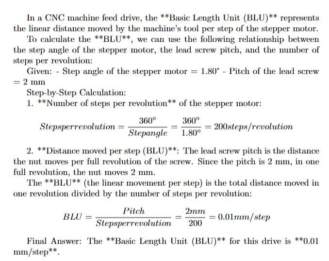
The following device is used for transmitting energy in CNC machine tools:- a)pulley and belt
- b)gears
- c)screw and nut assembly
- d)recirculating ball screw and nut assembly
Correct answer is option 'D'. Can you explain this answer?
The following device is used for transmitting energy in CNC machine tools:
a)
pulley and belt
b)
gears
c)
screw and nut assembly
d)
recirculating ball screw and nut assembly
|
|
Anmol Saini answered |
Conventional lead screw and its nut assembly is not suitable for CNC machine tools because of its lesser power transmitting capacity, lesser accuracy due to backlash and higher frictional forces. To avoid these problems, the recirculating ball screw and nut assembly is used as energy transmitting device in CNC machining

Material removed by thermal action in- a)Abrasive-flow machining
- b)Electrochemical grinding
- c)Laser-beam machining
- d)Chemical machining
Correct answer is option 'C'. Can you explain this answer?
Material removed by thermal action in
a)
Abrasive-flow machining
b)
Electrochemical grinding
c)
Laser-beam machining
d)
Chemical machining
|
|
Rashi Chauhan answered |
Material removal by mechanical action: AJM, Low-stress grinding, USM Material removed by electrical process: Electrochemical deburring, Electrochemical grinding , Electroch emical milling , Electrochemical polishing.
Material removed by thermal process: Electron-beam machining, Electrical discharge grinding, Laser beam machining, Plasma beam machining.
Material removed by chemical process: ECM, Photochemical maching
Material removed by thermal process: Electron-beam machining, Electrical discharge grinding, Laser beam machining, Plasma beam machining.
Material removed by chemical process: ECM, Photochemical maching
Which among the following is slowest speed operation in lathe?- a)Turning
- b)Thread cutting
- c)Taper turning
- d)Knurling
Correct answer is option 'A'. Can you explain this answer?
Which among the following is slowest speed operation in lathe?
a)
Turning
b)
Thread cutting
c)
Taper turning
d)
Knurling
|
|
Samarth Chaudhary answered |
The dummy activities are used to complete the iogical sequence, but do not consume any time or resources. A dummy activity is thus a connecting link for control purpose or for maintaining uniqueness of activity.
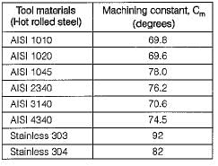
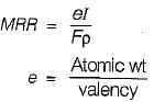
Which one of the following process conditions leads to higher MRR in ECM process?- a)Higher current, larger atomic weight
- b)Higher valency, lower current
- c)Lower atomic weight, lower valency
- d)Higher valency, lower atomic weight
Correct answer is option 'A'. Can you explain this answer?
Which one of the following process conditions leads to higher MRR in ECM process?
a)
Higher current, larger atomic weight
b)
Higher valency, lower current
c)
Lower atomic weight, lower valency
d)
Higher valency, lower atomic weight
|
|
Dishani Desai answered |
In electrochemical machining (ECM) electrolyte (example NaCl or NaCIO is used).
In electrode discharge machining (ECM) dielectric (Kerosene) is used.
In ultrasonic machining abrasive slurry is used.
In electron beam machining (EBM) vacuum Is maintained to have proper kinetic energy of electron beam.
In electrode discharge machining (ECM) dielectric (Kerosene) is used.
In ultrasonic machining abrasive slurry is used.
In electron beam machining (EBM) vacuum Is maintained to have proper kinetic energy of electron beam.
Sintering time is minimum for- a)iron
- b)stainless steel
- c)alnico alloy
- d)tungsten carbides
Correct answer is option 'A'. Can you explain this answer?
Sintering time is minimum for
a)
iron
b)
stainless steel
c)
alnico alloy
d)
tungsten carbides
|
|
Sai Reddy answered |
Sintering is a process used in the manufacturing of metal parts, where powdered metal is compacted into a desired shape and then heated to a temperature below its melting point. During sintering, the metal particles are bonded together to form a solid object. The sintering time required for different materials can vary based on their properties and composition.
The correct answer for the minimum sintering time is option 'A', which is iron.
Here is an explanation of why iron has the minimum sintering time compared to the other options:
1. Iron:
- Iron has a relatively low melting point compared to other materials like stainless steel, alnico alloy, and tungsten carbides. This lower melting point allows for faster sintering because less time is required to heat the iron powder to the necessary temperature for bonding.
- Iron also has good sintering properties, meaning it can be easily compacted and bonded during the sintering process. This further reduces the required sintering time.
2. Stainless Steel:
- Stainless steel is an alloy composed of iron, chromium, and other elements. It has a higher melting point compared to pure iron, which means it requires more time to reach the sintering temperature during the heating process.
- Additionally, stainless steel has higher hardness and strength compared to iron, which can make it more difficult to deform and bond the particles during sintering. This may also increase the required sintering time.
3. Alnico Alloy:
- Alnico alloy is a type of permanent magnet alloy composed of aluminum, nickel, cobalt, and iron. It has a higher melting point compared to iron, similar to stainless steel.
- The complex composition of alnico alloy can make it more difficult to sinter compared to pure iron. The different elements in the alloy may have different melting points and sintering behaviors, requiring more time to achieve proper bonding.
4. Tungsten Carbides:
- Tungsten carbides are a group of hard and brittle materials composed of tungsten and carbon. They have a very high melting point, making them the most challenging to sinter.
- The high melting point of tungsten carbides requires a longer sintering time to reach the necessary temperature for bonding. Additionally, the hardness and brittleness of tungsten carbides can make it more difficult to deform and bond the particles during sintering.
In conclusion, the sintering time is minimum for iron compared to stainless steel, alnico alloy, and tungsten carbides. This is due to the lower melting point and better sintering properties of iron.
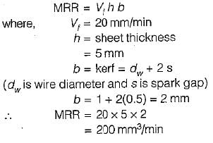
A titanium sheet of 5 mm thickness is cut by wire-cut EDM process using a wire of 1 mm diameter. A uniform spark gap of 0.5 mm on both sides of the wire is maintained during cutting operation. If the feed rate of the wire into the sheet is 20 mm/min, the material removal rate (in mm3/min) will be- a)150
- b)200
- c)300
- d)400
Correct answer is option 'B'. Can you explain this answer?
A titanium sheet of 5 mm thickness is cut by wire-cut EDM process using a wire of 1 mm diameter. A uniform spark gap of 0.5 mm on both sides of the wire is maintained during cutting operation. If the feed rate of the wire into the sheet is 20 mm/min, the material removal rate (in mm3/min) will be
a)
150
b)
200
c)
300
d)
400
|
|
Ayush Chawla answered |
Which of the following is not a sintering mechanism?- a)solid-state bonding
- b)powder rolling
- c)vapour-phase transport
- d)SPS
Correct answer is option 'B'. Can you explain this answer?
Which of the following is not a sintering mechanism?
a)
solid-state bonding
b)
powder rolling
c)
vapour-phase transport
d)
SPS
|
|
Sparsh Chakraborty answered |
Powder rolling is compacting process.
There are three sintering mechanisms:
(a) solid-state bonding or diffusion
(b) vapor-phase transport or liquid phase sintering
(c) spark sintering or spark plasma sintering (SPS)
There are three sintering mechanisms:
(a) solid-state bonding or diffusion
(b) vapor-phase transport or liquid phase sintering
(c) spark sintering or spark plasma sintering (SPS)
Tool signature is- a)a numerical method of identification of tool
- b)the plan of tool
- c)the procedure adopted for describing various tool angles
- d)used to describe the material of too
Correct answer is option 'C'. Can you explain this answer?
Tool signature is
a)
a numerical method of identification of tool
b)
the plan of tool
c)
the procedure adopted for describing various tool angles
d)
used to describe the material of too
|
|
Tanishq Rane answered |
The correct answer is option 'C', which states that tool signature is the procedure adopted for describing various tool angles. In the field of mechanical engineering, tool signature plays an important role in understanding and identifying the characteristics of a cutting tool. It consists of a set of numbers and symbols that provide information about the angles and dimensions of the tool.
The tool signature is used to describe the various angles associated with a cutting tool. These angles include:
1. Rake angle: It is the angle between the rake face of the tool and the normal to the machined surface. It determines the direction of chip flow and affects the cutting forces and tool life.
2. Relief angle: It is the angle between the flank of the tool and a line perpendicular to the machined surface. It provides clearance for the tool, reducing friction and minimizing the chance of built-up edge formation.
3. Side cutting edge angle: It is the angle between the side cutting edge of the tool and the machined surface. It determines the direction of cutting forces and affects the chip thickness and surface finish.
4. End cutting edge angle: It is the angle between the end cutting edge of the tool and the machined surface. It affects the cutting forces and surface finish.
5. Nose radius: It is the radius of curvature at the tip of the tool. It reduces the stress concentration and improves tool life.
The tool signature also includes information about the dimensions of the tool, such as the tool height, tool width, and nose radius. These dimensions are important for selecting the appropriate tool for a specific machining operation.
By using the tool signature, engineers and machinists can easily identify and select the right tool for a particular machining operation. It helps in optimizing cutting conditions, reducing tool wear, and improving productivity. Moreover, the tool signature is also useful in tool regrinding or replacement, as it provides a reference for restoring the original tool angles.
In conclusion, the tool signature is a procedure adopted for describing various tool angles. It is an essential tool in the field of mechanical engineering, providing valuable information for tool selection, optimization of cutting conditions, and tool maintenance.
While pouring molten metal in the mould of the molten metal does not appear in the riser. It indicates- a)a sound casting will be produced
- b)an obstruction between sprue and riser
- c)insufficient molten metal to fill the cavity
- d)either insufficient molten metal to fill the cavity or an obstruction between sprue and riser
Correct answer is option 'A'. Can you explain this answer?
While pouring molten metal in the mould of the molten metal does not appear in the riser. It indicates
a)
a sound casting will be produced
b)
an obstruction between sprue and riser
c)
insufficient molten metal to fill the cavity
d)
either insufficient molten metal to fill the cavity or an obstruction between sprue and riser
|
|
Anmol Saini answered |
Explanation:
When pouring molten metal into a mould, it is important to ensure that the metal fills the entire cavity without any defects or voids. The use of risers is a common technique to prevent shrinkage defects in castings. A riser is an additional volume of molten metal that is connected to the casting through a channel, and it serves as a reservoir of molten metal that can compensate for the shrinkage during solidification.
If the molten metal does not appear in the riser during pouring, it indicates that a sound casting will be produced. This is because the molten metal has completely filled the cavity without any defects or voids, and there is no need for additional molten metal from the riser. This is a desirable situation, as it indicates that the casting will have good dimensional accuracy and mechanical properties.
If the molten metal does not appear in the riser, it rules out the possibility of the other three options:
- An obstruction between sprue and riser: If there was an obstruction, the molten metal would not have been able to flow freely into the cavity, and there would be defects or voids in the casting.
- Insufficient molten metal to fill the cavity: If there was insufficient molten metal, the cavity would not have been completely filled, and there would be defects or voids in the casting.
- Either insufficient molten metal to fill the cavity or an obstruction between sprue and riser: This is a combination of the previous two options, and it is also ruled out by the absence of molten metal in the riser.
Thus, the absence of molten metal in the riser during pouring is a good sign that a sound casting will be produced.
What does hydrostatic pressure in extrusion process improve?- a)Ductility
- b)Compressive strength
- c)Brittleness
- d)Tensile strength
Correct answer is option 'A'. Can you explain this answer?
What does hydrostatic pressure in extrusion process improve?
a)
Ductility
b)
Compressive strength
c)
Brittleness
d)
Tensile strength
|
|
Kiran Basu answered |
Hydrostatic pressure increases the ductility of the material. Therefore, brittle material can be extruded bv this method.
In the tolerance specification, 25 D6 the letter D represents- a) Lower deviation
- b)Upper deviation
- c)Grade of tolerance
- d)Type of fit
Correct answer is option 'A'. Can you explain this answer?
In the tolerance specification, 25 D6 the letter D represents
a)
Lower deviation
b)
Upper deviation
c)
Grade of tolerance
d)
Type of fit
|
|
Raghav Saini answered |
6 represents grade of tolerance and since D is used for hole it represents lower deviation (d used for shaft).
The process of putting a rod through several dies of decreasing diameter is known as
- a)wire drawing
- b)stretch forming
- c)trimming
- d)rolling
Correct answer is option 'A'. Can you explain this answer?
The process of putting a rod through several dies of decreasing diameter is known as
a)
wire drawing
b)
stretch forming
c)
trimming
d)
rolling
|
|
Gaurav Kapoor answered |
Correct Answer :- A
Explanation : The process of putting a rod through several dies of decreasing diameter is known as wire drawing.
The purpose of riser is to- a)deliver molten metal into the mould cavity
- b)act as a reservoir for the molten metal
- c)feed the molten metal to the casting in order to compensate for the shrinkage
- d)deliver the molten metal from pouring basin to gate
Correct answer is option 'B'. Can you explain this answer?
The purpose of riser is to
a)
deliver molten metal into the mould cavity
b)
act as a reservoir for the molten metal
c)
feed the molten metal to the casting in order to compensate for the shrinkage
d)
deliver the molten metal from pouring basin to gate
|
|
Dipika Bose answered |
Riser in Casting Processes
Riser is an integral part of casting processes. It is a reservoir of molten metal that compensates for the shrinkage that occurs during solidification. This shrinkage can lead to various casting defects, such as porosity, shrinkage cavities, and cracks.
Purpose of Riser
The primary purpose of the riser is to feed the molten metal to the casting in order to compensate for the shrinkage. When the molten metal is poured into the mould cavity, it begins to solidify from the surface towards the centre. As the metal solidifies, it shrinks and creates a void or a cavity in the casting.
The riser compensates for this shrinkage by providing additional molten metal to the casting. The molten metal in the riser solidifies after the metal in the casting has solidified. This solidification of the riser provides an additional source of metal to compensate for the shrinkage in the casting.
Other Purposes of Riser
Apart from compensating for the shrinkage, the riser also serves other purposes in the casting processes. These include:
1. Acting as a reservoir for the molten metal: The riser acts as a reservoir for the molten metal and ensures that there is enough metal available to fill the mould cavity.
2. Providing a source of feeding: The riser provides a source of feeding to the casting by supplying additional molten metal.
3. Reducing the risk of defects: The riser reduces the risk of defects in the casting by compensating for the shrinkage and ensuring that the casting is filled with metal.
Conclusion
In summary, the primary purpose of the riser in casting processes is to compensate for the shrinkage that occurs during solidification. It provides additional molten metal to the casting to ensure that the casting is filled with metal and reduce the risk of defects.
Climb milling is chosen while machining because- a)the chip thickness increases gradually
- b)it enables the cutter to dig in and start the cut
- c)the specific power consumption is reduced
- d)better surface finish can be obtained
Correct answer is option 'C'. Can you explain this answer?
Climb milling is chosen while machining because
a)
the chip thickness increases gradually
b)
it enables the cutter to dig in and start the cut
c)
the specific power consumption is reduced
d)
better surface finish can be obtained
|
|
Kiran Basu answered |
Followings are the advantages of down or climb milling:
- cuttter tends to push the workpiece against the milling table in the downward direction thereby increasing the stability.
- the cutter has increased tool life as compared to up milling because of higher values of rake angle.
- specific power consumption is low.
- cuttter tends to push the workpiece against the milling table in the downward direction thereby increasing the stability.
- the cutter has increased tool life as compared to up milling because of higher values of rake angle.
- specific power consumption is low.
The impurities in true centrifugal casting- a)get collected at outer surface
- b)mix up thoroughly throughout
- c)get collected at the inner surface
- d)get collected in the middle portion in between inner and outer surface
Correct answer is option 'C'. Can you explain this answer?
The impurities in true centrifugal casting
a)
get collected at outer surface
b)
mix up thoroughly throughout
c)
get collected at the inner surface
d)
get collected in the middle portion in between inner and outer surface
|
|
Gaurav Kapoor answered |
The impurities in true centrifugal casting get collected in the middle portion in between the inner and outer surface. This is because of the unique nature of the centrifugal casting process, which involves the use of centrifugal force to distribute the molten metal and impurities.
Explanation:
1. The Centrifugal Casting Process:
- Centrifugal casting is a casting process that uses the principle of centrifugal force to distribute the molten metal and impurities.
- In this process, a mold is rotated at high speeds while the molten metal is poured into it.
- The centrifugal force generated by the rotation of the mold pushes the molten metal towards the outer surface of the mold, while the impurities tend to move towards the inner surface.
2. Movement of Impurities:
- As the molten metal is poured into the rotating mold, the centrifugal force acts on it, causing it to move towards the outer surface of the mold.
- At the same time, the impurities present in the molten metal also experience the centrifugal force and tend to move towards the inner surface.
- However, due to their higher density compared to the molten metal, the impurities are not able to move as easily as the molten metal.
- As a result, the impurities get trapped in the middle portion of the casting, which is in between the inner and outer surface.
3. Collection of Impurities:
- The impurities that get collected in the middle portion of the casting are typically in the form of slag, oxides, or other non-metallic contaminants.
- These impurities are undesirable in the final casting as they can weaken the material and affect its mechanical properties.
- To minimize the presence of impurities, various techniques can be used, such as the use of proper gating systems, filtering the molten metal, and controlling the pouring temperature.
In conclusion, in true centrifugal casting, the impurities get collected in the middle portion in between the inner and outer surface. This is due to the movement of the molten metal towards the outer surface under the influence of centrifugal force, while the impurities, being denser, tend to remain in the middle portion. Proper control and techniques can be employed to minimize the impurities and ensure a high-quality casting.
Blanking and drawing operations can be performed at one station of the press in the stroke of the ram in a- a)simple die
- b)progressive die
- c)combination die
- d)compound die
Correct answer is option 'C'. Can you explain this answer?
Blanking and drawing operations can be performed at one station of the press in the stroke of the ram in a
a)
simple die
b)
progressive die
c)
combination die
d)
compound die

|
Rajat Sen answered |
A combination die is same as that of a compound die with the main difference that in this non-cutting operations such as bending and forming are also included as part of the operation. Often the nomenclature compound and combination die are interchangeably used for the same type of die.
Seam welding is a- a)continuous spot welding process
- b)multi-spot welding process
- c)arc welding process
- d)process used for joining round bars
Correct answer is option 'A'. Can you explain this answer?
Seam welding is a
a)
continuous spot welding process
b)
multi-spot welding process
c)
arc welding process
d)
process used for joining round bars
|
|
Ruchi Ahuja answered |
Seam Welding Process Explanation:
Seam welding is a type of welding process that involves making a series of overlapping spot welds to form a continuous seam. Here is an explanation of why seam welding is considered a continuous spot welding process:
Continuous Spot Welding:
- Seam welding is a variation of spot welding where the electrodes move along the joint, producing a continuous weld rather than individual spot welds.
- The electrodes apply pressure and current to the workpieces, creating a series of overlapping welds along the seam.
Advantages of Seam Welding:
- Seam welding is a high-speed process that can create a leak-proof and hermetic seal along the entire length of the seam.
- It is commonly used in the automotive industry for welding fuel tanks, exhaust systems, and other components where a continuous, watertight seal is required.
Comparison with Other Welding Processes:
- Seam welding differs from arc welding processes like MIG or TIG welding, which use a continuous electrode to create a molten pool of metal that solidifies into a weld bead.
- It is also distinct from multi-spot welding processes, which involve making multiple individual spot welds at different locations along the joint.
In conclusion, seam welding is categorized as a continuous spot welding process because it involves creating a series of overlapping spot welds to form a continuous seam. This process is widely used in industries where leak-proof and continuous welds are required.
Consider the following statements: MIG welding process uses
1. Consumable electrode
2. Nonconsumable electrode
3. D.C. power supply
4. A.C. power supply
Q. Which of these statement are correct?- a)2 and 4
- b)2 and 3
- c)1 and4
- d)1and3
Correct answer is option 'D'. Can you explain this answer?
Consider the following statements: MIG welding process uses
1. Consumable electrode
2. Nonconsumable electrode
3. D.C. power supply
4. A.C. power supply
Q. Which of these statement are correct?
1. Consumable electrode
2. Nonconsumable electrode
3. D.C. power supply
4. A.C. power supply
Q. Which of these statement are correct?
a)
2 and 4
b)
2 and 3
c)
1 and4
d)
1and3
|
|
Atharva Majumdar answered |
Metal inert gas arc welding or more appropriately called as gas metal arc welding utilizes a consumable electrode. Normally DC arc welding machines are used for MIG with electrode positive.
The regulating wheel of a centreless grinder is rotating at a surface speed of 127 mm/s and is inclined at an angle of 5°, Calculate the feed rate of material past the grinding wheel. [sin5° = 0.087, cos5° = 0.996]- a)5.2 mm/s
- b)8 mm/s
- c)11 mm/s
- d)14.2 mm/s
Correct answer is option 'C'. Can you explain this answer?
The regulating wheel of a centreless grinder is rotating at a surface speed of 127 mm/s and is inclined at an angle of 5°, Calculate the feed rate of material past the grinding wheel. [sin5° = 0.087, cos5° = 0.996]
a)
5.2 mm/s
b)
8 mm/s
c)
11 mm/s
d)
14.2 mm/s
|
|
Aniket Saini answered |
Degrees. The diameter of the regulating wheel is 254 mm.
To find the rotational speed of the regulating wheel, we can use the formula:
Rotational speed = Surface speed / Circumference
The circumference of the regulating wheel can be calculated using the formula:
Circumference = π * diameter
Circumference = 3.14 * 254 mm
Circumference = 798.36 mm
Now, we can calculate the rotational speed:
Rotational speed = 127 mm/s / 798.36 mm
Rotational speed ≈ 0.159 radians/s
Therefore, the rotational speed of the regulating wheel is approximately 0.159 radians/s.
Trepanning operation is performed for- a)finishing a drilled hole
- b)trueing a hole for alignment
- c)producing large hole
- d)sizing a small hole
Correct answer is option 'C'. Can you explain this answer?
Trepanning operation is performed for
a)
finishing a drilled hole
b)
trueing a hole for alignment
c)
producing large hole
d)
sizing a small hole
|
|
Kajal Tiwari answered |
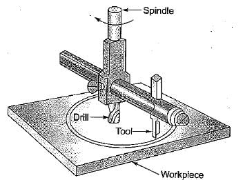
Trepanning is used to produce large size hole by removing a disk-shaped piece (core) usually from a flat plate. A hole is produced without reducing all the material removed to chip as is the case in drilling.


Consider the following ingredients used in moulding
1. Dry silica sand
2. Clay
3. Phenol formaldehyde
4. Sodium silicate
Q. These used for shell moulding include- a)1, 2 and 4
- b)2, 3 and 4
- c)1 and 3
- d)1, 2, 3 and 4
Correct answer is option 'C'. Can you explain this answer?
Consider the following ingredients used in moulding
1. Dry silica sand
2. Clay
3. Phenol formaldehyde
4. Sodium silicate
Q. These used for shell moulding include
1. Dry silica sand
2. Clay
3. Phenol formaldehyde
4. Sodium silicate
Q. These used for shell moulding include
a)
1, 2 and 4
b)
2, 3 and 4
c)
1 and 3
d)
1, 2, 3 and 4

|
Telecom Tuners answered |
- Dry silica sand: This is the primary base material in shell molding. It provides the structure and strength to the mold.
- Phenol formaldehyde: This is a thermosetting resin binder used in shell molding. When mixed with a catalyst, it reacts and cures to form a strong bond between the sand grains, creating the shell.
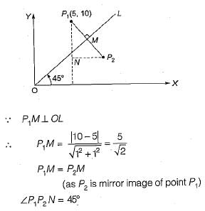
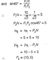
In a CAD package, mirror image of a 2D point P(5, 10) is to be obtained about a line which passes through the origin and makes an angle of 450 counterclockwise with the X-axis. The coordinates of the transformed point will be- a)(7.5, 5)
- b)(10, 5)
- c)(7.5, -5)
- d)(10, -5)
Correct answer is option 'B'. Can you explain this answer?
In a CAD package, mirror image of a 2D point P(5, 10) is to be obtained about a line which passes through the origin and makes an angle of 450 counterclockwise with the X-axis. The coordinates of the transformed point will be
a)
(7.5, 5)
b)
(10, 5)
c)
(7.5, -5)
d)
(10, -5)
|
|
Anmol Roy answered |
Which is not the application of forging?
- a)Rail sections
- b)Steel balls of ball bearings
- c)Brake pedal of an automobile
- d)Both A and B
Correct answer is option 'D'. Can you explain this answer?
Which is not the application of forging?
a)
Rail sections
b)
Steel balls of ball bearings
c)
Brake pedal of an automobile
d)
Both A and B
|
|
Vaibhav Khanna answered |
Rail sections are formed by rolling process and steel balls of ball bearings are formed by cold heading process.
Which one of the following machining process has contact between tool and work?- a)EDM
- b)ECM
- c)USM
- d)PAM
Correct answer is option 'C'. Can you explain this answer?
Which one of the following machining process has contact between tool and work?
a)
EDM
b)
ECM
c)
USM
d)
PAM
|
|
Bhavya Ahuja answered |
In USM (Ultrasonic machining) some kind of abrasive slurry is used and there is hammering action between tool and workpiece.
A small bore is designated as 25H7. The lower (minimum) and upper (maximum) limits of the bore are 25.000 mm and 25.021 mm, respectively. When the bore is designated as 25H8, then the upper (maximum) limit is 25.033 mm. When the bore is designated as 25H6, then the upper (maximum) limit of the bore (in mm) is- a)25.001
- b)25.005
- c)25.009
- d)25.013
Correct answer is option 'D'. Can you explain this answer?
A small bore is designated as 25H7. The lower (minimum) and upper (maximum) limits of the bore are 25.000 mm and 25.021 mm, respectively. When the bore is designated as 25H8, then the upper (maximum) limit is 25.033 mm. When the bore is designated as 25H6, then the upper (maximum) limit of the bore (in mm) is
a)
25.001
b)
25.005
c)
25.009
d)
25.013
|
|
Anand Kumar answered |
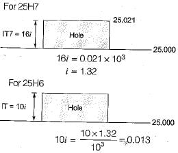
i.e. upper limit of bore = 25.013
The process in which the material removal rate is governed by Faraday law is- a)ECM
- b)EDM
- c)Abrasive jet machining
- d)Laser beam welding
Correct answer is option 'C'. Can you explain this answer?
The process in which the material removal rate is governed by Faraday law is
a)
ECM
b)
EDM
c)
Abrasive jet machining
d)
Laser beam welding
|
|
Pranavi Choudhury answered |
The metal removal by high frequency electric current is sent by ultrasonic oscillator to ultrasonic transducer. Transducer convert electrical energy into mechanical vibration and hammering action of abrasive particles remove metal.
Which of the following materials has more shrinkage allowances- a)Cl
- b)Lead
- c)Brass
- d)Aluminium alloy
Correct answer is option 'C'. Can you explain this answer?
Which of the following materials has more shrinkage allowances
a)
Cl
b)
Lead
c)
Brass
d)
Aluminium alloy
|
|
Amrita Chauhan answered |
Shrinkage Allowance in Materials
Introduction
Shrinkage allowance is the amount of additional material that needs to be added to a casting pattern to compensate for the shrinkage that occurs during the solidification and cooling process. The shrinkage allowance ensures that the final casting dimensions are accurate and match the desired specifications. Different materials have different shrinkage rates, which is why different shrinkage allowances are required for different materials.
Explanation
Among the materials mentioned in the options (Cl, Lead, Brass, and Aluminium alloy), the material with the highest shrinkage allowance is Brass.
Shrinkage Allowance Factors
Several factors influence the shrinkage allowance in a material, including:
1. Cooling rate: Faster cooling rates tend to increase shrinkage.
2. Solidification time: Longer solidification times lead to higher shrinkage.
3. Alloy composition: Different alloy compositions can result in varying shrinkage rates.
Shrinkage Allowance Comparison
Let's analyze the shrinkage allowances for each material:
1. Cl (Chlorine)
Chlorine is not a casting material but a chemical element. Therefore, it does not have a shrinkage allowance.
2. Lead
Lead is a soft and malleable material with a relatively low melting point. It exhibits minimal shrinkage during the cooling process. Therefore, the shrinkage allowance for lead is relatively low compared to other materials.
3. Brass
Brass is an alloy composed of copper and zinc. It has a higher melting point compared to lead. Due to the different thermal properties of copper and zinc, brass experiences a significant amount of shrinkage during cooling. Consequently, a larger shrinkage allowance is required for brass castings.
4. Aluminium Alloy
Aluminium alloys are widely used in various industries due to their lightweight and excellent mechanical properties. They have a relatively low shrinkage rate compared to materials like brass. Therefore, the shrinkage allowance for aluminium alloy castings is lower compared to brass.
Conclusion
Among the materials mentioned in the options, brass has the highest shrinkage allowance. This is because brass, being an alloy of copper and zinc, experiences significant shrinkage during the cooling process. It is important to consider the shrinkage allowance when designing casting patterns to ensure accurate final dimensions in the castings.
Nose radius is expressed in- a)Degree
- b)Radian
- c)mm
- d)Steradian
Correct answer is option 'C'. Can you explain this answer?
Nose radius is expressed in
a)
Degree
b)
Radian
c)
mm
d)
Steradian
|
|
Sparsh Chakraborty answered |
Nose radius is expressed in mm.
Blanking and piercing operation can be performed simultaneously in- a)simple die
- b)complex die
- c)compound die
- d)combination of several process
Correct answer is option 'C'. Can you explain this answer?
Blanking and piercing operation can be performed simultaneously in
a)
simple die
b)
complex die
c)
compound die
d)
combination of several process
|
|
Raj Kumar answered |
In compound die, multiple operation can be Derformed in single stroke and sinaie operation.
Generally washers are made by this method.
Generally washers are made by this method.
In which of the following milling operation cutter is rotated in the same direction of travel of work piece- a)Up milling
- b)Down milling
- c)Face milling
- d)End millingin
Correct answer is option 'B'. Can you explain this answer?
In which of the following milling operation cutter is rotated in the same direction of travel of work piece
a)
Up milling
b)
Down milling
c)
Face milling
d)
End millingin
|
|
Nitin Joshi answered |
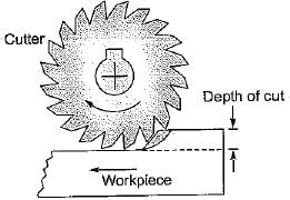
In down milling, also called climb milling, the feed direction of the workpiece is same as that of the cutter rotation.
Chapter doubts & questions for Manufacturing Engineering - Topicwise Question Bank for Mechanical Engineering 2025 is part of Mechanical Engineering exam preparation. The chapters have been prepared according to the Mechanical Engineering exam syllabus. The Chapter doubts & questions, notes, tests & MCQs are made for Mechanical Engineering 2025 Exam. Find important definitions, questions, notes, meanings, examples, exercises, MCQs and online tests here.
Chapter doubts & questions of Manufacturing Engineering - Topicwise Question Bank for Mechanical Engineering in English & Hindi are available as part of Mechanical Engineering exam.
Download more important topics, notes, lectures and mock test series for Mechanical Engineering Exam by signing up for free.
Topicwise Question Bank for Mechanical Engineering
45 videos|314 tests
|
|
© EduRev
|
Education Revolution
|


|


Signup to see your scores
go up within 7 days!
Access 1000+ FREE Docs, Videos and Tests
Takes less than 10 seconds to signup