


All Exams >
Mechanical Engineering >
GATE Mechanical (ME) Mock Test Series 2026 >
All Questions
All questions of Strength of Materials (SOM) for Mechanical Engineering Exam
The deformation of a bar under its own weight as compared to that when subjected to a direct axial load equal to its own weight will be:- a)The same
- b)One-fourth
- c)Half
- d)Double
Correct answer is option 'C'. Can you explain this answer?
The deformation of a bar under its own weight as compared to that when subjected to a direct axial load equal to its own weight will be:
a)
The same
b)
One-fourth
c)
Half
d)
Double
|
|
Janani Reddy answered |
Elongation of bar due to its own weight=Pl/2AE
Elongation of bar due to axial load=Pl/AE
Now comparing both..we will take the ratio.. (Pl/2AE)÷(Pl/AE)=1/2...i.e half

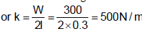
A uniform stiff rod of length 300 mm and having a weight of 300 N is pivoted at one end and connected to a spring at the other end. For keeping the rod vertical in a stable position the minimum value of spring constant K needed is: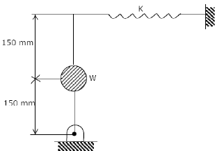
- a)300 N/m
- b)400N/m
- c)500N/m
- d)1000 N/m
Correct answer is option 'C'. Can you explain this answer?
A uniform stiff rod of length 300 mm and having a weight of 300 N is pivoted at one end and connected to a spring at the other end. For keeping the rod vertical in a stable position the minimum value of spring constant K needed is:
a)
300 N/m
b)
400N/m
c)
500N/m
d)
1000 N/m

|
Manish Aggarwal answered |
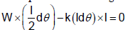
Inclined it to a very low angle, dθ
For equilibrium taking moment about „hinge‟
Which point on the stress strain curve occurs after proportionality limit?
- a)Upper yield point
- b)Lower yield point
- c)Elastic limit
- d)Ultimate point
Correct answer is option 'C'. Can you explain this answer?
Which point on the stress strain curve occurs after proportionality limit?
a)
Upper yield point
b)
Lower yield point
c)
Elastic limit
d)
Ultimate point
|
|
Anjali Sengupta answered |
A stress-strain curve represents the relationship between the stress applied to a material and the resulting strain (deformation) experienced by the material. The curve can be divided into several regions, each corresponding to a different behavior of the material under stress.
1. Proportionality limit: This is the region where the stress-strain curve is linear, and the material follows Hooke's Law, which states that the stress is proportional to the strain. In this region, the material will return to its original shape and size when the stress is removed.
2. Elastic limit: This is the point on the stress-strain curve immediately after the proportionality limit. Up to the elastic limit, the material will still return to its original shape and size when the stress is removed, but the relationship between stress and strain is no longer linear. Beyond the elastic limit, the material will enter the plastic region, where it will experience permanent deformation even when the stress is removed.
3. Lower yield point: This is the point on the stress-strain curve where the material starts to yield or undergo plastic deformation. The material will not return to its original shape and size when the stress is removed at this point.
4. Upper yield point: This is the point on the stress-strain curve where the material has reached its maximum resistance to plastic deformation. Beyond this point, the material will continue to deform with little or no increase in stress.
5. Ultimate point: This is the point on the stress-strain curve where the material experiences its maximum stress before failure. Beyond this point, the material will begin to fracture and eventually break under the applied stress.
Since the elastic limit occurs immediately after the proportionality limit, it is the correct answer.
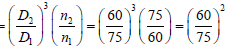
Two equal lengths of steel wires of the same diameter are made into two springs S1 and S2 of mean diameters 75 mm and 60 mm respectively. The stiffness ratio of S1 to S2 is - a)

- b)

- c)

- d)

Correct answer is option 'A'. Can you explain this answer?
Two equal lengths of steel wires of the same diameter are made into two springs S1 and S2 of mean diameters 75 mm and 60 mm respectively. The stiffness ratio of S1 to S2 is
a)
b)
c)
d)
|
|
Avinash Sharma answered |
But most of the students think answer will be (b). If your calculated answer is also (b) then read the question again and see “Two equal lengths of steel wires” is written that means number of turns are different.
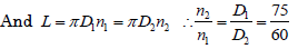
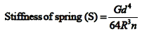 Where G and d issame
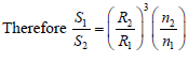

A rod of length L and diameter D is subjected to a tensile load P. Which of the following is sufficient to calculate the resulting change in diameter?- a)Young's modulus
- b)Shear modulus
- c)Poisson's ratio
- d)Both Young's modulus and shear modulus
Correct answer is option 'D'. Can you explain this answer?
A rod of length L and diameter D is subjected to a tensile load P. Which of the following is sufficient to calculate the resulting change in diameter?
a)
Young's modulus
b)
Shear modulus
c)
Poisson's ratio
d)
Both Young's modulus and shear modulus

|
Rahul Sen answered |
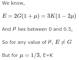
Both Poison’s ratio and Young’s Modulus are required to calculate the lateral strain in rod Now m,E and N are related by
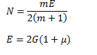
So E and G are required if

is given
If a piece of material neither expands nor contracts in volume when subjected to stress, then the Poisson‟s ratio must be- a)Zero
- b)0.25
- c)0.33
- d)0.5
Correct answer is 'D'. Can you explain this answer?
If a piece of material neither expands nor contracts in volume when subjected to stress, then the Poisson‟s ratio must be
a)
Zero
b)
0.25
c)
0.33
d)
0.5
|
|
Ishan Malik answered |
€v=0. (1-2¥)×(£x+£y+£z)/E =0. since body is constrained in all directions there will be equal stress in all directions. £x=£y=£z. 1-2¥=0. ¥=1/2= 0.5 ans.
Can you explain the answer of this question below:What is the phenomenon of progressive extension of the material i.e., strain increasing with the time at a constant load, called?- A:Plasticity
- B:Yielding
- C:Creeping
- D:Breaking
The answer is c.
What is the phenomenon of progressive extension of the material i.e., strain increasing with the time at a constant load, called?
A:
Plasticity
B:
Yielding
C:
Creeping
D:
Breaking

|
Varun Tankala answered |
The creeping is the phenomenon of deformation in materials which have been under load for several time. When the load is put on the material, initially it deforms but when the load is not removed, it causes a small amount of deformation which increases with time. so answer is C
A steel rod 10 mm in diameter and 1m long is heated from 20 °C to 120°C, E = 200 GPa and α = 12 × 10-6 per °C. If the rod is not free to expand, the thermal stress developed is:- a)120 MPa (tensile)
- b)240 MPa (tensile)
- c)120 MPa (compressive)
- d)240 MPa (compressive)
Correct answer is option 'D'. Can you explain this answer?
A steel rod 10 mm in diameter and 1m long is heated from 20 °C to 120°C, E = 200 GPa and α = 12 × 10-6 per °C. If the rod is not free to expand, the thermal stress developed is:
a)
120 MPa (tensile)
b)
240 MPa (tensile)
c)
120 MPa (compressive)
d)
240 MPa (compressive)

|
Lekshmi Kaur answered |

It will be compressive as elongation restricted.
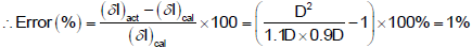
A bar of length L tapers uniformly from diameter 1.1 D at one end to 0.9 D at the other end. The elongation due to axial pull is computed using mean diameter D. What is the approximate error in computed elongation?- a)10%
- b)5%
- c)1%
- d)0.5%
Correct answer is option 'C'. Can you explain this answer?
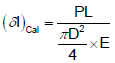
A bar of length L tapers uniformly from diameter 1.1 D at one end to 0.9 D at the other end. The elongation due to axial pull is computed using mean diameter D. What is the approximate error in computed elongation?
a)
10%
b)
5%
c)
1%
d)
0.5%
|
|
Deepak Choudhary answered |
Actual elongation of the bar 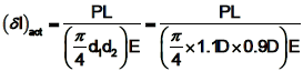
Calculated elongation of the bar
Two beams of equal cross-sectional area are subjected to equal bending moment. If one beam has square cross-section and the other has circular section, then- a)Both beams will be equally strong
- b)Circular section beam will be stronger
- c)Square section beam will be stronger
- d)The strength of the beam will depend on the nature of loading
Correct answer is option 'B'. Can you explain this answer?
Two beams of equal cross-sectional area are subjected to equal bending moment. If one beam has square cross-section and the other has circular section, then
a)
Both beams will be equally strong
b)
Circular section beam will be stronger
c)
Square section beam will be stronger
d)
The strength of the beam will depend on the nature of loading
|
|
Nitin Kapoor answered |
If D is diameter of circle and 'a' the side of square section,
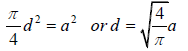
Z for circular section 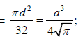 and Z for square section
and Z for square section In the case of an engineering material under unidirectional stress in the x -direction, the Poisson's ratio is equal to (symbols have the usual meanings)- a)

- b)

- c)

- d)

Correct answer is option 'A'. Can you explain this answer?
In the case of an engineering material under unidirectional stress in the x -direction, the Poisson's ratio is equal to (symbols have the usual meanings)
a)
b)
c)
d)
|
|
Yash Patel answered |
Since stress is in x direction, longitudinal strain will develop in x direction. and lateral strain will be in y direction. Poisson's ratio= lateral strain/ longitudinal strain.
Can you explain the answer of this question below:A block of steel is loaded by a tangential force on its top surface while the bottom surface is held rigidly. The deformation of the block is due to
- A:
Shear only
- B:
Bending only
- C:
Shear and bending
- D:
Torsion
The answer is a.
A block of steel is loaded by a tangential force on its top surface while the bottom surface is held rigidly. The deformation of the block is due to
Shear only
Bending only
Shear and bending
Torsion
|
|
Srestha Rane answered |
It is the definition of shear stress. The force is applied tangentially it is not a point load so you cannot compare it with a cantilever with a point load at its free end.
The safe stress for a hollow steel column which carries an axial load of 2100 kN is 125 MN/m2. if the external diameter of the column is 30cm, what will be the internal diameter?- a)25 cm
- b)26.19cm
- c)30.14 cm
- d)27.9 cm
Correct answer is option 'B'. Can you explain this answer?
The safe stress for a hollow steel column which carries an axial load of 2100 kN is 125 MN/m2. if the external diameter of the column is 30cm, what will be the internal diameter?
a)
25 cm
b)
26.19cm
c)
30.14 cm
d)
27.9 cm
|
|
Hrishikesh Chakraborty answered |
Area of the cross section of column = π/4 ( 0.302 – d2) m2
Area = load / stress .
So, π/4 ( 0.302 – d2) m2 = 21 / 125
d = 26.19cm.
Area = load / stress .
So, π/4 ( 0.302 – d2) m2 = 21 / 125
d = 26.19cm.
A test specimen is stressed slightly beyond the yield point and then unloaded. Its yield strength will- a)Decrease
- b)Increase
- c)Remains same
- d)Becomes equal to ultimate tensile strength
Correct answer is option 'B'. Can you explain this answer?
A test specimen is stressed slightly beyond the yield point and then unloaded. Its yield strength will
a)
Decrease
b)
Increase
c)
Remains same
d)
Becomes equal to ultimate tensile strength

|
Sagarika Patel answered |
Increased.because the specimen is strain hardened due to plastic deformation.
Can you explain the answer of this question below:A steel rod 10 mm in diameter and 1m long is heated from 20 °C to 120°C, E = 200 GPa and α = 12 × 10-6 per °C. If the rod is not free to expand, the thermal stress developed is:
- A:
120 MPa (tensile)
- B:
240 MPa (tensile)
- C:
120 MPa (compressive)
- D:
240 MPa (compressive)
The answer is d.
A steel rod 10 mm in diameter and 1m long is heated from 20 °C to 120°C, E = 200 GPa and α = 12 × 10-6 per °C. If the rod is not free to expand, the thermal stress developed is:
120 MPa (tensile)
240 MPa (tensile)
120 MPa (compressive)
240 MPa (compressive)
|
|
Avinash Sharma answered |
It will be compressive as elongation restricted.
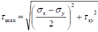
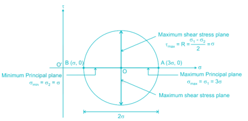
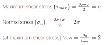
Two-dimensional state of stress at a point in a plane stressed element is represented by a Mohr circle of zero radius. Then both principal stresses- a)Are equal to zero
- b)Are equal to zero and shear stress is also equal to zero
- c)Are of equal magnitude but of opposite sign
- d)Are of equal magnitude and of same sign
Correct answer is option 'D'. Can you explain this answer?
Two-dimensional state of stress at a point in a plane stressed element is represented by a Mohr circle of zero radius. Then both principal stresses
a)
Are equal to zero
b)
Are equal to zero and shear stress is also equal to zero
c)
Are of equal magnitude but of opposite sign
d)
Are of equal magnitude and of same sign

|
Kaavya Sengupta answered |
Which one of the following features improves the fatigue strength of a metallic material?- a)Increasing the temperature
- b)Scratching the surface
- c)Overstressing
- d)Under stressing
Correct answer is 'D'. Can you explain this answer?
Which one of the following features improves the fatigue strength of a metallic material?
a)
Increasing the temperature
b)
Scratching the surface
c)
Overstressing
d)
Under stressing
|
|
Prateek Mukherjee answered |
Improving the Fatigue Strength of Metallic Material
Fatigue strength is the ability of a material to withstand repeated load cycles without failure. Here are some ways to improve the fatigue strength of a metallic material.
Under stressing
- Metallic materials have a certain level of stress that they can withstand without failing. Under stressing involves designing a component or structure such that the stress levels are kept below the material's endurance limit. This ensures that the material will not fail even after repeated load cycles, thereby improving its fatigue strength.
Other Factors
Apart from under stressing, the following factors can also improve the fatigue strength of metallic materials:
- Surface finish: A smooth surface finish can reduce the likelihood of stress concentration points, which can lead to fatigue failure. Therefore, improving the surface finish can improve the fatigue strength of a material.
- Material selection: Choosing a material with a high fatigue strength can improve the overall fatigue strength of a component or structure. For example, steel alloys such as AISI 4140 and AISI 4340 have high fatigue strengths and are commonly used in high-stress applications such as aircraft landing gears.
- Heat treatment: Heat treatment processes such as annealing, quenching, and tempering can improve the fatigue strength of metallic materials by altering their microstructure.
- Design optimization: Optimizing the design of a component or structure can reduce stress concentrations, improve load distribution, and reduce the likelihood of fatigue failure. This can include features such as fillets, chamfers, and radiuses at critical points.
Conclusion
In conclusion, under stressing is one of the ways to improve the fatigue strength of metallic materials. However, other factors such as surface finish, material selection, heat treatment, and design optimization can also play a crucial role in improving the fatigue strength of metallic materials.

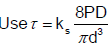
A close-coiled helical spring is made of 5 mm diameter wire coiled to 50 mm mean diameter. Maximum shear stress in the spring under the action of an axial force is 20 N/mm2. The maximum shear stress in a spring made of 3 mm diameter wire coiled to 30 mm mean diameter, under the action of the same force will be nearly - a)20 N/mm2
- b)33.3 N/mm2
- c)55.6 N/mm2
- d)92.6 N/mm2
Correct answer is option 'C'. Can you explain this answer?
A close-coiled helical spring is made of 5 mm diameter wire coiled to 50 mm mean diameter. Maximum shear stress in the spring under the action of an axial force is 20 N/mm2. The maximum shear stress in a spring made of 3 mm diameter wire coiled to 30 mm mean diameter, under the action of the same force will be nearly
a)
20 N/mm2
b)
33.3 N/mm2
c)
55.6 N/mm2
d)
92.6 N/mm2

|
Prashanth Rane answered |
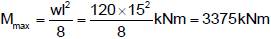
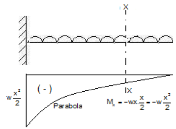
Solve the problems and choose correct answers A steel beam of breadth 120 mm and height 750 mm is loaded as shown in the figure. Assume Esteel= 200 GPa.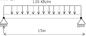 The beam is subjected to a maximum bending moment of
- a)3375 kNm
- b)4750 kNm
- c)6750 kNm
- d)8750 kNm
Correct answer is option 'A'. Can you explain this answer?
Solve the problems and choose correct answers A steel beam of breadth 120 mm and height 750 mm is loaded as shown in the figure. Assume Esteel= 200 GPa.
The beam is subjected to a maximum bending moment of
a)
3375 kNm
b)
4750 kNm
c)
6750 kNm
d)
8750 kNm

|
Cstoppers Instructors answered |
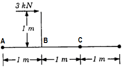
A simply supported beam carries a load 'P' through a bracket, as shown in Figure. The maximum bending moment in the beam is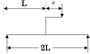
- a)PI/2
- b)PI/2 + aP/2
- c)PI/2 + aP
- d)PI/2 – aP
Correct answer is option 'C'. Can you explain this answer?
A simply supported beam carries a load 'P' through a bracket, as shown in Figure. The maximum bending moment in the beam is
a)
PI/2
b)
PI/2 + aP/2
c)
PI/2 + aP
d)
PI/2 – aP

|
Wasi Khan answered |
Answer is B the max reaction was at B and it was P/2+PA/2L *L gives b


The equivalent spring stiffness for the system shown in the given figure (S is the spring stiffness of each of the three springs) is: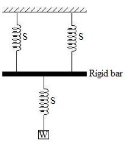
- a)S/2
- b)S/3
- c)2S/3
- d)S
Correct answer is option 'C'. Can you explain this answer?
The equivalent spring stiffness for the system shown in the given figure (S is the spring stiffness of each of the three springs) is:
a)
S/2
b)
S/3
c)
2S/3
d)
S

|
Raja Sharma answered |
First two springs are in parallel then Equivalent stiffness S +S = 2S,
this 2S is connected with Third spring S in series
so, 1/2S + 1/S = 1/ equivalent stiffness
* equi. stiffness= 2S/3.
this 2S is connected with Third spring S in series
so, 1/2S + 1/S = 1/ equivalent stiffness
* equi. stiffness= 2S/3.
A point, along the length of a beam subjected to loads, where bending moment changes its sign, is known as the point of- a)Inflexion
- b)Maximum stress
- c)Zero shear force
- d)Contra flexure
Correct answer is option 'D'. Can you explain this answer?
A point, along the length of a beam subjected to loads, where bending moment changes its sign, is known as the point of
a)
Inflexion
b)
Maximum stress
c)
Zero shear force
d)
Contra flexure
|
|
Anuj Chauhan answered |
Point of Contraflexure in a Beam
When a beam is subjected to transverse loads, it experiences bending moment and shear force. The bending moment is the algebraic sum of moments on either side of a section, while shear force is the algebraic sum of the forces on either side of the section. The distribution of bending moment and shear force along the beam depends on the type of loading, boundary conditions, and cross-sectional shape of the beam.
One of the important concepts in the analysis of beams is the point of contraflexure, which is defined as the point along the length of the beam where the bending moment changes its sign. At this point, the moment changes from positive (tending to cause sagging) to negative (tending to cause hogging), or vice versa. The term "contraflexure" means the opposite of flexure or bending, and indicates a change in the curvature of the beam.
The point of contraflexure can be identified by plotting the bending moment diagram for the beam, which shows the variation of bending moment with distance. The point of contraflexure is the point where the bending moment curve intersects the horizontal axis, i.e., the moment is zero. At this point, the curvature of the beam changes its direction, and the deflection of the beam also changes its sign.
Significance of Point of Contraflexure
The point of contraflexure has several implications for the behavior and design of beams, such as:
- It indicates the location where the maximum deflection occurs, as the curvature changes its sign.
- It affects the distribution of shear force along the beam, as the shear force is zero at the point of contraflexure.
- It can affect the design of supports and connections, as the change in curvature can cause stress concentrations and deformation.
- It is a critical factor in the analysis of beam stability, as the point of contraflexure can determine the mode of failure and collapse.
Therefore, the point of contraflexure is an important concept in the mechanics of materials and structural engineering, and should be carefully considered in the design and analysis of beams.
Euler's formula gives 5 to 10% error in crippling load as compared to experimental results in practice because:[IES-1998]- a)Effect of direct stress is neglected
- b)Pin joints are not free from friction
- c)The assumptions made in using the formula are not met in practice
- d)The material does not behave in an ideal elastic way in tension and compression
Correct answer is option 'C'. Can you explain this answer?
Euler's formula gives 5 to 10% error in crippling load as compared to experimental results in practice because:
[IES-1998]
a)
Effect of direct stress is neglected
b)
Pin joints are not free from friction
c)
The assumptions made in using the formula are not met in practice
d)
The material does not behave in an ideal elastic way in tension and compression
|
|
Prateek Mukherjee answered |
Explanation:
Euler's formula is a theoretical formula used to calculate the critical buckling load of a long, slender column under an axial compressive load. However, in practical situations, the formula may not give accurate results due to the following reasons:
1. Assumptions made in using the formula: Euler's formula assumes that the column is perfectly straight, homogeneous, isotropic, and has a constant cross-section throughout its length. However, in practice, these assumptions may not hold true, and the actual column may have imperfections, non-uniformities, and variations in cross-section, which can affect the critical buckling load.
2. Effect of direct stress is neglected: Euler's formula only considers the effect of compressive stress on the column, and neglects the effect of any other stresses, such as tensile or shear stresses, which may also contribute to the failure of the column.
3. Pin joints are not free from friction: Euler's formula assumes that the pin joints connecting the column to its supports are perfectly free to rotate without any friction. However, in practice, pin joints may have some friction, which can affect the critical buckling load.
4. Material does not behave in an ideal elastic way in tension and compression: Euler's formula assumes that the material of the column behaves in an ideal elastic way under both tension and compression. However, in practice, the material may not behave in this ideal way, and may exhibit plastic deformation, creep, or other non-elastic behaviors, which can affect the critical buckling load.
Conclusion:
Due to these factors, Euler's formula may give an error of 5 to 10% when compared to experimental results in practice. Therefore, it is important to consider these factors and use appropriate correction factors or more accurate analytical or numerical methods to calculate the critical buckling load of columns in practical situations.
A cantilever beam having 5 m length is so loaded that it develops a shearing force of 20T and a bending moment of 20 T-m at a section 2m from the free end. Maximum shearing force and maximum bending moment developed in the beam under this load are respectively 50 T and 125 T-m. The load on the beam is:- a)25 T concentrated load at free end
- b)20T concentrated load at free end
- c)5T concentrated load at free end and 2 T/m load over entire length
- d)10 T/m udl over entire length
Correct answer is option 'D'. Can you explain this answer?
A cantilever beam having 5 m length is so loaded that it develops a shearing force of 20T and a bending moment of 20 T-m at a section 2m from the free end. Maximum shearing force and maximum bending moment developed in the beam under this load are respectively 50 T and 125 T-m. The load on the beam is:
a)
25 T concentrated load at free end
b)
20T concentrated load at free end
c)
5T concentrated load at free end and 2 T/m load over entire length
d)
10 T/m udl over entire length
|
|
Rhea Reddy answered |

R
A
= 10 x 5 = 50T
M = 10 x 5 x (5/2) = 125 T.m
S.F diagram

For similar triangle
(50T/5)=(F/x) = (F/2)
\
F = 20T (at 2m from free end) and M ( at 2m from free end)
= (125 – 50 x 3 + 10 x 3 x(3/2)) T = 20 T-m
Assertion (A): Plastic deformation is a function of applied stress, temperature and strain rate.Reason (R): Plastic deformation is accompanied by change in both the internal and external state of the material.- a)Both A and R are individually true and R is the correct explanation of A
- b)Both A and R are individually true but R is NOT the correct explanation of A
- c)A is true but R is false
- d)A is false but R is true
Correct answer is option 'B'. Can you explain this answer?
Assertion (A): Plastic deformation is a function of applied stress, temperature and strain rate.
Reason (R): Plastic deformation is accompanied by change in both the internal and external state of the material.
a)
Both A and R are individually true and R is the correct explanation of A
b)
Both A and R are individually true but R is NOT the correct explanation of A
c)
A is true but R is false
d)
A is false but R is true
|
|
Anshul Sharma answered |
- Following the elastic deformation, material undergoes plastic deformation.
- Also characterized by relation between stress and strain at constant strain rate and temperature.
- Microscopically…it involves breaking atomic bonds, moving atoms, then restoration of bonds.
- Stress-Strain relation here is complex because of atomic plane movement, dislocation movement, and the obstacles they encounter.
- Crystalline solids deform by processes – slip and twinning in particular directions.
- Amorphous solids deform by viscous flow mechanism without any directionality.
- Equations relating stress and strain are called constitutive equations.
- A true stress-strain curve is called flow curve as it gives the stress required to cause the material to flow plastically to certain strain.
A thin cylindrical shell of mean diameter 750 mm and wall thickness 10 mm has its ends rigidly closed by flat steel plates. The shell is subjected to internal fluid pressure of 10 N/mm2 and an axial external pressure P1. If the longitudinal stress in the shell is to be zero, what should be the approximate value of P1? - a)8 N/mm2
- b)9 N/mm2
- c)10 N/mm2
- d)12 N/mm2
Correct answer is option 'C'. Can you explain this answer?
A thin cylindrical shell of mean diameter 750 mm and wall thickness 10 mm has its ends rigidly closed by flat steel plates. The shell is subjected to internal fluid pressure of 10 N/mm2 and an axial external pressure P1. If the longitudinal stress in the shell is to be zero, what should be the approximate value of P1?
a)
8 N/mm2
b)
9 N/mm2
c)
10 N/mm2
d)
12 N/mm2
|
|
Nitin Joshi answered |
Tensile longitudinal stress due to internal fluid pressure 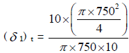 tensile. Compressive longitudinal stress due to external pressure
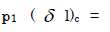
tensile. Compressive longitudinal stress due to external pressure 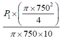
compressive. For zero longitudinal stress 
The temperature stress is a function of1. Coefficient of linear expansion 2. Temperature rise 3. Modulus of elasticity The correct answer is:- a)1 and 2 only
- b)1 and 3 only
- c)2 and 3 only
- d)1, 2 and 3
Correct answer is option 'D'. Can you explain this answer?
The temperature stress is a function of
1. Coefficient of linear expansion 2. Temperature rise 3. Modulus of elasticity The correct answer is:
a)
1 and 2 only
b)
1 and 3 only
c)
2 and 3 only
d)
1, 2 and 3
|
|
Sanya Agarwal answered |
Stress in the rod due to temperature rise 
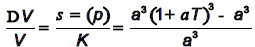
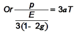
A cube having each side of length a, is constrained in all directions and is heated uniformly so that the temperature is raised to T°C. If α is the thermal coefficient of expansion of the cube material and E the modulus of elasticity, the stress developed in the cube is:- a)

- b)

- c)

- d)

Correct answer is option 'B'. Can you explain this answer?
A cube having each side of length a, is constrained in all directions and is heated uniformly so that the temperature is raised to T°C. If α is the thermal coefficient of expansion of the cube material and E the modulus of elasticity, the stress developed in the cube is:
a)
b)
c)
d)
|
|
Keerthana Bajaj answered |
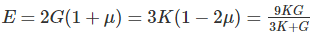
The independent elastic constants for a homogeneous and isotropic material are- a)E, G, K, v
- b)E, G, K
- c)E, G, v
- d)E, G
Correct answer is option 'D'. Can you explain this answer?
The independent elastic constants for a homogeneous and isotropic material are
a)
E, G, K, v
b)
E, G, K
c)
E, G, v
d)
E, G
|
|
Ameya Kaur answered |
The independent elastic constants for a homogeneous and isotropic material are E, G, and ν (Poisson's ratio).
Elastic Constants:
- Elastic constants are the physical properties of materials that describe their response to applied stress or strain.
- Elastic constants are used to calculate the deformation of materials under stress or strain.
- The three independent elastic constants for a homogeneous and isotropic material are Young's modulus (E), shear modulus (G), and Poisson's ratio (ν).
Young's Modulus (E):
- Young's modulus is a measure of the stiffness of a material.
- It quantifies the relationship between stress (force per unit area) and strain (deformation) in the linear region of the stress-strain curve.
- Young's modulus is defined as the ratio of stress to strain in the linear region of the curve.
- It has units of Pascals (Pa) or Newtons per square meter (N/m²).
Shear Modulus (G):
- Shear modulus is a measure of the resistance of a material to shear deformation.
- It quantifies the relationship between shear stress (force per unit area parallel to the surface) and shear strain (angular deformation) in the linear region of the stress-strain curve.
- Shear modulus is defined as the ratio of shear stress to shear strain in the linear region of the curve.
- It has units of Pascals (Pa) or Newtons per square meter (N/m²).
Poisson's Ratio (ν):
- Poisson's ratio is a measure of the lateral strain (transverse strain) that occurs when a material is subjected to axial strain (longitudinal strain).
- It quantifies the relationship between the transverse strain and the longitudinal strain.
- Poisson's ratio is defined as the negative ratio of transverse strain to longitudinal strain.
- It is dimensionless and typically ranges from 0 to 0.5 for most materials.
Conclusion:
- The independent elastic constants for a homogeneous and isotropic material are E, G, and ν.
- These elastic constants are used to calculate the deformation of materials under stress or strain.
- Young's modulus (E) is a measure of stiffness, shear modulus (G) is a measure of resistance to shear deformation, and Poisson's ratio (ν) is a measure of lateral strain.
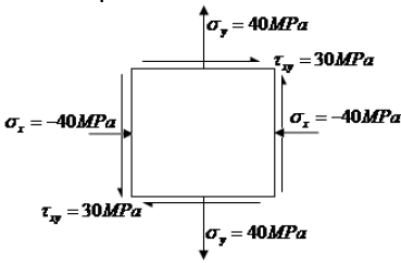
A piece of material is subjected, to two perpendicular tensile stresses of 70 MPa and 10 MPa. The magnitude of the resultant stress on a plane in which the maximum shear stress occurs is- a)70 MPa
- b)60 MPa
- c)50 MPa
- d)10 MPa
Correct answer is option 'C'. Can you explain this answer?
A piece of material is subjected, to two perpendicular tensile stresses of 70 MPa and 10 MPa. The magnitude of the resultant stress on a plane in which the maximum shear stress occurs is
a)
70 MPa
b)
60 MPa
c)
50 MPa
d)
10 MPa
|
|
Priyanka Tiwari answered |
Given data:
Perpendicular tensile stresses, σ₁ = 70 MPa and σ₂ = 10 MPa
To find:
Resultant stress on a plane in which maximum shear stress occurs.
Solution:
Let the plane on which maximum shear stress occurs be inclined at an angle of θ with the horizontal.
The normal stress on this plane can be given as:
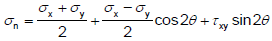
σₓ = (σ₁ + σ₂)/2 + (σ₁ - σ₂)/2 cos2θ
The shear stress on this plane can be given as:
τₓy = (σ₁ - σ₂)/2 sin2θ
To find the maximum shear stress, we need to differentiate the shear stress equation with respect to θ and equate it to zero.
dτₓy/dθ = (σ₁ - σ₂)/2 cos2θ = 0
cos2θ = 0
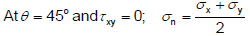
θ = 45°
Substituting θ = 45° in the above equations, we get:
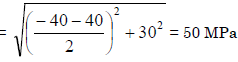
σₓ = (70 + 10)/2 + (70 - 10)/2 cos²45°
σₓ = 40 MPa
τₓy = (70 - 10)/2 sin2×45°
τₓy = 30 MPa
The magnitude of the resultant stress can be calculated using the following formula:
σR = √(σₓ² + 4τₓy²)
σR = √(40² + 4×30²)
σR = 50 MPa
Therefore, the correct option is (c) 50 MPa.
Perpendicular tensile stresses, σ₁ = 70 MPa and σ₂ = 10 MPa
To find:
Resultant stress on a plane in which maximum shear stress occurs.
Solution:
Let the plane on which maximum shear stress occurs be inclined at an angle of θ with the horizontal.
The normal stress on this plane can be given as:
σₓ = (σ₁ + σ₂)/2 + (σ₁ - σ₂)/2 cos2θ
The shear stress on this plane can be given as:
τₓy = (σ₁ - σ₂)/2 sin2θ
To find the maximum shear stress, we need to differentiate the shear stress equation with respect to θ and equate it to zero.
dτₓy/dθ = (σ₁ - σ₂)/2 cos2θ = 0
cos2θ = 0
θ = 45°
Substituting θ = 45° in the above equations, we get:
σₓ = (70 + 10)/2 + (70 - 10)/2 cos²45°
σₓ = 40 MPa
τₓy = (70 - 10)/2 sin2×45°
τₓy = 30 MPa
The magnitude of the resultant stress can be calculated using the following formula:
σR = √(σₓ² + 4τₓy²)
σR = √(40² + 4×30²)
σR = 50 MPa
Therefore, the correct option is (c) 50 MPa.


A thin walled spherical shell is subjected to an internal pressure. If the radius of the shell is increased by 1% and the thickness is reduced by 1%, with the internal pressure remaining the same, the percentage change in the circumferential (hoop) stress is - a)0
- b)1
- c)1.08
- d)2.02
Correct answer is 'D'. Can you explain this answer?
A thin walled spherical shell is subjected to an internal pressure. If the radius of the shell is increased by 1% and the thickness is reduced by 1%, with the internal pressure remaining the same, the percentage change in the circumferential (hoop) stress is
a)
0
b)
1
c)
1.08
d)
2.02

|
Shivam Sharma answered |
Hoop stress for a thin spherical shell (σh) = Pr/2t
By applying logarithm on both sides, we get
log(σh) = log(P/2) + log(r) − log(t)
Differentiating the above equation, f(t) = sin t and it is given that dr/r = 0.01 and dt/t = 0.01
Up on substituting we get, dσh/σh = 0.02
∴ Percentage increase will be 2%

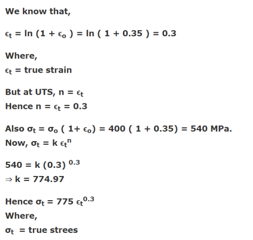
The ultimate tensile strength of a material is 400 MPa and the elongation up to maximum load is 35%. If the material obeys power law of hardening, then the true stress-true strain relation (stress in MPa) in the plastic deformation range is:- a)σ = 540ε0.30
- b)σ = 775ε0.30
- c)σ = 540ε0.35
- d)σ = 775ε0.35
Correct answer is option 'B'. Can you explain this answer?
The ultimate tensile strength of a material is 400 MPa and the elongation up to maximum load is 35%. If the material obeys power law of hardening, then the true stress-true strain relation (stress in MPa) in the plastic deformation range is:
a)
σ = 540ε0.30
b)
σ = 775ε0.30
c)
σ = 540ε0.35
d)
σ = 775ε0.35
|
|
Neha Choudhury answered |
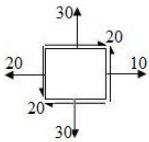
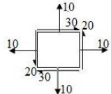
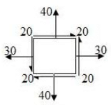
Biaxial stress system is correctly shown in- a)
- b)
- c)
- d)
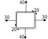
Correct answer is option 'C'. Can you explain this answer?
Biaxial stress system is correctly shown in
a)
b)
c)
d)

|
Bharath S answered |
Two equal and opposite force
In the case of bi-axial state of normal stresses, the normal stress on 45° plane is equal to- a)The sum of the normal stresses
- b)Difference of the normal stresses
- c)Half the sum of the normal stresses
- d)Half the difference of the normal stresses
Correct answer is option 'C'. Can you explain this answer?
In the case of bi-axial state of normal stresses, the normal stress on 45° plane is equal to
a)
The sum of the normal stresses
b)
Difference of the normal stresses
c)
Half the sum of the normal stresses
d)
Half the difference of the normal stresses
|
|
Siddharth Shah answered |
A static load is mounted at the centre of a shaft rotating at uniform angular velocity. This shaft will be designed for- a)The maximum compressive stress (static)
- b)The maximum tensile stress (static)
- c)The maximum bending moment (static)
- d)Fatigue loading
Correct answer is option 'D'. Can you explain this answer?
A static load is mounted at the centre of a shaft rotating at uniform angular velocity. This shaft will be designed for
a)
The maximum compressive stress (static)
b)
The maximum tensile stress (static)
c)
The maximum bending moment (static)
d)
Fatigue loading

|
Swara Dasgupta answered |
when shaft rotates at constant w, each fibre of the shaft will undergo tensile and compressive loads. Therefore, the shaft is under the action of cyclic load. Therefore the design should be for fatigue loading.
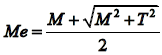
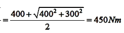
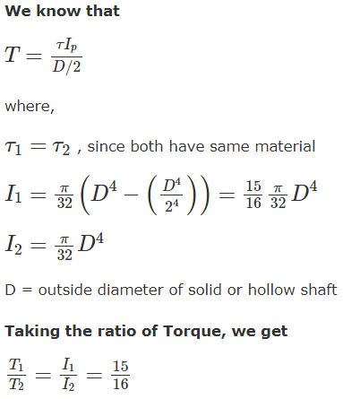
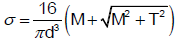
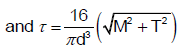
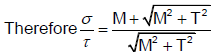
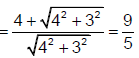
A circular solid shaft is subjected to a bending moment of 400 kNm and a twisting moment of 300 kNm. On the basis of the maximum principal stress theory, the direct stress is σ and according to the maximum shear stress theory, the shear stress is τ . The ratio σ/τ is:[IES-2000]- a)1/3
- b)3/9
- c)9/5
- d)11/6
Correct answer is option 'C'. Can you explain this answer?
A circular solid shaft is subjected to a bending moment of 400 kNm and a twisting moment of 300 kNm. On the basis of the maximum principal stress theory, the direct stress is σ and according to the maximum shear stress theory, the shear stress is τ . The ratio σ/τ is:
[IES-2000]
a)
1/3
b)
3/9
c)
9/5
d)
11/6
|
|
Yash Patel answered |
What are the materials which show direction dependent properties, called?- a)Homogeneous materials
- b)Viscoelastic materials
- c)Isotropic materials
- d)Anisotropic materials
Correct answer is option 'D'. Can you explain this answer?
What are the materials which show direction dependent properties, called?
a)
Homogeneous materials
b)
Viscoelastic materials
c)
Isotropic materials
d)
Anisotropic materials
|
|
Rajeev Sharma answered |
d. Anisotropic materials
Isotropic, Anisotropic, and Orthotrooic Materials
Materials can be classified as either isotropic or anisotropic.
Isotropic materials have the same material properties in all directions, and normal loads create only normal strains.
Anisotropic materials have different material properties in all directions at a point in the body.
Bulk materials, such as metals and polymers, are normally treated as isotropic materials, while composites are treated as anisotropic. However, even bulk materials such as metals can become anisotropic.
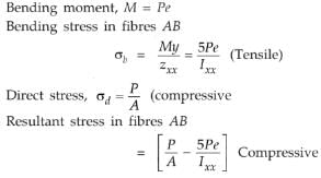
A shaft is subjected to simultaneous action of a torque T, bending moment M and an axial thrust F. Which one of the following statements is correct for this situation?
- a)Axial longitudinal fibre of the shaft is subjected to compressive stress only
- b)The opposite extreme end of the vertical diametral fibre is subjected to tensile/compressive stress only
- c)Every point on the surface of the shaft is subjected to maximum shear stress only
- d)One extreme end of the vertical diametral fibre is subjected to maximum compressive stress only
Correct answer is option 'A'. Can you explain this answer?
A shaft is subjected to simultaneous action of a torque T, bending moment M and an axial thrust F. Which one of the following statements is correct for this situation?
a)
Axial longitudinal fibre of the shaft is subjected to compressive stress only
b)
The opposite extreme end of the vertical diametral fibre is subjected to tensile/compressive stress only
c)
Every point on the surface of the shaft is subjected to maximum shear stress only
d)
One extreme end of the vertical diametral fibre is subjected to maximum compressive stress only

|
Anirban Khanna answered |
When a shaft is subjected to the simultaneous action of a torque T, bending moment M, and axial thrust F, only compressive stress is acted along the shaft's axial longitudinal fibre. Shear stress due to twisting and bending tension will be zero at the centroidal axis. As a result, only compressive stress will occur in the longitudinal direction.
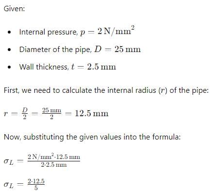
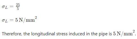
A thin walled water pipe carries water under a pressure of 2 N/mm2 and discharges water into a tank. Diameter of the pipe is 25 mm and thickness is 2·5 mm. What is the longitudinal stress induced in the pipe?
- a)0
- b)2 N/mm2
- c)5 N/mm2
- d)10 N/mm2
Correct answer is option 'C'. Can you explain this answer?
A thin walled water pipe carries water under a pressure of 2 N/mm2 and discharges water into a tank. Diameter of the pipe is 25 mm and thickness is 2·5 mm. What is the longitudinal stress induced in the pipe?
a)
0
b)
2 N/mm2
c)
5 N/mm2
d)
10 N/mm2
|
|
Isha Nambiar answered |
Chapter doubts & questions for Strength of Materials (SOM) - GATE Mechanical (ME) Mock Test Series 2026 2025 is part of Mechanical Engineering exam preparation. The chapters have been prepared according to the Mechanical Engineering exam syllabus. The Chapter doubts & questions, notes, tests & MCQs are made for Mechanical Engineering 2025 Exam. Find important definitions, questions, notes, meanings, examples, exercises, MCQs and online tests here.
Chapter doubts & questions of Strength of Materials (SOM) - GATE Mechanical (ME) Mock Test Series 2026 in English & Hindi are available as part of Mechanical Engineering exam.
Download more important topics, notes, lectures and mock test series for Mechanical Engineering Exam by signing up for free.
GATE Mechanical (ME) Mock Test Series 2026
30 docs|220 tests
|
|
© EduRev
|
Education Revolution
|


|


Signup to see your scores
go up
within 7 days!
within 7 days!
Takes less than 10 seconds to signup