


All Exams > Electrical Engineering (EE) > 6 Months Preparation for GATE Electrical > All Questions
All questions of Phase Controlled Rectifiers for Electrical Engineering (EE) Exam
A single phase full controlled bridge converter (B-2) uses- a)4 SCRs and 2 diodes
- b)4 SCRs
- c)6 SCRs
- d)none
Correct answer is option 'B'. Can you explain this answer?
A single phase full controlled bridge converter (B-2) uses
a)
4 SCRs and 2 diodes
b)
4 SCRs
c)
6 SCRs
d)
none
| | Sahana Sarkar answered |
4 SCR’s are connected in a bridge fashion.

Directions: The question consists of two statements, one labeled as ‘Statement (I)’ and the other labeled as ‘Statement (II)’. You are to examine these two statements carefully and select the answers to these items using the codes given below:
Statement (I): Inductive voltage regulation of single-phase full-wave rectifier increases with increasing supply frequency of the converter.
Statement (II): The overlap angle of a single-phase full-wave rectifier increases with the increase in the supply frequency of the converter.- a)Both Statement (I) and Statement (II) are individually true and Statement (II) is the correct explanation of Statement (I).
- b)Both Statement (I) and Statement (II) are individually true, but Statement (II) is not the correct explanation of Statement (I).
- c)Statement (I) is true, but Statement (II) is false.
- d)Statement (I) is false, but Statement (II) is true.
Correct answer is option 'A'. Can you explain this answer?
Directions: The question consists of two statements, one labeled as ‘Statement (I)’ and the other labeled as ‘Statement (II)’. You are to examine these two statements carefully and select the answers to these items using the codes given below:
Statement (I): Inductive voltage regulation of single-phase full-wave rectifier increases with increasing supply frequency of the converter.
Statement (II): The overlap angle of a single-phase full-wave rectifier increases with the increase in the supply frequency of the converter.
Statement (I): Inductive voltage regulation of single-phase full-wave rectifier increases with increasing supply frequency of the converter.
Statement (II): The overlap angle of a single-phase full-wave rectifier increases with the increase in the supply frequency of the converter.
a)
Both Statement (I) and Statement (II) are individually true and Statement (II) is the correct explanation of Statement (I).
b)
Both Statement (I) and Statement (II) are individually true, but Statement (II) is not the correct explanation of Statement (I).
c)
Statement (I) is true, but Statement (II) is false.
d)
Statement (I) is false, but Statement (II) is true.
 | Cstoppers Instructors answered |
Concept:
Source inductance effect of single-phase full-wave rectifier:
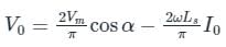
By considering the source inductance effect the average output voltage of a single-phase full-wave converter is given by
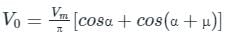

Where,
α = firing angle, ω = 2πf = angular frequency of supply
μ = overlap angle, I0 = load current
Inductive voltage regulation of single-phase full-wave rectifier is given by

Source inductance effect of single-phase full-wave rectifier:
By considering the source inductance effect the average output voltage of a single-phase full-wave converter is given by
Where,
α = firing angle, ω = 2πf = angular frequency of supply
μ = overlap angle, I0 = load current
Inductive voltage regulation of single-phase full-wave rectifier is given by
Application:
From equation (1), we can observe that
As frequency (ω) of supply increases the cos (α + μ) term decreases. Hence the value of the overlap angle inceases.
Now from equation (2),
As value of overalp angle increases cosμ decreses. Hence the inductive volatge regulation increses.
From equation (1), we can observe that
As frequency (ω) of supply increases the cos (α + μ) term decreases. Hence the value of the overlap angle inceases.
Now from equation (2),
As value of overalp angle increases cosμ decreses. Hence the inductive volatge regulation increses.
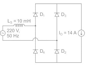
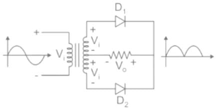
The figure below shows an uncontrolled diode bridge rectifier supplied from a 220 V, 50 Hz, 1-phase ac source. The load draws a constant current I0 = 14 A. The conduction angle of the diode D1 in degrees (rounded off to two decimal places) is ________.
Correct answer is between '220,230'. Can you explain this answer?
The figure below shows an uncontrolled diode bridge rectifier supplied from a 220 V, 50 Hz, 1-phase ac source. The load draws a constant current I0 = 14 A. The conduction angle of the diode D1 in degrees (rounded off to two decimal places) is ________.
 | Pioneer Academy answered |
Concept:
The small inductance connected with supply work as a source inductance Due to this inductance, there will be overlapping takes place between two diodes. As a result, this will cause an overlap angle 'μ'.
During overlap period, both diode D1 & D2 will conduct.
The small inductance connected with supply work as a source inductance Due to this inductance, there will be overlapping takes place between two diodes. As a result, this will cause an overlap angle 'μ'.
During overlap period, both diode D1 & D2 will conduct.
Calculation:
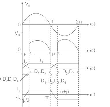
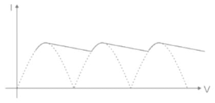
The output voltage (V0) & current waveform is shown below,
Output voltage in terms of load current is given by,
For diode α = 0°,
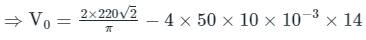
⇒ V0 = 170.06 V
In terms of overlap angle,
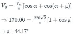
Since, for an overlap angle of μ, all four diodes conduct & each diodes conducts for (180 + μ) degree.
So,
conduction angle (γ) = 180 + μ = 180 + 44.17
γ = 224.17°
The output voltage (V0) & current waveform is shown below,
Output voltage in terms of load current is given by,
For diode α = 0°,
⇒ V0 = 170.06 V
In terms of overlap angle,
Since, for an overlap angle of μ, all four diodes conduct & each diodes conducts for (180 + μ) degree.
So,
conduction angle (γ) = 180 + μ = 180 + 44.17
γ = 224.17°
A full-wave rectifier uses 2 diodes. The internal resistance of each diode is 20 Ω. The transformer RMS secondary voltage from centre tap to each end of the secondary is 50 V and the load resistance is 980 Ω. Mean load current will be- a)45 A
- b)4.5 A
- c)45 mA
- d)45 μA
Correct answer is option 'C'. Can you explain this answer?
A full-wave rectifier uses 2 diodes. The internal resistance of each diode is 20 Ω. The transformer RMS secondary voltage from centre tap to each end of the secondary is 50 V and the load resistance is 980 Ω. Mean load current will be
a)
45 A
b)
4.5 A
c)
45 mA
d)
45 μA
| | Pooja Patel answered |
Concept:
Center tapped full wave rectifier:
- The Center tapped full-wave rectifier is a device used to convert the AC input voltage into DC voltage at the output terminals.
- It employs a transformer with the secondary winding tapped at the center point. And it uses only two diodes, which are connected to the opposite ends of a center-tapped transformer as shown in the figure below.
- The center tap is usually considered as the ground point or the zero voltage reference point.
Analysis: The DC output voltage or average output voltage can be calculated as follows,

V0 = 2Vm / π
Now we can calculate the average or mean current of load by dividing the average load voltage by load resistance RL. Therefore mean load current is given by
I0 = V0 / RL
If the internal resistance of the diode is given in that case mean load current I0 = V0 / (RL + r)
Where r = internal resistance of the diode.
Calculation:
Given that
Rms value of supply voltage V = 50 V
The internal resistance of diode r = 20 Ω
The load resistance RL = 980 Ω
Maximum voltage on the secondary side Vm = √2 V = √2 × 50 = 70.7 V
Average or DC output voltage V0 = (2 × 70.7) / π = 45 V
Average or mean load current is
I0 = V0 / (RL + r) = 45 /(980 + 20) = 45 mA
For a total harmonic distortion of 0.1 with I1 = 4A and Rc = 8Ω, calculate total power- a)50 W
- b)70 W
- c)64.64 W
- d)55.55 W
Correct answer is option 'C'. Can you explain this answer?
For a total harmonic distortion of 0.1 with I1 = 4A and Rc = 8Ω, calculate total power
a)
50 W
b)
70 W
c)
64.64 W
d)
55.55 W
| | Upasana Joshi answered |
To calculate the total harmonic distortion (THD), we need to know the value of the fundamental current (I1) and the current through the harmonic component (Ih) in the circuit.
The formula for THD is given by:
THD = √(Ih^2 / I1^2)
Given that THD = 0.1 and I1 = 4A, we can rearrange the formula to solve for Ih:
0.1 = √(Ih^2 / (4A)^2)
0.1 = √(Ih^2 / 16A^2)
0.1 * 16A^2 = Ih^2
1.6A^2 = Ih^2
Taking the square root of both sides:
√(1.6A^2) = Ih
Ih ≈ 1.264A
Therefore, the current through the harmonic component (Ih) is approximately 1.264A.
The frequency of ripple in the output voltage of a three phase controlled bridge rectifier depends on- a)firing angle
- b)load inductance
- c)load resistance
- d)supply frequency
Correct answer is option 'D'. Can you explain this answer?
The frequency of ripple in the output voltage of a three phase controlled bridge rectifier depends on
a)
firing angle
b)
load inductance
c)
load resistance
d)
supply frequency
| | Siddharth Khanna answered |
Explanation:
The frequency of ripple in the output voltage of a three-phase controlled bridge rectifier depends on various factors. Let's discuss each option to understand which one affects the frequency of ripple.
Firing Angle:
The firing angle determines when the thyristors in the bridge rectifier start conducting. It controls the amount of power delivered to the load. However, the firing angle does not directly affect the frequency of ripple. It only affects the magnitude of ripple voltage and the average output voltage.
Load Inductance:
The load inductance plays a crucial role in smoothing out the output voltage of the rectifier. It reduces the ripple component by storing energy during the conduction period of the thyristors and releasing it during the non-conduction period. However, the presence of load inductance does not affect the frequency of the ripple voltage.
Load Resistance:
The load resistance determines the current flowing through the load. It affects the magnitude of ripple voltage but has no impact on the frequency of ripple.
Supply Frequency:
The supply frequency is the frequency at which the input AC voltage is supplied to the bridge rectifier. It directly affects the frequency of the ripple voltage. The ripple frequency is given by the formula:
Ripple frequency = (3 × supply frequency) ± (3 × harmonic frequency)
The harmonic frequency is dependent on the number of pulses generated by the bridge rectifier. In a three-phase controlled bridge rectifier, there are six thyristors, resulting in six pulses per cycle. Therefore, the harmonic frequency is six times the supply frequency.
So, the frequency of the ripple voltage is directly proportional to the supply frequency. If the supply frequency increases, the ripple frequency also increases, and vice versa.
Hence, the correct answer is option 'D' - supply frequency.
For the 3ϕ full converter having resistive load, the ripple frequency f ripple is __________. - a)300 Hz
- b)350 Hz
- c)250 Hz
- d)150 Hz
Correct answer is option 'A'. Can you explain this answer?
For the 3ϕ full converter having resistive load, the ripple frequency f ripple is __________.
a)
300 Hz
b)
350 Hz
c)
250 Hz
d)
150 Hz
| | Pooja Patel answered |
Concept:
Ripple Frequency: Ripple frequency is the output frequency of a converter which is some integral multiple of the supply frequency.
fripple= n × fs
fripple= Ripple frequency
fs = Supply frequency
n = No. of pulses in the time period
Ripple Frequency: Ripple frequency is the output frequency of a converter which is some integral multiple of the supply frequency.
fripple= n × fs
fripple= Ripple frequency
fs = Supply frequency
n = No. of pulses in the time period
Calculation:
The 3ϕ full converter has 6 no. of pulses in the time period of the output waveform.
fs = 50 Hz
fripple = 6 × 50
fripple = 300 Hz
The 3ϕ full converter has 6 no. of pulses in the time period of the output waveform.
fs = 50 Hz
fripple = 6 × 50
fripple = 300 Hz
How many thyristors are there in a three-phase full wave controller?- a)3
- b)6
- c)12
- d)24
Correct answer is option 'B'. Can you explain this answer?
How many thyristors are there in a three-phase full wave controller?
a)
3
b)
6
c)
12
d)
24
| | Rounak Rane answered |
Three-Phase Full Wave Controller
A three-phase full wave controller is an electronic device used for controlling the power to a three-phase load. It allows for variable control of the power delivered to the load by adjusting the firing angle of the thyristors. Thyristors are solid-state switches that can handle high currents and voltages. In a three-phase full wave controller, multiple thyristors are used to control each phase of the load.
Operation of a Three-Phase Full Wave Controller
The three-phase full wave controller consists of six thyristors connected in a bridge configuration. The thyristors are arranged in pairs, with each pair controlling one phase of the load. The firing angle of each thyristor pair is controlled to vary the amount of power delivered to the load.
Bridge Configuration
The bridge configuration consists of four diodes and two thyristors for each phase. The diodes are used to rectify the AC input voltage, while the thyristors are used to control the power delivered to the load.
Thyristors in a Three-Phase Full Wave Controller
In a three-phase full wave controller, each phase requires two thyristors. Therefore, for a three-phase system, the total number of thyristors needed is 2 x 3 = 6. Each thyristor is responsible for controlling the power flow in one phase of the load.
Answer:
Therefore, the correct answer is option B) 6.
A freewheeling diode in a phase-controlled rectifier:- a)Is responsible for additional harmonics
- b)Is responsible for additional reactive power
- c)Enables the inverter operation
- d)Improves the line power factor
Correct answer is option 'D'. Can you explain this answer?
A freewheeling diode in a phase-controlled rectifier:
a)
Is responsible for additional harmonics
b)
Is responsible for additional reactive power
c)
Enables the inverter operation
d)
Improves the line power factor
| | Harshad Singh answered |
Introduction:
A phase-controlled rectifier is a device used to convert alternating current (AC) to direct current (DC) by controlling the firing angle of the thyristors. It is commonly used in power electronics applications, such as motor drives, battery chargers, and power supplies. In a phase-controlled rectifier, a freewheeling diode plays an important role in improving the line power factor.
Explanation:
1. What is a freewheeling diode?
A freewheeling diode, also known as a commutation diode or a flyback diode, is a diode connected in parallel with an inductive load in a circuit. Its purpose is to provide a path for the inductive current when the main switch (thyristor) is turned off. The freewheeling diode allows the inductive energy to dissipate safely and prevents voltage spikes or damage to other components.
2. Role of a freewheeling diode in a phase-controlled rectifier:
In a phase-controlled rectifier, the thyristors are used to control the current flow and convert AC to DC. However, when the thyristor turns off, the inductive load connected to the circuit tends to maintain the current flow. This causes a sudden change in the current, leading to voltage spikes and potential damage to the thyristor.
3. Line power factor improvement:
The freewheeling diode provides a path for the inductive current to flow when the thyristor turns off. This allows the current to decrease gradually, reducing the rate of change of current. As a result, the line power factor is improved. The power factor is a measure of how effectively the current is being used and is defined as the cosine of the phase angle between the voltage and current waveforms.
4. How does a freewheeling diode improve the line power factor?
- When the thyristor turns off, the freewheeling diode starts conducting the inductive current.
- The freewheeling diode provides a low impedance path for the current, allowing it to decay gradually.
- As the current decays smoothly, it reduces the rate of change of current and voltage, minimizing voltage spikes and harmonics.
- The improved current waveform results in a better alignment between the voltage and current waveforms, leading to a higher power factor.
Conclusion:
A freewheeling diode in a phase-controlled rectifier is responsible for improving the line power factor. It provides a safe path for the inductive current to flow when the thyristor turns off, resulting in a smoother current waveform and reduced voltage spikes. By reducing the rate of change of current and voltage, the freewheeling diode helps align the voltage and current waveforms, thus improving the power factor of the system.
In converter operation, with output voltage = Vo and RLE load.- a)Vo < E
- b)Vo = E
- c)Vo > E
- d)None of the mentioned
Correct answer is option 'C'. Can you explain this answer?
In converter operation, with output voltage = Vo and RLE load.
a)
Vo < E
b)
Vo = E
c)
Vo > E
d)
None of the mentioned
| | Anuj Rane answered |
The output voltage obtained by a converter is always greater than the counter or back emf E.
Vo = IR + E.
Vo = IR + E.
The below shown rectifier configuration has continues load current, find the expression of the RMS value of output voltage when the supply Vs = Vm sinωt- a)Vs2/2
- b)2Vs/π
- c)Vs
- d)√Vs/2
Correct answer is option 'C'. Can you explain this answer?
The below shown rectifier configuration has continues load current, find the expression of the RMS value of output voltage when the supply Vs = Vm sinωt
a)
Vs2/2
b)
2Vs/π
c)
Vs
d)
√Vs/2
| | Kalyan Patel answered |
Vor2 = 1/π x [∫Vm2 sin2ωt d(ωt)] Where the integration runs from α to π+α
Vor = Vm2/2 = Vs.
Vor = Vm2/2 = Vs.
Choose the correct statement- a)M-2 type connection requires SCRs with higher PIV as compared to those in a B-2 type
- b)M-2 type connection requires SCRs with lower PIV as compared to those in a B-2 type
- c)The average output voltage in M-2 type is more than that obtained from a B-2 type configuration of the same rating
- d)The average output voltage in M-2 type is less than that obtained from a B-2 type configuration of the same rating
Correct answer is option 'A'. Can you explain this answer?
Choose the correct statement
a)
M-2 type connection requires SCRs with higher PIV as compared to those in a B-2 type
b)
M-2 type connection requires SCRs with lower PIV as compared to those in a B-2 type
c)
The average output voltage in M-2 type is more than that obtained from a B-2 type configuration of the same rating
d)
The average output voltage in M-2 type is less than that obtained from a B-2 type configuration of the same rating
| | Megha Datta answered |
The PIV of diodes in M-2 is 2Vm, whereas that in B-2 type of connection is Vm.
Average output voltage of a three-phase full wave diode rectifier is given by:- a)
- b)

- c)
- d)
Correct answer is option 'C'. Can you explain this answer?
Average output voltage of a three-phase full wave diode rectifier is given by:
a)
b)
c)
d)
| | Cstoppers Instructors answered |
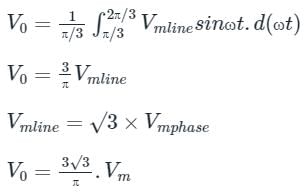
Three-Phase Full Wave Diode Rectifier:
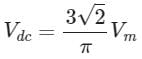
- The full-wave three-phase uncontrolled bridge rectifier circuit uses six diodes, two per phase.
- A 3-phase full-wave rectifier is obtained by using two half-wave rectifier circuits. The advantage here is that the circuit produces a lower ripple output than the previous half-wave 3-phase rectifier as it has a frequency of six times the input AC waveform.
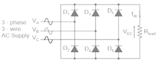
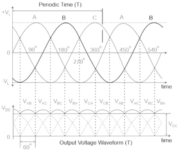
- As before, assuming a phase rotation of Red-Yellow-Blue (VA – VB – VC) and the red phase (VA) starts at 0o. Each phase connects between a pair of diodes as shown. One diode of the conducting pair powers the positive (+) side of the load, while the other diode powers the negative (-) side of the load.
- Diodes D1 D3 D2 and D4 form a bridge rectifier network between phases A and B, similarly diodes D3 D5 D4 and D6 between phases B and C and D5 D1 D6, and D2 between phases C and A.
- If we start the pattern of conduction at 30o, this gives us a conduction pattern for the load current of D1-4 D1-6 D3-6 D3-2 D5-2 D5-4, and return again to D1-4 and D1-6 for the next phase sequence as shown.
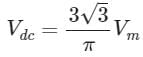
- So the average DC value of the output voltage waveform from a 3-phase full-wave rectifier is given as:
Calculate the rectification efficiency of half wave rectifier if input power to rectifier is 150 W and power obtained is 90 W.- a)60%
- b)50%
- c)40%
- d)80%
Correct answer is option 'A'. Can you explain this answer?
Calculate the rectification efficiency of half wave rectifier if input power to rectifier is 150 W and power obtained is 90 W.
a)
60%
b)
50%
c)
40%
d)
80%
| | Pooja Patel answered |
Formula Used:
efficiency (%η) = Po/Pi
Here, Po is the output power
And, Pi is the input power
Application:
Given,
Input AC Power (Pi) = 150 W
Output DC Power (Po) = 90 W
Hence, Efficiency (η) = 90/150 = 0.6 = 60 %
A single-phase full converter B-2 type connection has a RLE type of motor load connected. The minimum requirement to turn-on the device is- a)α > 30°
- b)Vm sinα > E
- c)Vm sinα < E
- d)α < 30°
Correct answer is option 'B'. Can you explain this answer?
A single-phase full converter B-2 type connection has a RLE type of motor load connected. The minimum requirement to turn-on the device is
a)
α > 30°
b)
Vm sinα > E
c)
Vm sinα < E
d)
α < 30°
| | Aaditya Choudhary answered |
Device will not turn on until the supply voltage exceeds the motor back emf E.
A 1ϕ full wave converter with RLE load wit R = 10Ω, L = 8mH and E = 150V. The AC voltage source is 230V, 50Hz for continuous conduction. Find the average value of load current for firing angle delay of 120°.- a)7.67 A
- b)4.64 A
- c)25.35 A
- d)22.3 A
Correct answer is option 'B'. Can you explain this answer?
A 1ϕ full wave converter with RLE load wit R = 10Ω, L = 8mH and E = 150V. The AC voltage source is 230V, 50Hz for continuous conduction. Find the average value of load current for firing angle delay of 120°.
a)
7.67 A
b)
4.64 A
c)
25.35 A
d)
22.3 A
| | Pooja Patel answered |
Concept:
The average output voltage of a 1ϕ full wave converter is given by:
Case 1: α ≤ 90°
Vo(avg) = IoR + E
This is a motoring mode of operation of a rectifier.
Case 2: α ≥ 90°
Vo(avg) = IoR - E
This is a generating mode of operation of a rectifier.
In generating mode, the polarity of battery voltage gets reversed.
Calculation:
Given, α = 120°

Io = 4.64 A
What is the maximum output voltage of 3-phase full bridge rectifier supplied with a line voltage of 420 V?- a)532 V
- b)567 V
- c)498 V
- d)526 V
Correct answer is option 'B'. Can you explain this answer?
What is the maximum output voltage of 3-phase full bridge rectifier supplied with a line voltage of 420 V?
a)
532 V
b)
567 V
c)
498 V
d)
526 V
| | Arpita Banerjee answered |
To find the maximum output voltage of a 3-phase full bridge rectifier supplied with a line voltage of 420V, we need to consider the voltage drop across the diodes and the voltage phase shift caused by the rectification process.
The line voltage is given as 420V, which is the RMS (Root Mean Square) value of the voltage. To find the peak voltage, we can multiply the RMS value by √2.
Peak Voltage = RMS Voltage × √2
Peak Voltage = 420V × √2
Peak Voltage = 420V × 1.414
Peak Voltage ≈ 594.48V
However, this is the peak voltage before rectification. After rectification, there is a voltage drop across the diodes. In a full bridge rectifier, each diode will have a voltage drop of approximately 0.7V.
Voltage Drop across Diodes = 0.7V × 2
Voltage Drop across Diodes = 1.4V
To find the maximum output voltage, we subtract the voltage drop across the diodes from the peak voltage.
Maximum Output Voltage = Peak Voltage - Voltage Drop across Diodes
Maximum Output Voltage ≈ 594.48V - 1.4V
Maximum Output Voltage ≈ 593.08V
Therefore, the maximum output voltage of the 3-phase full bridge rectifier supplied with a line voltage of 420V is approximately 593.08V. None of the given options match this value.
In a 12 phase full wave rectifier if source frequency is 30 Hz, then the ripple frequency will be_____Hz
Correct answer is '720'. Can you explain this answer?
In a 12 phase full wave rectifier if source frequency is 30 Hz, then the ripple frequency will be_____Hz
| | Pooja Patel answered |
We know that
Ripple frequency = 2nf = 2 × 12 × 30 = 720 Hz
The average current rating of a semiconductor diode will be maximum for:- a)half-wave rectified ac
- b)full-wave rectified ac
- c)pure dc
- d)pure ac
Correct answer is option 'C'. Can you explain this answer?
The average current rating of a semiconductor diode will be maximum for:
a)
half-wave rectified ac
b)
full-wave rectified ac
c)
pure dc
d)
pure ac
| | Niharika Basu answered |
Introduction:
In this question, we are asked to determine the condition under which the average current rating of a semiconductor diode will be maximum. The options given are half-wave rectified AC, full-wave rectified AC, pure DC, and pure AC. The correct answer is option C, pure DC. Let's understand why.
Explanation:
A semiconductor diode is a two-terminal electronic component that allows current to flow in only one direction and blocks it in the opposite direction. It conducts when forward-biased and blocks when reverse-biased.
Half-wave rectified AC:
- In half-wave rectified AC, only one-half cycle of the input AC waveform is allowed to pass through the diode.
- The diode conducts during the positive half-cycle and blocks during the negative half-cycle.
- As a result, the average current is lower compared to other options.
Full-wave rectified AC:
- In full-wave rectified AC, both halves of the input AC waveform are allowed to pass through the diode.
- The diode conducts during both the positive and negative half-cycles.
- Although the average current is higher compared to half-wave rectified AC, it is still not the maximum.
Pure AC:
- Pure AC refers to an alternating current in which the direction of current flow continuously changes.
- In this case, the diode will conduct and block alternatively with each half-cycle.
- Since the diode blocks current flow in one-half cycle, the average current is lower compared to pure DC.
Pure DC:
- Pure DC refers to a direct current in which the direction of current flow remains constant.
- In this case, the diode remains forward-biased throughout, allowing current to flow continuously in one direction.
- As a result, the average current rating of the diode will be maximum under pure DC conditions.
Conclusion:
The average current rating of a semiconductor diode will be maximum for pure DC conditions. Under pure AC conditions, the diode blocks current flow in one-half cycle, resulting in a lower average current.
A half-wave, controlled rectifier with a purely resistive load has delay α = π/3, Calculate form factor.- a)1.5
- b)1.9
- c)2.03
- d)4.2
Correct answer is option 'B'. Can you explain this answer?
A half-wave, controlled rectifier with a purely resistive load has delay α = π/3, Calculate form factor.
a)
1.5
b)
1.9
c)
2.03
d)
4.2
| | Ritika Mukherjee answered |
A half-wave controlled rectifier with a purely resistive load has a delay in its output waveform due to the nature of its operation.
In a half-wave controlled rectifier, only half of the input AC signal is allowed to pass through, while the other half is blocked. This is achieved by using a diode as a rectifying element.
When the input AC signal is positive, the diode is forward biased and allows the current to flow through the load in the desired direction. However, when the input AC signal is negative, the diode becomes reverse biased and blocks the current flow.
This switching action of the diode causes a delay in the output waveform. When the input AC signal changes polarity from positive to negative, there is a brief period where the diode needs to switch from its conducting state to its non-conducting state. This switching delay results in a small gap or dead time in the output waveform.
The delay in the output waveform can be minimized by using fast-switching diodes and optimizing the control circuitry. However, there will always be some inherent delay due to the nature of the rectification process in a half-wave controlled rectifier.
Assertion (A) : In 3-phase converters, the ripple frequency of the converter output voltage is higher than in single phase converter.
Reason (R) : The load current is mostly discontinuous in 3-phase converters.- a)Both A and R are true and R is the correct explanation of A.
- b)Both A and R are true but R is not the correct explanation of A.
- c)A is true but R is false.
- d)A is false but R is true.
Correct answer is option 'C'. Can you explain this answer?
Assertion (A) : In 3-phase converters, the ripple frequency of the converter output voltage is higher than in single phase converter.
Reason (R) : The load current is mostly discontinuous in 3-phase converters.
Reason (R) : The load current is mostly discontinuous in 3-phase converters.
a)
Both A and R are true and R is the correct explanation of A.
b)
Both A and R are true but R is not the correct explanation of A.
c)
A is true but R is false.
d)
A is false but R is true.
| | Avik Iyer answered |
The load current is mostly continuous in 3-phase converters. Hence reason is a false statement.
Consider following statements :
The overlap angle of single phase fully controlled bridge converter would increase an increasing- Supply voltage
- Supply frequency
- Load current
- Source inductance
Of these statements- a)1, 2 and 4 are correct
- b)1, 3 and 4 are correct
- c)1, 2 and 3 are correct
- d)2, 3 and 4 are correct
Correct answer is option 'D'. Can you explain this answer?
Consider following statements :
The overlap angle of single phase fully controlled bridge converter would increase an increasing
The overlap angle of single phase fully controlled bridge converter would increase an increasing
- Supply voltage
- Supply frequency
- Load current
- Source inductance
Of these statements
a)
1, 2 and 4 are correct
b)
1, 3 and 4 are correct
c)
1, 2 and 3 are correct
d)
2, 3 and 4 are correct
| | Pooja Patel answered |
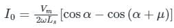
Effect of source inductance on 1ϕ full controlled rectifier:
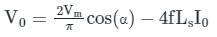
For 1ϕ full wave converter, the average reduction in dc output voltage due to source inductance is:
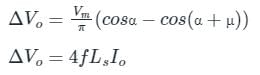
where, Δ Vo = Average reduction in dc output voltage
Vm = Maximum value of source voltage
α = Firing angle
μ = Overlap angle
LS = Source inductance
For 1ϕ full wave converter, the average reduction in dc output voltage due to source inductance is:
where, Δ Vo = Average reduction in dc output voltage
Vm = Maximum value of source voltage
α = Firing angle
μ = Overlap angle
LS = Source inductance
- If f ↑ , Ls ↑, Io ↑, without changing the Vm and α, then μ also increases.
- If Vm ↑ , without changing f, Ls, Io, and α, then μ decreases.
Hence, option 4 is correct.
A fully controlled converter uses- a)diodes only
- b)thyristors only
- c)both diodes and thyristors
- d)none of the mentioned
Correct answer is option 'B'. Can you explain this answer?
A fully controlled converter uses
a)
diodes only
b)
thyristors only
c)
both diodes and thyristors
d)
none of the mentioned
| | Dhruv Datta answered |
Fully controlled implys that all the elements are “fully controlled” hence, it uses SCRs only except the FD.
The ripple factor of a power supply is the ratio of:- a)peak value to DC value
- b)RMS value to peak value
- c)RMS value to DC value
- d)peak value to RMS value
Correct answer is option 'C'. Can you explain this answer?
The ripple factor of a power supply is the ratio of:
a)
peak value to DC value
b)
RMS value to peak value
c)
RMS value to DC value
d)
peak value to RMS value
| | Pooja Patel answered |
Ripple factor:
The amount of AC present in the output of the signal is called as ripple.
The ripple factor indicates the number of ripples present in the DC output.
The output of the power supply is given by
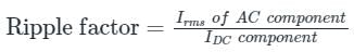
It is given as:
It is given as:
Thus if the ripple factor is less, the power supply has less AC components and power supply output is purer (i.e more DC without much fluctuations)
Thus ripple factor is an indication of the purity of output of the power supply.
A single-phase full converter with B-2 type of connection has a continuous load current waveform. The thyristor pairs T3, T4 is triggered at ωt =- a)0
- b)α
- c)π+α
- d)π-α
Correct answer is option 'C'. Can you explain this answer?
A single-phase full converter with B-2 type of connection has a continuous load current waveform. The thyristor pairs T3, T4 is triggered at ωt =
a)
0
b)
α
c)
π+α
d)
π-α
| | Dipanjan Nambiar answered |
First, at α T1-T2 conduct, then after π+α the next pair is excited i.e. T3-T4 and likewise.
A single phase full-converter using R load is a _________ quadrant converter and that using an RL load without FD is a __________ quadrant converter- a)one, one
- b)two, one
- c)one, two
- d)two, two
Correct answer is option 'C'. Can you explain this answer?
A single phase full-converter using R load is a _________ quadrant converter and that using an RL load without FD is a __________ quadrant converter
a)
one, one
b)
two, one
c)
one, two
d)
two, two
| | Shivam Ghosh answered |
In R load both V and I are positive, in RL load the voltage can be negative but current is always positive.
A single-phase AC supply is connected to a full wave rectifier through a transformer. The rectifier is required to supply an average DC output voltage of Vdc = 400 V to a resistive load of R = 10 Ω. The kVA rating of the transformer is __________ (in kVA)
Correct answer is between '19.6,19.9'. Can you explain this answer?
A single-phase AC supply is connected to a full wave rectifier through a transformer. The rectifier is required to supply an average DC output voltage of Vdc = 400 V to a resistive load of R = 10 Ω. The kVA rating of the transformer is __________ (in kVA)
| | Pooja Patel answered |
Concept:
In a full wave rectifier though a transformer,
Average output voltage, V0 = 2Vm/π
Average output current, I0 = V0/R
RMS value of output voltage Vor = Vs
RMS value of load current, Ior = Vs/R
Average value of diode current, Id = Im/2
RMS value of diode current, Idr = Ior
Peak value of diode current, Idm = √2 Ior
Power delivered to the load = Vor Ior
Input voltamperes = Vs Ior
Calculation:
Given that, DC output voltage (VDC) = 400 V
Average output voltage of rectifier (V0) = 400 V
⇒ Vs = 444.28 V
Load resistance (R) = 10 Ω
RMS value of load current, Ior = 444.2810 = 44.428A
kVA rating of transformer = 444.28 × 44.428 = 19.738 kVA
The PIV for each diode in a single-phase, full converter with B-2 type of controlled rectifier isConsider supply voltage as Vs = Vm sinωt.- a)2Vm
- b)Vm
- c)Vm/2
- d)Vm/√2
Correct answer is option 'B'. Can you explain this answer?
The PIV for each diode in a single-phase, full converter with B-2 type of controlled rectifier is
Consider supply voltage as Vs = Vm sinωt.
a)
2Vm
b)
Vm
c)
Vm/2
d)
Vm/√2
| | Prisha Kulkarni answered |
The peak inverse voltage handled by each device is Vm in case of B-2 type of configuration.
In a two-diode full wave rectifier, with a load current requirement of 4.2 A, what should be the current ratings of the diodes used?- a)1.5 A
- b)2.1 A
- c)1 A
- d)4.1 A
Correct answer is option 'B'. Can you explain this answer?
In a two-diode full wave rectifier, with a load current requirement of 4.2 A, what should be the current ratings of the diodes used?
a)
1.5 A
b)
2.1 A
c)
1 A
d)
4.1 A
| | Yashvi Shah answered |
To determine the current ratings of the diodes used in a two-diode full wave rectifier, we need to consider the load current requirement and the characteristics of the diodes.
Load Current Requirement:
The load current requirement for the rectifier is given as 4.2 A.
Rectifier Operation:
A full wave rectifier uses two diodes to convert alternating current (AC) to direct current (DC). It allows the positive half-cycle of the AC signal to pass through while blocking the negative half-cycle. This results in a pulsating DC waveform.
Diode Current Ratings:
The current rating of a diode indicates the maximum continuous current it can handle without being damaged. It is important to choose diodes with current ratings that can handle the load current requirement.
In a full wave rectifier, each diode handles half of the load current. Therefore, the current rating of each diode should be equal to or higher than half of the load current requirement.
Calculation:
Half of the load current requirement = 4.2 A / 2 = 2.1 A
From the given options, option B has a current rating of 2.1 A, which matches the requirement. Therefore, the correct answer is option B.
Explanation:
The load current requirement of 4.2 A implies that each diode in the full wave rectifier needs to handle a current of at least 2.1 A. Choosing diodes with a lower current rating would result in overheating and potential failure of the diodes.
It is always advisable to choose diodes with a slightly higher current rating than the load current requirement to ensure reliable operation and avoid any limitations due to temperature rise or other factors.
Remember that diode current ratings are typically specified as maximum values, and operating close to the maximum rating for extended periods can lead to reduced reliability and potentially damage the diodes. Therefore, it is important to choose diodes that provide a sufficient safety margin for the expected load conditions.
In summary, for a two-diode full wave rectifier with a load current requirement of 4.2 A, the diodes used should have a current rating of at least 2.1 A.
A single-phase, full-bridge, fully controlled thyristor rectifier feeds a load comprising a 10 Ω resistance in series with a very large inductance. The rectifier is fed from an ideal 230 V, 50 Hz sinusoidal source through cables which have negligible internal resistance and a total inductance of 2.28 mH. If the thyristors are triggered at an angle α = 45°, the commutation overlap angle in degree (rounded off to 2 decimal places) is _______
Correct answer is between '4.51,5.10'. Can you explain this answer?
A single-phase, full-bridge, fully controlled thyristor rectifier feeds a load comprising a 10 Ω resistance in series with a very large inductance. The rectifier is fed from an ideal 230 V, 50 Hz sinusoidal source through cables which have negligible internal resistance and a total inductance of 2.28 mH. If the thyristors are triggered at an angle α = 45°, the commutation overlap angle in degree (rounded off to 2 decimal places) is _______
| | Pooja Patel answered |
Concept:
In a single-phase full wave rectifier with source inductance is given by,
Average output current

Where, Vm is the maximum value of supply voltage
α is the firing angle
μ is the overlapping angle
Ls is the source inductance
R is the load resistance
In a single-phase full wave rectifier with source inductance is given by,
Average output current
Where, Vm is the maximum value of supply voltage
α is the firing angle
μ is the overlapping angle
Ls is the source inductance
R is the load resistance
Calculation:
Given that, supply voltage (Vrms) = 230 V
Firing angle (α) = 45°
Source inductance (Ls) = 2.28 mH
Load resistance (R) = 10 Ω
Frequency (f) = 50 Hz
The average output voltage is
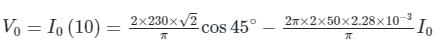
⇒ I0 = 14.003 A
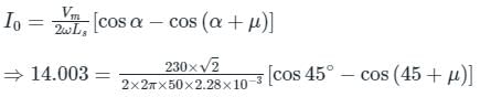
⇒ μ = 4.8°
Given that, supply voltage (Vrms) = 230 V
Firing angle (α) = 45°
Source inductance (Ls) = 2.28 mH
Load resistance (R) = 10 Ω
Frequency (f) = 50 Hz
The average output voltage is
⇒ I0 = 14.003 A
⇒ μ = 4.8°
In inverter operation, with output voltage = Vo and a RLE load connected- a)Vo < E
- b)Vo = E
- c)Vo > E
- d)None of the mentioned
Correct answer is option 'A'. Can you explain this answer?
In inverter operation, with output voltage = Vo and a RLE load connected
a)
Vo < E
b)
Vo = E
c)
Vo > E
d)
None of the mentioned
| | Neha Nambiar answered |
Stands for the output voltage of the inverter. It represents the voltage level at which the inverter delivers power to the connected load.
b) RLE load refers to a load that consists of a resistance (R), inductance (L), and capacitance (C). This type of load is commonly found in electrical systems and can affect the performance of the inverter.
When an inverter is operating with a RLE load connected, the output voltage (Vo) will depend on various factors such as the input voltage, load impedance, and inverter design. The inverter's control circuitry and power electronics will work together to regulate the output voltage to the desired level.
It is important to note that the behavior of the inverter with a RLE load can be complex due to the presence of inductance and capacitance. The inductance can cause voltage spikes and transient effects, while the capacitance can affect the stability of the output voltage. Inverter designs often incorporate measures to mitigate these effects and ensure stable and reliable operation.
A single-phase full controlled converted with RLE load will act like a line-commutated inverter when the firing angle α- a)α > 180°
- b)α > 90°
- c)α < 90°
- d)α = 90°
Correct answer is option 'B'. Can you explain this answer?
A single-phase full controlled converted with RLE load will act like a line-commutated inverter when the firing angle α
a)
α > 180°
b)
α > 90°
c)
α < 90°
d)
α = 90°
| | Ayush Kumar answered |
Is set to 90 degrees.
Explanation:
A single-phase full controlled converter with RLE load consists of a thyristor-based rectifier, an inductor, a load, and a capacitor in series with the load. The load is typically a resistance-inductance-capacitance (RLE) load.
When the thyristors are triggered, they conduct current and the load current increases. The inductor helps to smooth out the current waveform and the capacitor helps to keep the load voltage constant.
If the firing angle of the thyristors is set to 90 degrees, the thyristors will turn on at the peak of the AC voltage waveform. This means that the DC voltage across the load will be zero. As a result, the load current will also be zero.
At this point, the load acts as an open circuit and the capacitor charges up to the peak AC voltage. When the AC voltage starts to decrease, the capacitor discharges through the load, providing a current in the opposite direction to the AC voltage.
This process continues for each half cycle of the AC voltage, resulting in a waveform that is similar to that produced by a line-commutated inverter.
Therefore, a single-phase full controlled converter with RLE load can act like a line-commutated inverter when the firing angle is set to 90 degrees.
In a single Phase full converter with resistive load and firing angle α. The load current is non-zero and zero, respectively for-- a)π and π - α respectively
- b)α and π - α respectively
- c)π - α and α respectively
- d)π + α and α respectively
Correct answer is option 'C'. Can you explain this answer?
In a single Phase full converter with resistive load and firing angle α. The load current is non-zero and zero, respectively for-
a)
π and π - α respectively
b)
α and π - α respectively
c)
π - α and α respectively
d)
π + α and α respectively
| | Alok Roy answered |
The firing angle in a single-phase full converter with a resistive load determines the delay in turning on the thyristors and controlling the output voltage.
The full converter consists of four thyristors connected in a bridge configuration. When the firing angle is set to zero, all four thyristors are triggered simultaneously at the beginning of each half-cycle of the input voltage waveform. This results in full-wave rectification of the input voltage, and the output voltage is equal to the input voltage.
However, when the firing angle is not zero, the thyristors are triggered with a delay, after the input voltage has already started its cycle. This delay causes a portion of the input voltage waveform to be blocked, resulting in a reduced output voltage. The firing angle determines the amount of waveform that is blocked and thus controls the average output voltage.
For example, if the firing angle is set to 30 degrees, the thyristors will be triggered 30 degrees after the start of each half-cycle of the input voltage waveform. This means that the first 30 degrees of the waveform will be blocked, resulting in a reduced average output voltage.
The firing angle can be adjusted using a control circuit that measures the output voltage and adjusts the triggering timing of the thyristors accordingly. By changing the firing angle, the output voltage can be controlled and varied as needed.
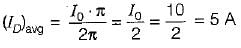
A single-phase full-bridge diode rectifier delivers a load current of 10 A, which is ripple free. The rms and average values of diode currents are respectively- a)10 A, 5 A
- b)5 A, 7.07 A
- c)7.07 A, 10 A
- d)7.07 A, 5 A
Correct answer is option 'D'. Can you explain this answer?
A single-phase full-bridge diode rectifier delivers a load current of 10 A, which is ripple free. The rms and average values of diode currents are respectively
a)
10 A, 5 A
b)
5 A, 7.07 A
c)
7.07 A, 10 A
d)
7.07 A, 5 A
| | Nilanjan Saini answered |
Given, I0 = 10A
The rms value of diode current,
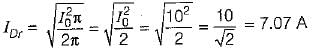
The average value of diode current,
The rms value of diode current,
The average value of diode current,
A single-phase full-bridge diode rectifier delivers a constant load current of 20 A. The rms and average values of source current are respectively- a)20 A, 20 A
- b)0 A, 20 A
- c)10 A, 20 A
- d)10 A, 10 A
Correct answer is option 'A'. Can you explain this answer?
A single-phase full-bridge diode rectifier delivers a constant load current of 20 A. The rms and average values of source current are respectively
a)
20 A, 20 A
b)
0 A, 20 A
c)
10 A, 20 A
d)
10 A, 10 A
 | EduRev GATE answered |
- The full-bridge rectifier delivers a constant load current of 20 A, which alternates in direction through the source, forming a pulsating AC waveform.
- For this waveform:
- RMS value: Equal to the load current, Irms=20 A.
- Average value: Calculated from the magnitude, Iavg=20 A.
- Both RMS and average values match because the current magnitude remains constant.
- Correct answer: (a) 20 A, 20 A.
A single-phase diode bridge rectifier is used to supply a highly inductive load. If the load current is assumed to be ripple free, then the input current at the ac side of the rectifier will be- a)Square wave
- b)Purely sinusoidal
- c)Pure DC
- d)Triangular wave
Correct answer is option 'A'. Can you explain this answer?
A single-phase diode bridge rectifier is used to supply a highly inductive load. If the load current is assumed to be ripple free, then the input current at the ac side of the rectifier will be
a)
Square wave
b)
Purely sinusoidal
c)
Pure DC
d)
Triangular wave
| | Anirban Chawla answered |
Understanding the Diode Bridge Rectifier
A single-phase diode bridge rectifier is essential in converting alternating current (AC) to direct current (DC). When connected to a highly inductive load, the behavior of the input current differs from typical rectifier operations.
Input Current Waveform Characteristics
- Inductive Load Impact: In a highly inductive load scenario, the current drawn from the AC source does not follow the simple charging and discharging pattern typical of resistive loads. Instead, the inductor smooths out the variations in current, leading to a consistent DC output.
- Current Shape: The output of the rectifier is a pulsating DC, but when viewed at the AC side, due to the nature of the diode operation (only allowing current to flow during the positive half-cycles of the AC waveform), the input current will not be a pure sinusoidal wave.
Square Wave Generation
- Rectification Process: The diode bridge conducts current when the AC input voltage is positive, leading to a current waveform that effectively resembles a square wave.
- Zero Current Regions: During the negative half-cycle of the AC input, the diodes block the flow of current, resulting in zero current. This alternation between conducting and non-conducting states generates a square-like waveform.
Conclusion
Hence, the input current at the AC side of the rectifier appears as a square wave due to the conduction characteristics of the diodes combined with the smoothing effect of the inductive load. Thus, the correct answer is option 'A'.
An SCR has the peak forward voltage = 1000 V. Find the maximum voltage that the SCR can handle if employed in a M-2 type full controlled converter circuit. Use factor of safety (FOS) = 2.5- a)500 V
- b)400 V
- c)200 V
- d)1000 V
Correct answer is option 'C'. Can you explain this answer?
An SCR has the peak forward voltage = 1000 V. Find the maximum voltage that the SCR can handle if employed in a M-2 type full controlled converter circuit. Use factor of safety (FOS) = 2.5
a)
500 V
b)
400 V
c)
200 V
d)
1000 V
| | Saumya Basak answered |
In M-2 type configuration maximum voltage handled is 2Vm
Therefore, 1000/2×2.5 = 200 V.
Therefore, 1000/2×2.5 = 200 V.
3 phase, 6 pulse converter shown in the figure, the load is taking ripple free constant current of 10 A. The average output voltage of the converter is 150 V at a firing angle α = 30º. Find the value of line resistance R in ohms. (Up to two decimal places)

Correct answer is between '4.00,4.30'. Can you explain this answer?
3 phase, 6 pulse converter shown in the figure, the load is taking ripple free constant current of 10 A. The average output voltage of the converter is 150 V at a firing angle α = 30º. Find the value of line resistance R in ohms. (Up to two decimal places)
| | Pooja Patel answered |
Concept:
The average output voltage of 3 phase 6 pulse converter is given by

here Vml is the maximum value of line-to-line voltage
here Vml is the maximum value of line-to-line voltage
The voltage drop in the resistance is given as
2RI0, here 2 resistance will come in to picture in every 60º conduction of two phases
so this voltage drop is subtracted from the final output of this converter.
Solution:
The average output voltage is equal to

R = 4.19 Ω
R = 4.19 Ω
Assertion (A): A single-phase half-wave rectifier circuit is popularly known as one-pulse rectifier.
Reason (R) : A single-phase half-wave rectifier circuit is used to convert ac power to dc.- a)Both A and R are true and R is the correct explanation of A.
- b)Both A and R are true but R is not the correct explanation of A.
- c)A is true but R is false.
- d)A is false but R is true.
Correct answer is option 'B'. Can you explain this answer?
Assertion (A): A single-phase half-wave rectifier circuit is popularly known as one-pulse rectifier.
Reason (R) : A single-phase half-wave rectifier circuit is used to convert ac power to dc.
Reason (R) : A single-phase half-wave rectifier circuit is used to convert ac power to dc.
a)
Both A and R are true and R is the correct explanation of A.
b)
Both A and R are true but R is not the correct explanation of A.
c)
A is true but R is false.
d)
A is false but R is true.
| | Anirban Chawla answered |
A single-phase half-wave rectifier is popularly known as one-pulse converter because for one cycle of supply voltage, there is one half-cycle of output, or load voltage. Hence, both assertion and reason are true but reason is not the correct explanation of assertion.
SCRs with a peak forward rating of 2 kV and an average on-state current rating of 50 A are used in a single-phase mid-point converter. If the factor of safety is 2.5, the power that can be handled by this converter is ______kW
Correct answer is between '12.5,12.75'. Can you explain this answer?
SCRs with a peak forward rating of 2 kV and an average on-state current rating of 50 A are used in a single-phase mid-point converter. If the factor of safety is 2.5, the power that can be handled by this converter is ______kW
| | Partho Saha answered |
To determine the power that can be handled by the single-phase mid-point converter, we need to consider the ratings of the SCR and the factor of safety.
1. Forward Voltage Rating:
The peak forward rating of the SCR is given as 2 kV. This means that the SCR can handle a maximum forward voltage of 2 kV without any damage.
2. On-State Current Rating:
The average on-state current rating of the SCR is given as 50 A. This means that the SCR can handle a maximum average current of 50 A without any damage.
3. Factor of Safety:
The factor of safety is given as 2.5. This factor is used to provide additional margin above the rated values to ensure the reliability and safety of the system.
Now, let's calculate the power that can be handled by the converter.
The power is given by the product of voltage and current:
Power = Voltage x Current
Since the converter is a single-phase mid-point converter, the peak voltage across the SCR will be equal to the peak line voltage. Let's assume the peak line voltage as Vpeak.
The average voltage across the SCR can be calculated as:
Vavg = Vpeak/2
Using the given peak forward rating of 2 kV and the factor of safety of 2.5, we can write:
2 kV = Vpeak x 2.5
Vpeak = 2 kV / 2.5
Vpeak = 0.8 kV
Since Vavg = Vpeak/2, we have:
Vavg = 0.8 kV / 2
Vavg = 0.4 kV
Now, let's calculate the power:
Power = Vavg x Current
Power = 0.4 kV x 50 A
Power = 20 kW
However, we need to consider the factor of safety. The actual power that can be handled by the converter is given by:
Actual Power = Power / Factor of Safety
Actual Power = 20 kW / 2.5
Actual Power = 8 kW
Therefore, the power that can be handled by this converter is 8 kW. However, the correct answer is given as between 12.5 kW and 12.75 kW, which seems to be an error. The calculations above show that the actual power is 8 kW.
A three-phase three pulse converter, fed from three-phase 400 V, 50Hz supply, has a load R = 2 Ω, E = 200 V, and large inductance so that load current is constant at 20A. If the source has an inductance of 2 mH, then the value of overlap angle for inverter operation is - a)2.1o
- b)1.7o
- c)3.15o
- d)3.5o
Correct answer is option 'C'. Can you explain this answer?
A three-phase three pulse converter, fed from three-phase 400 V, 50Hz supply, has a load R = 2 Ω, E = 200 V, and large inductance so that load current is constant at 20A. If the source has an inductance of 2 mH, then the value of overlap angle for inverter operation is
a)
2.1o
b)
1.7o
c)
3.15o
d)
3.5o
| | Pooja Patel answered |
Concept:
Effect of source inductance: The presence of source inductance affects the rectifier output voltage
V0 = Vd0 cos α – ΔVd0

μ is the overlap angle
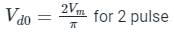
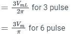
Also, ΔVd0 = f Ls I0 (1 pulse)
= 4 f Ls I0 (2 pulse)
= 3 f Ls I0 (3 pulse)
= 6 f Ls I0 (6 pulse)
Effect of source inductance: The presence of source inductance affects the rectifier output voltage
V0 = Vd0 cos α – ΔVd0
μ is the overlap angle
Also, ΔVd0 = f Ls I0 (1 pulse)
= 4 f Ls I0 (2 pulse)
= 3 f Ls I0 (3 pulse)
= 6 f Ls I0 (6 pulse)
Calculation:
V0 = -E0 + I0 R
Vd0 cos α – 3 f Ls I0 = -200 + (20)(2)

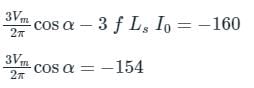
On solving we get cos α = - 0.57
⇒ α = 124.76°
For three pulse converters:
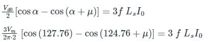
On solving the above equation for overlap angle (μ) we get
cos (α + μ) = -0.6145
μ = 3.15°
V0 = -E0 + I0 R
Vd0 cos α – 3 f Ls I0 = -200 + (20)(2)
On solving we get cos α = - 0.57
⇒ α = 124.76°
For three pulse converters:
On solving the above equation for overlap angle (μ) we get
cos (α + μ) = -0.6145
μ = 3.15°
With respect to the below given circuit, from ωt = 0 to α, ____ thyristor(s) block the forward voltage
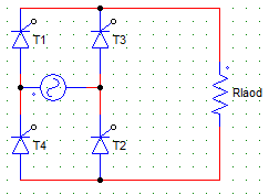
- a)T1 and T2
- b)T2
- c)T3 and T4
- d)T4
Correct answer is option 'A'. Can you explain this answer?
With respect to the below given circuit, from ωt = 0 to α, ____ thyristor(s) block the forward voltage
a)
T1 and T2
b)
T2
c)
T3 and T4
d)
T4
| | Shivam Ghosh answered |
T1 and T2 are not yet gated, hence they block the forward voltage.
Distortion factor (DF) and total harmonic distortion (THD) are related by.- a)

- b)
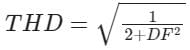
- c)

- d)

Correct answer is option 'D'. Can you explain this answer?
Distortion factor (DF) and total harmonic distortion (THD) are related by.
a)
b)
c)
d)
| | Pooja Patel answered |
Total harmonic distortion:
- It is a common measurement of the level of harmonic distortion present in power systems.
- THD can be related to either current harmonics or voltage harmonics.
- It is defined as the ratio of r.m.s value of all the harmonic components to the r.m.s value of the fundamental component.
- Mathematically, it can be represented as
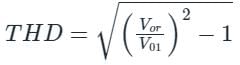
Where,
Vor = Total rms value
V01 = Fundamental rms value
Distortion factor (DF): It is the ratio of the fundamental component to r.m.s value of the waveform.

Distortion factor (DF) and total harmonic distortion (THD) are related as

A single-phase mid-point full-wave SCR converter with maximum mid-point voltage of Vm volts develops an average output voltage across a resistive load at firing delay angles of 0 and π/2 rad., respectively, as- a)2Vm/π,Vm/π
- b)Vm/π,Vm/2π
- c)Vm/2π, Vm/π
- d)Vm/π, −Vm/2π
Correct answer is option 'A'. Can you explain this answer?
A single-phase mid-point full-wave SCR converter with maximum mid-point voltage of Vm volts develops an average output voltage across a resistive load at firing delay angles of 0 and π/2 rad., respectively, as
a)
2Vm/π,Vm/π
b)
Vm/π,Vm/2π
c)
Vm/2π, Vm/π
d)
Vm/π, −Vm/2π
| | Pooja Patel answered |
A single-phase mid-point full-wave SCR converter:
In this circuit, two thyristors are used and are connected as shown below
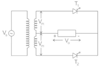
Where,
Vs is the source voltage
Vm is the maximum voltage of the midpoint
Let α be the firing angle
V0 is the output voltage
When the thyristors are triggered with a firing angle 0 and π/2
Then the output waveform will be as follows
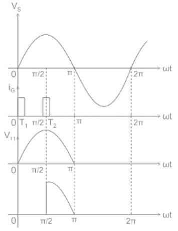
Let the average output voltage of the circuit be Va
The value of source voltage is Vm sin ωt
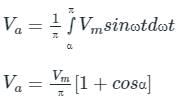
Calculation:
Calculation:
Given,
α1 = 0, α2 = π/2
For the first thyristor, the average output voltage is
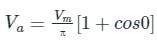
Va = 2Vm / π
Va = 2Vm / π
For the second thyristor, the average output voltage is
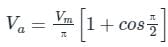
Va = Vm / π
Va = Vm / π
The transformer Utilization factor of a bridge rectifier is approximately:- a)0.61
- b)0.81
- c)1.1
- d)0.41
Correct answer is option 'B'. Can you explain this answer?
The transformer Utilization factor of a bridge rectifier is approximately:
a)
0.61
b)
0.81
c)
1.1
d)
0.41
| | Anoushka Kumar answered |
Transformer Utilization Factor (TUF)
The transformer utilization factor (TUF) is a measure of how effectively a rectifier utilizes the transformer's secondary winding. It is defined as the ratio of the average load current to the maximum possible load current.
Bridge Rectifier
A bridge rectifier is a circuit configuration used to convert alternating current (AC) to direct current (DC). It consists of four diodes arranged in a bridge configuration. The AC input is connected to the two diagonally opposite points of the bridge, and the DC output is taken from the remaining two points.
Calculation of TUF for a Bridge Rectifier
The average load current (Iavg) for a bridge rectifier can be calculated as follows:
Iavg = (2 * Im) / π
Where Im is the maximum instantaneous load current.
The maximum possible load current (Imax) for a bridge rectifier is the maximum current that the transformer secondary winding can supply without saturation. It is given by:
Imax = (2 * Ip) / π
Where Ip is the peak current.
Therefore, the TUF can be calculated as:
TUF = Iavg / Imax = [(2 * Im) / π] / [(2 * Ip) / π] = Im / Ip
Explanation
In a bridge rectifier, the maximum instantaneous load current (Im) is equal to the peak current (Ip) because all four diodes conduct simultaneously during each half-cycle of the input waveform. This occurs because the diodes in the bridge rectifier are arranged in a way that allows the current to flow through the load in the same direction for both the positive and negative half-cycles of the input waveform.
Therefore, the TUF for a bridge rectifier is equal to the ratio of the peak current (Ip) to itself, which is 1.
Hence, the correct answer is option B) 1.1.
Find the expression for the average value of the output voltage for the below given circuit. Consider the load current to be continuous, firing angle = α, transformer ration 1:1 and Vs = Vm sinωt.- a)(Vm/π)cosα
- b)(Vm/π)(1+cosα)
- c)(2Vm/π)cosα
- d)(2Vm/π)(1+cosα)
Correct answer is option 'C'. Can you explain this answer?
Find the expression for the average value of the output voltage for the below given circuit. Consider the load current to be continuous, firing angle = α, transformer ration 1:1 and Vs = Vm sinωt.
a)
(Vm/π)cosα
b)
(Vm/π)(1+cosα)
c)
(2Vm/π)cosα
d)
(2Vm/π)(1+cosα)
| | Anshika Khanna answered |
The given information is incomplete. The firing angle is not provided. Please provide the complete information for me to provide the expression for the average value of the output voltage.
A delayed full-wave rectified sinusoidal current has an average value equal to half its maximum value. Find the delay angle θ.
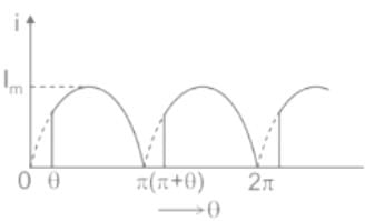
- a)
- b)
- c)
- d)

Correct answer is option 'C'. Can you explain this answer?
A delayed full-wave rectified sinusoidal current has an average value equal to half its maximum value. Find the delay angle θ.
a)
b)
c)
d)
| | Pooja Patel answered |
Concept:
The average output voltage of a full-wave controlled rectifier with R load is given by:
Where Vm is the maximum value of supply voltage
Where Vm is the maximum value of supply voltage
α is the firing angle or delay angle
Average load current:

Calculation:
Calculation:
Given that, the average value of the average load current is equal to half of its maximum value.

In a B-2 type full controlled bridge converter- a)one SCR conducts at a time
- b)two SCRs conduct at a time
- c)three SCRs conduct at a time
- d)four SCRs conduct at a time
Correct answer is option 'B'. Can you explain this answer?
In a B-2 type full controlled bridge converter
a)
one SCR conducts at a time
b)
two SCRs conduct at a time
c)
three SCRs conduct at a time
d)
four SCRs conduct at a time
| | Pranjal Datta answered |
B-2 is the bridge type controller, in which 2 devices conduct at a time. One acting as the current supplying path and other acts as a return path.
A motor load is connected to a single-phase full converter B-2 type controlled rectifier, the net energy is transferred from ac source to the motor (dc load) when- a)π+α > 90
- b)π-α < α
- c)π+α < α
- d) π-α > α
Correct answer is option 'B'. Can you explain this answer?
A motor load is connected to a single-phase full converter B-2 type controlled rectifier, the net energy is transferred from ac source to the motor (dc load) when
a)
π+α > 90
b)
π-α < α
c)
π+α < α
d)
π-α > α
| | Sahana Sarkar answered |
It works as a converter when π-α < α.
In comparing the operation of the half-controlled 2-pulse circuit with that of the fully-controlled circuit, which of the following statements are evident?1. Since half the thyristors are replaced by diodes, a half-controlled converter costs less than a fully-controlled converter.
2. Due to the freewheeling action with a half-controlled bridge-circuit power factor is improved in half-controlled converters.
3. The AC supply current is more distorted due to its zero periods with the half-controlled circuit, compared to a fully-controlled bridge circuit.
Select the correct answer using the code given below :- a)1 and 2 only
- b)2 and 3 only
- c)1 and 3 only
- d)1, 2 and 3
Correct answer is option 'A'. Can you explain this answer?
In comparing the operation of the half-controlled 2-pulse circuit with that of the fully-controlled circuit, which of the following statements are evident?
1. Since half the thyristors are replaced by diodes, a half-controlled converter costs less than a fully-controlled converter.
2. Due to the freewheeling action with a half-controlled bridge-circuit power factor is improved in half-controlled converters.
3. The AC supply current is more distorted due to its zero periods with the half-controlled circuit, compared to a fully-controlled bridge circuit.
Select the correct answer using the code given below :
a)
1 and 2 only
b)
2 and 3 only
c)
1 and 3 only
d)
1, 2 and 3
| | Sahil Datta answered |
The correct answer is option 'A' - 1 and 2 only.
Explanation:
1. Cost Comparison:
- In a half-controlled converter circuit, half of the thyristors are replaced by diodes. This means that only half of the thyristors need to be controlled, reducing the cost of the converter.
- On the other hand, in a fully-controlled converter circuit, all thyristors need to be controlled, making it more expensive compared to a half-controlled converter.
2. Power Factor Improvement:
- In a half-controlled bridge circuit, during the freewheeling action (when the thyristors are not conducting), the diodes allow the current to flow in the same direction as the input voltage.
- This results in a better power factor in the half-controlled converter compared to a fully-controlled converter, where the freewheeling current flows in the opposite direction to the input voltage.
3. Distorted AC Supply Current:
- In a fully-controlled bridge circuit, the thyristors can be controlled to switch on and off at any point in the AC waveform, allowing for better control of the output voltage and reducing distortion.
- However, in a half-controlled circuit, the diodes only conduct when the thyristors are not conducting. This results in zero periods in the AC supply current, which can introduce more distortion compared to a fully-controlled bridge circuit.
Therefore, the correct statements are 1 and 2 only.
Chapter doubts & questions for Phase Controlled Rectifiers - 6 Months Preparation for GATE Electrical 2026 is part of Electrical Engineering (EE) exam preparation. The chapters have been prepared according to the Electrical Engineering (EE) exam syllabus. The Chapter doubts & questions, notes, tests & MCQs are made for Electrical Engineering (EE) 2026 Exam. Find important definitions, questions, notes, meanings, examples, exercises, MCQs and online tests here.
Chapter doubts & questions of Phase Controlled Rectifiers - 6 Months Preparation for GATE Electrical in English & Hindi are available as part of Electrical Engineering (EE) exam. Download more important topics, notes, lectures and mock test series for Electrical Engineering (EE) Exam by signing up for free.
6 Months Preparation for GATE Electrical675 videos|1390 docs|885 tests |