


All Exams >
Mechanical Engineering >
Manufacturing Engineering >
All Questions
All questions of Machining & Machine Tool Operations for Mechanical Engineering Exam
My grandpa __________ (sleep) for three hours when I woke him up.Correct answer is 'had been sleeping'. Can you explain this answer?
My grandpa __________ (sleep) for three hours when I woke him up.
|
|
Saumya Dasgupta answered |
Explanation:
The correct answer to the given sentence is "had been sleeping" because it is in past perfect continuous tense. This tense is used to describe an action that was ongoing in the past before another action took place.
Here is a detailed explanation of the sentence:
- The sentence is in the past tense, as indicated by the word "woke" which is the past tense of "wake".
- The action of sleeping started before the moment of waking up and continued until that moment.
- The past perfect continuous tense is formed using the auxiliary verb "had" in the past perfect tense, the main verb "been" in the present participle form, and the main verb "sleep" in the base form with "-ing" added to the end.
- The sentence can be rephrased as "By the time I woke him up, he had been sleeping for three hours."
- The use of past perfect continuous tense emphasizes the duration of the action of sleeping that had been happening before the moment of waking up.
In summary, the correct answer "had been sleeping" indicates that the action of sleeping had started before the moment of waking up and had been ongoing for a duration of three hours until that moment.

Stroke of a shaping machine is 250 mm. It makes 30 double strokes per minute. Overall average speed of operation is- a)3.75 m/min
- b)5.0 m/min
- c)7.5 m/min
- d)15.0 m/min
Correct answer is option 'C'. Can you explain this answer?
Stroke of a shaping machine is 250 mm. It makes 30 double strokes per minute. Overall average speed of operation is
a)
3.75 m/min
b)
5.0 m/min
c)
7.5 m/min
d)
15.0 m/min

|
Shraddha Datta answered |
Given data:
Stroke of a shaping machine = 250 mm
Number of double strokes per minute = 30
To find: Overall average speed of operation
Formula used:
Overall average speed of operation = (length of stroke x number of double strokes per minute) / 1000
Calculation:
Substituting the given values in the formula, we get
Overall average speed of operation = (250 x 30) / 1000
= 7.5 m/min
Therefore, the correct answer is option C, i.e., 7.5 m/min.
Explanation:
The overall average speed of operation of a shaping machine is the distance traveled by the tool in one minute. As the machine makes 30 double strokes per minute, the tool travels a distance of 250 mm x 30 = 7500 mm or 7.5 m in one minute. Hence, the overall average speed of operation is 7.5 m/min.
Using the Taylor equation for tool life and letting n = 0.5 and C= 400, calculate the percentage increase in tool life when the cutting speed is reduced by 50%.- a)100%
- b)No change
- c)400%
- d)300%
Correct answer is option 'D'. Can you explain this answer?
Using the Taylor equation for tool life and letting n = 0.5 and C= 400, calculate the percentage increase in tool life when the cutting speed is reduced by 50%.
a)
100%
b)
No change
c)
400%
d)
300%
|
|
Vaibhav Khanna answered |
Taylor Equation for Tool Life:
The Taylor equation is used to determine the relationship between cutting speed and tool life. The equation is as follows:
VT^n = C
where,
V = cutting speed
T = tool life
n, C = constants
Calculating the Percentage Increase in Tool Life:
Given, n = 0.5 and C = 400
Let's assume the initial cutting speed is V1 and the corresponding tool life is T1. When the cutting speed is reduced by 50%, the new cutting speed becomes V2 = V1/2.
Using the Taylor equation, we can find the new tool life T2.
T1 = C/V1^n
T2 = C/V2^n
= C/(V1/2)^n
= C/(2^n * V1^n)
= (1/2^n) * (C/V1^n)
= (1/2^(0.5)) * T1
= 0.707 * T1
Therefore, the new tool life T2 is 0.707 times the initial tool life T1.
The percentage increase in tool life is given by:
((T2 - T1)/T1) * 100
= ((0.707T1 - T1)/T1) * 100
= -29.3%
However, we need to calculate the percentage increase in tool life when the cutting speed is reduced by 50%. This can be found as follows:
Percentage increase in tool life = |((T2 - T1)/T1) * 100|
= |((-0.293) * 100)|
= 29.3%
Therefore, the percentage increase in tool life when the cutting speed is reduced by 50% is 29.3%. This is option 'D'.
When machining a hard and brittle metal like cast iron, the type of chips produced is- a)continuous chips
- b)discontinuous chips
- c)fine chips
- d)continuous chips with built-up edge
Correct answer is option 'B'. Can you explain this answer?
When machining a hard and brittle metal like cast iron, the type of chips produced is
a)
continuous chips
b)
discontinuous chips
c)
fine chips
d)
continuous chips with built-up edge
|
|
Avinash Sharma answered |
Discontinuous chips are formed when machining brittle material at iow speed.
The portion of tool on which cutting edge is formed is known as- a)Shank
- b)Flank
- c)Face
- d)Nose
Correct answer is option 'A'. Can you explain this answer?
The portion of tool on which cutting edge is formed is known as
a)
Shank
b)
Flank
c)
Face
d)
Nose
|
|
Akshat Mehta answered |
Shank is called man body of cutting tool in which cutting edge is formed.

Which among the following is slowest speed operation in lathe?- a)Turning
- b)Thread cutting
- c)Taper turning
- d)Knurling
Correct answer is option 'A'. Can you explain this answer?
Which among the following is slowest speed operation in lathe?
a)
Turning
b)
Thread cutting
c)
Taper turning
d)
Knurling
|
|
Samarth Chaudhary answered |
The dummy activities are used to complete the iogical sequence, but do not consume any time or resources. A dummy activity is thus a connecting link for control purpose or for maintaining uniqueness of activity.
Tool signature is- a)a numerical method of identification of tool
- b)the plan of tool
- c)the procedure adopted for describing various tool angles
- d)used to describe the material of too
Correct answer is option 'C'. Can you explain this answer?
Tool signature is
a)
a numerical method of identification of tool
b)
the plan of tool
c)
the procedure adopted for describing various tool angles
d)
used to describe the material of too
|
|
Tanishq Rane answered |
The correct answer is option 'C', which states that tool signature is the procedure adopted for describing various tool angles. In the field of mechanical engineering, tool signature plays an important role in understanding and identifying the characteristics of a cutting tool. It consists of a set of numbers and symbols that provide information about the angles and dimensions of the tool.
The tool signature is used to describe the various angles associated with a cutting tool. These angles include:
1. Rake angle: It is the angle between the rake face of the tool and the normal to the machined surface. It determines the direction of chip flow and affects the cutting forces and tool life.
2. Relief angle: It is the angle between the flank of the tool and a line perpendicular to the machined surface. It provides clearance for the tool, reducing friction and minimizing the chance of built-up edge formation.
3. Side cutting edge angle: It is the angle between the side cutting edge of the tool and the machined surface. It determines the direction of cutting forces and affects the chip thickness and surface finish.
4. End cutting edge angle: It is the angle between the end cutting edge of the tool and the machined surface. It affects the cutting forces and surface finish.
5. Nose radius: It is the radius of curvature at the tip of the tool. It reduces the stress concentration and improves tool life.
The tool signature also includes information about the dimensions of the tool, such as the tool height, tool width, and nose radius. These dimensions are important for selecting the appropriate tool for a specific machining operation.
By using the tool signature, engineers and machinists can easily identify and select the right tool for a particular machining operation. It helps in optimizing cutting conditions, reducing tool wear, and improving productivity. Moreover, the tool signature is also useful in tool regrinding or replacement, as it provides a reference for restoring the original tool angles.
In conclusion, the tool signature is a procedure adopted for describing various tool angles. It is an essential tool in the field of mechanical engineering, providing valuable information for tool selection, optimization of cutting conditions, and tool maintenance.
Climb milling is chosen while machining because- a)the chip thickness increases gradually
- b)it enables the cutter to dig in and start the cut
- c)the specific power consumption is reduced
- d)better surface finish can be obtained
Correct answer is option 'C'. Can you explain this answer?
Climb milling is chosen while machining because
a)
the chip thickness increases gradually
b)
it enables the cutter to dig in and start the cut
c)
the specific power consumption is reduced
d)
better surface finish can be obtained
|
|
Kiran Basu answered |
Followings are the advantages of down or climb milling:
- cuttter tends to push the workpiece against the milling table in the downward direction thereby increasing the stability.
- the cutter has increased tool life as compared to up milling because of higher values of rake angle.
- specific power consumption is low.
- cuttter tends to push the workpiece against the milling table in the downward direction thereby increasing the stability.
- the cutter has increased tool life as compared to up milling because of higher values of rake angle.
- specific power consumption is low.
The regulating wheel of a centreless grinder is rotating at a surface speed of 127 mm/s and is inclined at an angle of 5°, Calculate the feed rate of material past the grinding wheel. [sin5° = 0.087, cos5° = 0.996]- a)5.2 mm/s
- b)8 mm/s
- c)11 mm/s
- d)14.2 mm/s
Correct answer is option 'C'. Can you explain this answer?
The regulating wheel of a centreless grinder is rotating at a surface speed of 127 mm/s and is inclined at an angle of 5°, Calculate the feed rate of material past the grinding wheel. [sin5° = 0.087, cos5° = 0.996]
a)
5.2 mm/s
b)
8 mm/s
c)
11 mm/s
d)
14.2 mm/s
|
|
Aniket Saini answered |
Degrees. The diameter of the regulating wheel is 254 mm.
To find the rotational speed of the regulating wheel, we can use the formula:
Rotational speed = Surface speed / Circumference
The circumference of the regulating wheel can be calculated using the formula:
Circumference = π * diameter
Circumference = 3.14 * 254 mm
Circumference = 798.36 mm
Now, we can calculate the rotational speed:
Rotational speed = 127 mm/s / 798.36 mm
Rotational speed ≈ 0.159 radians/s
Therefore, the rotational speed of the regulating wheel is approximately 0.159 radians/s.
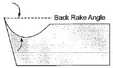
Trepanning operation is performed for- a)finishing a drilled hole
- b)trueing a hole for alignment
- c)producing large hole
- d)sizing a small hole
Correct answer is option 'C'. Can you explain this answer?
Trepanning operation is performed for
a)
finishing a drilled hole
b)
trueing a hole for alignment
c)
producing large hole
d)
sizing a small hole
|
|
Kajal Tiwari answered |
Trepanning is used to produce large size hole by removing a disk-shaped piece (core) usually from a flat plate. A hole is produced without reducing all the material removed to chip as is the case in drilling.
Nose radius is expressed in- a)Degree
- b)Radian
- c)mm
- d)Steradian
Correct answer is option 'C'. Can you explain this answer?
Nose radius is expressed in
a)
Degree
b)
Radian
c)
mm
d)
Steradian
|
|
Sparsh Chakraborty answered |
Nose radius is expressed in mm.
In which of the following milling operation cutter is rotated in the same direction of travel of work piece- a)Up milling
- b)Down milling
- c)Face milling
- d)End millingin
Correct answer is option 'B'. Can you explain this answer?
In which of the following milling operation cutter is rotated in the same direction of travel of work piece
a)
Up milling
b)
Down milling
c)
Face milling
d)
End millingin

|
Arjun Unni answered |
Down Milling:
Down milling is the milling operation in which the cutter rotates in the same direction as the travel of the workpiece. This type of milling is also known as climb milling. Let's understand why down milling is carried out in this manner.
Advantages of Down Milling:
- In down milling, the cutting forces tend to push the workpiece towards the table, resulting in a better surface finish.
- It reduces the risk of workpiece lifting off the table, ensuring better stability during the machining process.
- Down milling also helps in reducing tool wear and prolonging tool life.
- It is suitable for cutting materials that are prone to work hardening.
Comparison with Up Milling:
In up milling, the cutter rotates in the opposite direction to the travel of the workpiece. This type of milling is also known as conventional milling. Up milling has the following disadvantages compared to down milling:
- Up milling tends to create a rougher surface finish due to the cutting forces pulling the workpiece away from the table.
- It can cause workpiece chatter and vibration, leading to poor machining accuracy.
- Up milling is more likely to cause tool chipping and premature tool wear.
Conclusion:
In conclusion, down milling is preferred over up milling in most cases due to its advantages in terms of surface finish, stability, and tool life. It is important to consider the specific requirements of the machining operation and choose the appropriate milling technique accordingly.
In centre-less grinding, the work piece centre be- a)above the line joining the two wheel centres
- b)below the line joining the two wheel centres
- c)on the line joining the two wheel centres
- d)at the intersection of the line joining the wheel centre with workpiece plane
Correct answer is option 'A'. Can you explain this answer?
In centre-less grinding, the work piece centre be
a)
above the line joining the two wheel centres
b)
below the line joining the two wheel centres
c)
on the line joining the two wheel centres
d)
at the intersection of the line joining the wheel centre with workpiece plane
|
|
Dipika Kulkarni answered |
Centre-less grinding is used for grinding cylindrical workpieces without actual fixing the workpiece.
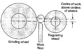
From the figure, the workpiece centre is above the centre of grinding and regulating wheel.
From the figure, the workpiece centre is above the centre of grinding and regulating wheel.
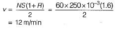
The ratio of time of return stroke to time of forward stroke of a shaping machine is 0.6. The stroke is 25C mm and it makes double strokes per minute. What is the overall average speed of operation?- a)3.75 m/min
- b)5.0 m/min
- c)7.5 m/min
- d)12 m/min
Correct answer is option 'D'. Can you explain this answer?
The ratio of time of return stroke to time of forward stroke of a shaping machine is 0.6. The stroke is 25C mm and it makes double strokes per minute. What is the overall average speed of operation?
a)
3.75 m/min
b)
5.0 m/min
c)
7.5 m/min
d)
12 m/min
|
|
Neha Mukherjee answered |
Consider the following statements:
Flutes are made in the drill:
1. To curl the chip lightly for easier removal
2. To allow the coolant and lubricant to get down to the cutting edge
3. To form the channels through which chips can escape from the hole
Which of these statements are correct?
- a)1,2 and 3
- b)1 and 2 only
- c)1 and 3 only
- d)2 and 3 only
Correct answer is option 'A'. Can you explain this answer?
Consider the following statements:
Flutes are made in the drill:
1. To curl the chip lightly for easier removal
2. To allow the coolant and lubricant to get down to the cutting edge
3. To form the channels through which chips can escape from the hole
Flutes are made in the drill:
1. To curl the chip lightly for easier removal
2. To allow the coolant and lubricant to get down to the cutting edge
3. To form the channels through which chips can escape from the hole
Which of these statements are correct?
a)
1,2 and 3
b)
1 and 2 only
c)
1 and 3 only
d)
2 and 3 only
|
|
Srestha Datta answered |
Purpose of flutes:
- help from the cutting edge of the drill point
- curl the chip lightly for easier removal
- form the channels through which chips can escape from the hole
- allow the coolant and lubricant to get down to the cutting edge
- help from the cutting edge of the drill point
- curl the chip lightly for easier removal
- form the channels through which chips can escape from the hole
- allow the coolant and lubricant to get down to the cutting edge
A blind hole is better tapped with a tap having- a)right hand flutes
- b)left hand flutes
- c)straight flutes
- d)no flutes
Correct answer is option 'A'. Can you explain this answer?
A blind hole is better tapped with a tap having
a)
right hand flutes
b)
left hand flutes
c)
straight flutes
d)
no flutes

|
Harshad Iyer answered |
Right Hand Flutes for Tapping Blind Holes
Blind holes are holes that do not go completely through the material, resulting in a bottom surface. Tapping blind holes can be challenging because the tap needs to effectively remove the chips from the hole without them getting stuck at the bottom. Using the right tap with the appropriate flute direction can make the tapping process much smoother.
Right hand flutes are better for tapping blind holes
- When tapping a blind hole, it is essential to use a tap with right-hand flutes. Right hand flutes are designed to push the chips forward, away from the bottom of the hole. This helps prevent the chips from getting lodged at the bottom and causing issues during the tapping process.
- The right-hand flutes also help in clearing the chips effectively, ensuring a smoother tapping operation and reducing the chances of tap breakage or thread damage.
- Using a tap with left-hand flutes in a blind hole can lead to chip buildup at the bottom, making it difficult to tap the hole properly. This can result in poor thread quality and may even damage the tap or the workpiece.
- Straight flutes or taps with no flutes are not recommended for tapping blind holes as they do not effectively evacuate the chips, leading to potential issues during the tapping process.
Conclusion
In conclusion, when tapping a blind hole, it is crucial to use a tap with right-hand flutes. This will help ensure a smooth tapping operation, prevent chip buildup at the bottom of the hole, and result in high-quality threads. By choosing the right tap for the job, you can improve the efficiency and accuracy of your tapping operations.
During machining, the wear land (h) has been plotted against machining time (T) as given in the following figure.
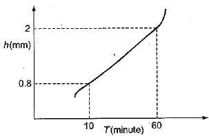
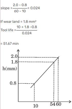
Q. For a critical wear land of 1.8 mm, the cutting tool life (in minute) is
- a)52.00
- b)51.67
- c)51.50
- d)50.00
Correct answer is option 'B'. Can you explain this answer?
During machining, the wear land (h) has been plotted against machining time (T) as given in the following figure.
Q. For a critical wear land of 1.8 mm, the cutting tool life (in minute) is
Q. For a critical wear land of 1.8 mm, the cutting tool life (in minute) is
a)
52.00
b)
51.67
c)
51.50
d)
50.00
|
|
Vibhor Goyal answered |

In grinding operation for faster and bulk material removal- a)fine grain size is used
- b)medium grain size is used
- c)corse grain size is used
- d)any grain size may be used
Correct answer is option 'C'. Can you explain this answer?
In grinding operation for faster and bulk material removal
a)
fine grain size is used
b)
medium grain size is used
c)
corse grain size is used
d)
any grain size may be used
|
|
Rashi Chauhan answered |
When material is removed in bulk, coarse grain is used and this is called roughening operation while in case of finishing and super finishing operation fine grain structure is used at high speed.
Why does crater wear start at some distance from the tool tip?- a)Tool strength is minimum at that region.
- b)Cutting fluid cannot penetrate that region.
- c)Tool temperature is maximum in that region.
- d)Stress on rake face is maximum at that region.
Correct answer is option 'C'. Can you explain this answer?
Why does crater wear start at some distance from the tool tip?
a)
Tool strength is minimum at that region.
b)
Cutting fluid cannot penetrate that region.
c)
Tool temperature is maximum in that region.
d)
Stress on rake face is maximum at that region.
|
|
Shreya Choudhury answered |
Diffusion play an important role in the development of crater wear at a high speed because temperature in the rake face is much higher than that in the flank surface.
Which one of the following gear manufacturing processes is not based on generation principle?- a)Gear hobbing
- b)Gear shaping
- c)Gear milling
- d)Gear shaving
Correct answer is option 'D'. Can you explain this answer?
Which one of the following gear manufacturing processes is not based on generation principle?
a)
Gear hobbing
b)
Gear shaping
c)
Gear milling
d)
Gear shaving
|
|
Anu Deshpande answered |
Gear Manufacturing ProcessesThere are several gear manufacturing processes, including gear hobbing, gear shaping, gear milling, and gear shaving. These processes are used to create gears of different sizes and shapes for various applications.Generation PrincipleThe generation principle is a method used in gear manufacturing that involves using a cutting tool that has the same shape as the gear tooth profile. The cutting tool is moved along the gear blank to create the tooth profile. This method is used in gear hobbing, gear shaping, and gear milling.Gear ShavingGear shaving is a gear manufacturing process that is not based on the generation principle. It involves using a shaving cutter to remove a small amount of material from the gear tooth surface. The shaving cutter is a cylindrical tool with a helical cutting edge. The gear blank is mounted on a special fixture, and the shaving cutter is brought into contact with the gear tooth surface at a specific angle.Advantages of Gear ShavingSome advantages of gear shaving include:1. Improved surface finish: Gear shaving can produce a smoother surface finish than other gear manufacturing processes.2. Increased gear accuracy: Gear shaving can improve the accuracy of gear teeth by removing any surface irregularities.3. Reduced noise: Gear shaving can reduce gear noise by producing a smoother gear tooth surface.ConclusionIn summary, gear manufacturing processes such as gear hobbing, gear shaping, and gear milling are based on the generation principle, while gear shaving is not. Gear shaving is a process that involves using a shaving cutter to improve the surface finish, accuracy, and noise level of gear teeth.
The broaching operation in which the work moves past the stationary tool is called- a)pull broaching
- b)push broaching
- c)surface broaching
- d)continuous broaching
Correct answer is option 'D'. Can you explain this answer?
The broaching operation in which the work moves past the stationary tool is called
a)
pull broaching
b)
push broaching
c)
surface broaching
d)
continuous broaching
|
|
Mansi Rane answered |
The reciprocation of the broach always involves an un-producting return stroke, which is eliminated in a continuous surface broaching machine. In this the small workpieces are mounted on the broaching fixtures which are in turn fixed to a continuously moving conveyor. Broaches which are normally stationary, are kept above the workpieces. The workpieces are pushed past the stationary broaches by means of the conveyor for cutting. The workpieces can be loaded and unloaded onto the conveyor manually or automatically. These machines are used for mass production.
Trepanning operation is performed for- a)finishing a drilled hole
- b)trueing a hole for alignment
- c)producing large hole
- d)sizing a small hole
Correct answer is option 'C'. Can you explain this answer?
Trepanning operation is performed for
a)
finishing a drilled hole
b)
trueing a hole for alignment
c)
producing large hole
d)
sizing a small hole
|
|
Amaan Suhail answered |
Trepanning is a technique used for drilling larger hole diameters where machine power is limited as it is not as power consuming as conventional drilling where the entire hole is converted into chips. The trepanning tool does not machine the whole diameter, only a ring at the periphery
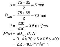
A 150 mm-long, 75 mm-diameter titanium-alloy rod is being reduced in diameter to 65 mm by turning on a lathe in one pass. The spindle rotates at 400 rpm and the tool is traveling at an axial velocity of 200 mm/min. Calculate the MRR.- a)2.2 x 105 mm3/min
- b)4.6 x 105 mm3/min
- c)2.9 x 105 mm3/min
- d)6.1 x 105 mm3/min
Correct answer is option 'A'. Can you explain this answer?
A 150 mm-long, 75 mm-diameter titanium-alloy rod is being reduced in diameter to 65 mm by turning on a lathe in one pass. The spindle rotates at 400 rpm and the tool is traveling at an axial velocity of 200 mm/min. Calculate the MRR.
a)
2.2 x 105 mm3/min
b)
4.6 x 105 mm3/min
c)
2.9 x 105 mm3/min
d)
6.1 x 105 mm3/min
|
|
Kajal Tiwari answered |
Depth of cut,
Tool signature in ASA system comprises of- a)4 elements
- b)5 elements
- c)6 elements
- d)7 elements
Correct answer is option 'D'. Can you explain this answer?
Tool signature in ASA system comprises of
a)
4 elements
b)
5 elements
c)
6 elements
d)
7 elements
|
|
Sanskriti Chakraborty answered |
Tool Signature in ASA System
Tool signature in ASA system comprises of 7 elements. These elements are essential for defining the cutting tool's geometry and parameters accurately.
Elements of Tool Signature in ASA System:
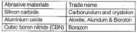
- Back rake angle (α): It is the angle between the rake face and a line perpendicular to the base of the tool.
- Side rake angle (β): It is the angle between the rake face and the side cutting edge of the tool.
- End relief angle (γ): It is the angle between the end of the tool and a line perpendicular to the base of the tool.
- Side relief angle (δ): It is the angle between the side flank and a line perpendicular to the base of the tool.
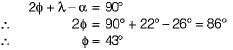
- End cutting edge angle (λ): It is the angle formed between the end cutting edge and a line perpendicular to the base of the tool.
- Side cutting edge angle (φ): It is the angle formed between the side cutting edge and a line perpendicular to the base of the tool.
- End cutting edge inclination angle (υ): It is the angle between the end cutting edge and the reference plane.
Having all these elements in the tool signature allows machinists to accurately set up and use cutting tools for various machining operations in the ASA system.
Tool signature in ASA system comprises of 7 elements. These elements are essential for defining the cutting tool's geometry and parameters accurately.
Elements of Tool Signature in ASA System:
- Back rake angle (α): It is the angle between the rake face and a line perpendicular to the base of the tool.
- Side rake angle (β): It is the angle between the rake face and the side cutting edge of the tool.
- End relief angle (γ): It is the angle between the end of the tool and a line perpendicular to the base of the tool.
- Side relief angle (δ): It is the angle between the side flank and a line perpendicular to the base of the tool.
- End cutting edge angle (λ): It is the angle formed between the end cutting edge and a line perpendicular to the base of the tool.
- Side cutting edge angle (φ): It is the angle formed between the side cutting edge and a line perpendicular to the base of the tool.
- End cutting edge inclination angle (υ): It is the angle between the end cutting edge and the reference plane.
Having all these elements in the tool signature allows machinists to accurately set up and use cutting tools for various machining operations in the ASA system.
Consider the following characteristics:
1. The cutting edge is normal to the cutting velocity.
2. The cutting forces occurs in two direction only.
3. The cutting edge is wider than the depth of cut.
The characteristics applicable to orthogonal cutting would include
- a)1 and 2
- b)1 and 3
- c)2 and 3
- d)1, 2 and 3
Correct answer is option 'A'. Can you explain this answer?
Consider the following characteristics:
1. The cutting edge is normal to the cutting velocity.
2. The cutting forces occurs in two direction only.
3. The cutting edge is wider than the depth of cut.
1. The cutting edge is normal to the cutting velocity.
2. The cutting forces occurs in two direction only.
3. The cutting edge is wider than the depth of cut.
The characteristics applicable to orthogonal cutting would include
a)
1 and 2
b)
1 and 3
c)
2 and 3
d)
1, 2 and 3
|
|
Sagnik Choudhary answered |
In orthogonal cutting, cutting face of the tool is 90° to the line of action or path of the tool.
Shop is confined mainly to such operations as knife turning, broaching and slotting the bulk of machining being done by oblique cutting.
Which of the following sets of tools and processes are normally employed for making large diameter holes?- a)Boring tool
- b)BTA tool and gun drill
- c)Gun drill and boring tool
- d)Boring tool and trepanning
Correct answer is option 'B'. Can you explain this answer?
Which of the following sets of tools and processes are normally employed for making large diameter holes?
a)
Boring tool
b)
BTA tool and gun drill
c)
Gun drill and boring tool
d)
Boring tool and trepanning
|
|
Swati Dasgupta answered |
BTA tool: Boring and trepanning association.
Which of the following indicate better machinability?
1. Smaller shear angle
2. Higher cutting forces
3. Longer tool life
4. Better surface finish- a)1 and 3
- b)2 and 4
- c)1 and 2
- d)3 and 4
Correct answer is option 'D'. Can you explain this answer?
Which of the following indicate better machinability?
1. Smaller shear angle
2. Higher cutting forces
3. Longer tool life
4. Better surface finish
1. Smaller shear angle
2. Higher cutting forces
3. Longer tool life
4. Better surface finish
a)
1 and 3
b)
2 and 4
c)
1 and 2
d)
3 and 4
|
|
Sakshi Basak answered |
Factors which come into play while evaluating the machinability of any metal are:
1. Tool life
2. Form and size of chip and shear angle
3. Cutting forces and power consumption
4. Surface finish
5. Cutting temperature
6. Rate of metal removal per tool grind
7. Rate of cutting under the standard force
8. Uniformity in dimensional accuracy of successive parts
1. Tool life
2. Form and size of chip and shear angle
3. Cutting forces and power consumption
4. Surface finish
5. Cutting temperature
6. Rate of metal removal per tool grind
7. Rate of cutting under the standard force
8. Uniformity in dimensional accuracy of successive parts
For cutting of brass with single-point cutting tool on a lathe, tool should have- a)negative rake angle
- b)positive rake angle
- c)zero rake angle
- d)zero side relief angle
Correct answer is option 'C'. Can you explain this answer?
For cutting of brass with single-point cutting tool on a lathe, tool should have
a)
negative rake angle
b)
positive rake angle
c)
zero rake angle
d)
zero side relief angle
|
|
Sandeep Sengupta answered |
In PERT the activity times follow Beta distribution.
Tool signature in ASA system, the nose radius is indicated in- a)the first position
- b)the middle
- c)the last position
- d)the last but one position
Correct answer is option 'C'. Can you explain this answer?
Tool signature in ASA system, the nose radius is indicated in
a)
the first position
b)
the middle
c)
the last position
d)
the last but one position
|
|
Siddharth Menon answered |
Tool signature in ASA system
BRA-SRA-ERA-SRA-ECEA-SCEA-R
Thus nose radius comes in last position.
BRA-SRA-ERA-SRA-ECEA-SCEA-R
Thus nose radius comes in last position.
The cutting tool that performs orthogonal cutting is
- a)twist drill
- b)broach
- c)helical milling cutter
- d)single point cutting tool for turning
Correct answer is option 'B'. Can you explain this answer?
The cutting tool that performs orthogonal cutting is
a)
twist drill
b)
broach
c)
helical milling cutter
d)
single point cutting tool for turning

|
Constructing Careers answered |
The cutting tool that performs orthogonal cutting is:
2. Single point cutting tool for turning
Orthogonal cutting refers to a cutting process where the cutting edge of the tool is perpendicular to the direction of cutting. This is a characteristic of turning operations using a single point cutting tool, such as in a lathe, where the tool cuts material from a rotating workpiece.
In case of straddle milling the number of side milling cutters mounted on arbor is/are- a)1
- b)2
- c)3
- d)4
Correct answer is option 'B'. Can you explain this answer?
In case of straddle milling the number of side milling cutters mounted on arbor is/are
a)
1
b)
2
c)
3
d)
4
|
|
Manoj Pillai answered |
When milling operation is performed at two different faces simultaneously. By using two milling cutter is called straddle milling.
The function of chip-breaker in a cutting tool is- a)to get long chips
- b)to break the chips into short segments
- c)to remove chips from the bed
- d)none of the above
Correct answer is option 'B'. Can you explain this answer?
The function of chip-breaker in a cutting tool is
a)
to get long chips
b)
to break the chips into short segments
c)
to remove chips from the bed
d)
none of the above
|
|
Suyash Patel answered |
A continuous type of chip is quite troublesome, they should be broken into comparatively small pieces for the ease of handling and to prevent it from becoming a work hazard, hence chip breakers are used to reduce the swarf into small pieces as they are formed.
In metal cutting operation, the approximate ratio of heat distributed among chip, tool and work in that order is- a)80 : 10: 10
- b)33 : 33 : 33
- c)20 : 60 : 10
- d)10:10: 80
Correct answer is option 'A'. Can you explain this answer?
In metal cutting operation, the approximate ratio of heat distributed among chip, tool and work in that order is
a)
80 : 10: 10
b)
33 : 33 : 33
c)
20 : 60 : 10
d)
10:10: 80
|
|
Dhruv Dasgupta answered |
Maximum heat is carried away be chip, i.e., 80% of the total heat generated is carried away by the chip.
In grinding operation for faster and bulk material removal- a)fine grain size is used
- b)medium grain size is used
- c)corse grain size is used
- d)any grain size may be used
Correct answer is option 'C'. Can you explain this answer?
In grinding operation for faster and bulk material removal
a)
fine grain size is used
b)
medium grain size is used
c)
corse grain size is used
d)
any grain size may be used
|
|
Rajat Basu answered |
When material is removed in bulk, coarse grain is used and this is called roughening operation while in case of finishing and super finishing operation fine grain structure is used at high speed.
The broaching operation in which the work moves past the stationary tool is called- a)pull broaching
- b)push broaching
- c)surface broaching
- d)continuous broaching
Correct answer is option 'D'. Can you explain this answer?
The broaching operation in which the work moves past the stationary tool is called
a)
pull broaching
b)
push broaching
c)
surface broaching
d)
continuous broaching
|
|
Anmol Saini answered |
The reciprocation of the broach always involves an un-producting return stroke, which is eliminated in a continuous surface broaching machine. In this the small workpieces are mounted on the broaching fixtures which are in turn fixed to a continuously moving conveyor. Broaches which are normally stationary, are kept above the workpieces. The workpieces are pushed past the stationary broaches by means of the conveyor for cutting. The workpieces can be loaded and unloaded onto the conveyor manually or automatically. These machines are used for mass production.
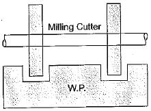
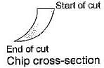
In down milling, the thickness of chip is- a)minimum at the beginning of the cut and maximum at the end of the cut
- b)maximum of the beginning of the cut and minimum at the end of the cut
- c)uniform throughout the cut
- d)none of these
Correct answer is option 'B'. Can you explain this answer?
In down milling, the thickness of chip is
a)
minimum at the beginning of the cut and maximum at the end of the cut
b)
maximum of the beginning of the cut and minimum at the end of the cut
c)
uniform throughout the cut
d)
none of these
|
|
Divya Banerjee answered |
In down milling the maximum thickness of chip is at the start of the cut and decreases to zero at the end of the cut.
What does 36 denote in the following marking of the grinding wheel?5 1 A 36 L 5 V 2 3- a)Structure
- b)Manufacturer’s reference
- c)Nature of abrasive
- d)Abrasive grain size
Correct answer is option 'D'. Can you explain this answer?
What does 36 denote in the following marking of the grinding wheel?
5 1 A 36 L 5 V 2 3
a)
Structure
b)
Manufacturer’s reference
c)
Nature of abrasive
d)
Abrasive grain size
|
|
Preeti Prasad answered |
As 36 is in the second position it shows grain size.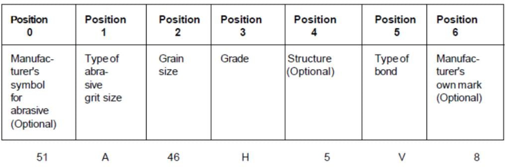
Consider the following actions:
1. Mechanical abrasion
2. Diffusion
3. Plastic deformation
4. Oxidation
Which of the above are the causes of tool wear?- a)2 and 3
- b)l and 2
- c)1, 2 and 4
- d)1 and 3
Correct answer is option 'B'. Can you explain this answer?
Consider the following actions:
1. Mechanical abrasion
2. Diffusion
3. Plastic deformation
4. Oxidation
Which of the above are the causes of tool wear?
1. Mechanical abrasion
2. Diffusion
3. Plastic deformation
4. Oxidation
Which of the above are the causes of tool wear?
a)
2 and 3
b)
l and 2
c)
1, 2 and 4
d)
1 and 3
|
|
Disha Nambiar answered |
Answer should be 1, 2 and 3 but the best answer among available option is (b). Causes of wear are abrasion, sliding, maximum temperature, diffusion and plastic deformation (chipping).
In oblique cutting of metals, the cutting edge of tool is- a)perpendicular to the work pieee
- b)perpendicular to direction of tool travel
- c)parallel to the direction of tool travel
- d)inclined at an angle less than 90° to the direction of tool travel
Correct answer is option 'D'. Can you explain this answer?
In oblique cutting of metals, the cutting edge of tool is
a)
perpendicular to the work pieee
b)
perpendicular to direction of tool travel
c)
parallel to the direction of tool travel
d)
inclined at an angle less than 90° to the direction of tool travel
|
|
Mahi Kaur answered |
Oblique Cutting in Metal Machining
Oblique cutting in metal machining refers to a cutting operation where the cutting edge of the tool is inclined at an angle less than 90 degrees to the direction of tool travel. This type of cutting is commonly used in various machining processes to achieve specific results.
Importance of Oblique Cutting
- Oblique cutting allows for better chip control and improved surface finish compared to orthogonal cutting.
- It helps in reducing cutting forces and power consumption during machining.
- This cutting method is effective in reducing tool wear and extending tool life.
Tool Orientation in Oblique Cutting
In oblique cutting, the cutting edge of the tool is inclined at an angle to the direction of tool travel. This angle is less than 90 degrees, which allows the tool to shear the material at an angle rather than directly against it. This results in reduced cutting forces and improved chip formation.
Benefits of Inclined Cutting Edge
- The inclined cutting edge reduces the contact area between the tool and the workpiece, leading to lower cutting forces.
- It improves chip evacuation by creating a more favorable chip flow direction.
- The shear angle produced by the inclined cutting edge helps in reducing built-up edge formation.
Conclusion
Oblique cutting is a valuable technique in metal machining that offers various advantages over traditional orthogonal cutting. By inclining the cutting edge of the tool at an angle less than 90 degrees to the direction of tool travel, manufacturers can achieve better chip control, surface finish, and overall machining performance.
The angle on which the strength of the tool depends is- a)Rake angle
- b)Cutting angle
- c)Clearance angle
- d)Lip angle
Correct answer is option 'A'. Can you explain this answer?
The angle on which the strength of the tool depends is
a)
Rake angle
b)
Cutting angle
c)
Clearance angle
d)
Lip angle

|
Rounak Choudhary answered |
The Angle on which the Strength of the Tool Depends
The angle on which the strength of the tool depends is the rake angle.
Introduction
In mechanical engineering, the rake angle is an important parameter that affects the performance and strength of cutting tools. It refers to the angle between the rake face of the tool and the direction of cutting motion. The rake angle plays a crucial role in determining the cutting forces, chip formation, and tool life.
Importance of the Rake Angle
The rake angle affects several aspects of cutting tool performance, including:
1. Chip Formation: The rake angle influences the type of chip formed during the cutting process. A positive rake angle (when the rake face is inclined towards the cutting direction) results in continuous chips, while a negative rake angle (when the rake face is inclined away from the cutting direction) produces segmented or discontinuous chips. The type of chip affects cutting forces, heat generation, and chip evacuation.
2. Cutting Forces: The rake angle has a significant impact on the magnitude and direction of cutting forces. A positive rake angle reduces cutting forces by decreasing the friction between the tool and workpiece. On the other hand, a negative rake angle increases cutting forces, which can lead to higher tool wear and power consumption.
3. Tool Life: The rake angle directly affects tool life. A positive rake angle improves tool life by reducing the cutting forces and heat generation. It also promotes better chip control and evacuation. Conversely, a negative rake angle decreases tool life due to increased cutting forces, heat, and tool wear.
Optimization of the Rake Angle
The selection of the rake angle depends on various factors, including the machining operation, workpiece material, cutting speed, and tool material. The goal is to optimize the rake angle to achieve the desired cutting performance, tool life, and surface finish.
1. For soft materials: A positive rake angle is generally preferred as it reduces cutting forces and improves chip control.
2. For hard materials: A negative rake angle may be used to enhance tool strength and withstand higher cutting forces. However, this can increase power consumption and heat generation.
3. For intermittent cutting: A neutral or zero rake angle is often chosen to balance cutting forces, chip control, and tool life.
Conclusion
In summary, the rake angle is a critical factor that influences the strength and performance of cutting tools. It affects chip formation, cutting forces, and tool life. The selection and optimization of the rake angle depend on various factors, including the material being machined and the specific machining operation.
Soft materials can not be economically grinded due to- a)the higher temperature involved
- b)frequent wheel clogging
- c)rapid wheel wear
- d)low work piece stiffness
Correct answer is option 'B'. Can you explain this answer?
Soft materials can not be economically grinded due to
a)
the higher temperature involved
b)
frequent wheel clogging
c)
rapid wheel wear
d)
low work piece stiffness
|
|
Mahi Kaur answered |
Due to production of long continuous chips in case of soft material, continuous chips forced to enter into the space between the abrasive grains and leads to frequent clogging of wheel.
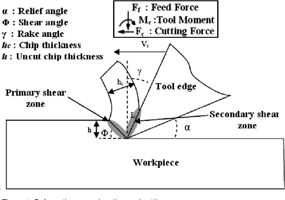
The main source of heat generation in metal cutting is- a)primary shear zone
- b)secondary shear zone
- c)primary shear zone + tool-chip interface
- d)secondary shear zone + tool-chip interface
Correct answer is option 'C'. Can you explain this answer?
The main source of heat generation in metal cutting is
a)
primary shear zone
b)
secondary shear zone
c)
primary shear zone + tool-chip interface
d)
secondary shear zone + tool-chip interface
|
|
Dipika Bose answered |
Explanation:
Metal cutting involves the removal of material from a workpiece using a cutting tool. The main source of heat generation in metal cutting is the primary shear zone + tool-chip interface.
Primary Shear Zone:
- The primary shear zone is the region where the actual cutting of the workpiece material takes place.
- As the cutting tool penetrates the workpiece, it creates high temperatures due to the deformation and shearing of the material.
- Friction between the tool and the workpiece further contributes to heat generation in this zone.
Tool-Chip Interface:
- The tool-chip interface is the contact area between the cutting tool and the chip that is being formed during the cutting process.
- Heat is generated at this interface due to friction between the tool and the chip as well as the deformation of the chip material.
- The high temperatures at the tool-chip interface can lead to tool wear and affect the quality of the machined surface.
Combination of Primary Shear Zone and Tool-Chip Interface:
- The primary shear zone and the tool-chip interface together account for the majority of heat generation in metal cutting.
- Understanding and managing the heat generated in these zones is crucial for optimizing cutting parameters, reducing tool wear, and improving machining efficiency.
In conclusion, the primary shear zone and the tool-chip interface are the main sources of heat generation in metal cutting. By controlling the heat generated in these zones, manufacturers can improve the overall machining process and achieve better results.
Force on individual grain of a grinding wheel is proportional to the- a)work speed
- b)square of work speed
- c)cube of work speed
- d)fourth power of work speed
Correct answer is option 'B'. Can you explain this answer?
Force on individual grain of a grinding wheel is proportional to the
a)
work speed
b)
square of work speed
c)
cube of work speed
d)
fourth power of work speed
|
|
Devika Tiwari answered |
Force on individual grain of a grinding wheel is proportional to the square of work speed.
Grinding is a machining process that involves the removal of material from a workpiece using a grinding wheel. The grinding wheel is made up of abrasive grains that are bonded together and rotate at high speeds to perform the cutting action.
Force on individual grain:
When the grinding wheel comes into contact with the workpiece, each individual abrasive grain on the surface of the wheel interacts with the workpiece material. This interaction creates a force on the grain, which is responsible for the material removal.
Factors affecting the force:
The force on an individual grain of the grinding wheel depends on several factors, including the work speed. The work speed refers to the relative speed between the grinding wheel and the workpiece surface.
Explanation:
The force on an individual grain can be understood by considering the cutting action of the grain on the workpiece material. As the grain moves across the workpiece surface, it cuts and removes material. This cutting action requires the application of a cutting force.
The cutting force is influenced by the speed at which the grain moves across the workpiece surface. At higher work speeds, the grain has less time to engage with the workpiece material, resulting in a shorter contact time. This shorter contact time leads to a higher cutting force being applied by the grain.
Mathematically, the force on an individual grain can be expressed as:
F = K * V^n
Where:
F = Force on grain
K = Constant
V = Work speed
n = Exponent
Proportional to the square of work speed:
The relationship between the force on the grain and the work speed can be determined experimentally. It has been observed that the force on the grain is proportional to the square of the work speed (V^2).
This relationship can be explained by considering the cutting action of the grain. The cutting force is directly related to the rate at which material is being removed. At higher work speeds, the rate of material removal increases, leading to a higher cutting force. The square relationship between the force and the work speed can be attributed to the fact that the cutting force is proportional to the product of the work speed and the rate of material removal.
Therefore, the correct answer is option 'B', the force on an individual grain of a grinding wheel is proportional to the square of the work speed.
Chapter doubts & questions for Machining & Machine Tool Operations - Manufacturing Engineering 2025 is part of Mechanical Engineering exam preparation. The chapters have been prepared according to the Mechanical Engineering exam syllabus. The Chapter doubts & questions, notes, tests & MCQs are made for Mechanical Engineering 2025 Exam. Find important definitions, questions, notes, meanings, examples, exercises, MCQs and online tests here.
Chapter doubts & questions of Machining & Machine Tool Operations - Manufacturing Engineering in English & Hindi are available as part of Mechanical Engineering exam.
Download more important topics, notes, lectures and mock test series for Mechanical Engineering Exam by signing up for free.
Manufacturing Engineering
56 videos|80 docs|29 tests
|
|
© EduRev
|
Education Revolution
|


|


Signup to see your scores
go up within 7 days!
Access 1000+ FREE Docs, Videos and Tests
Takes less than 10 seconds to signup